PayPal now available at checkout
Free US Shipping On Orders $99+
Previous slide
Next slide
June 2022 orig., June 2024 rev.
Please dispose of all waste products and materials through proper channels to avoid contamination of the environment.
Any damage or issues resulting from improper service will not be covered by warranty. If you have a shock still in its original warranty period and do not wish to void your warranty, please contact an authorized Cane Creek service center.
These service instructions cover the basic service procedures using standard service kits. If your suspension requires parts beyond standard replacement parts – shaft, damper tubes, end eyes – please consult your authorized Cane Creek service center or contact us at our Cane Creek Support Center.
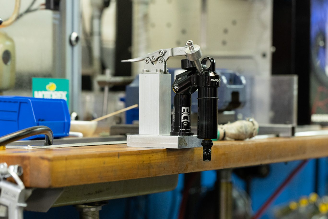
The DBair CS and Coil CS share many service steps. Additionally, the Standard and Trunnion variants of both models have identical service procedures other than where to clamp the cylinder head. Some images in these instructions may not be identical to the the valve body or outer damper tube on the Air CS, but process is the same for the shock in the image and the shock on your bench.
Additionally, running changes happened throughout the lifespan of the Air CS. Many of those are addressed in the Technical Service Bulletins below, but always take note of the way the shock is originally built and replicate that during reassembly to maintain the original performance, tune, set up, etc.
BAD0241 – DBair/DBair CS Air Spring Rebuild Kit
BAD2375 – DBair CS Damper Rebuild Kit
DBT018 – DB Seal Head Pin Spanner Wrench
AAD1361-01 – DBCoil/ DBAir – Oil Fill Needle Adapter
DBT016 – DB Gas Fill Needle
AAD0555 – 8mm & 9.5mm Shaft Clamp
AAD0756 – DB Valve Seat Tool
AAD1002 – DBair Air Seal Head Bullet
BCD0344 – Kitsuma/DBair/DBair IL Air Seal Head Tool
DBT012 – DB IFP Setting Tool
Allen wrenches – 1.5 & 3mm
Torx wrenches – T20
Sockets – 6mm
Crowfoot wrenches – 1/2″
Torque wrenches
Pick
Pin Spanner
Needle Nose Pliers
Strap wrench
Suspension Grease
PolyLube Grease
Motorex 4wt Racing Fork Oil
Royal Purple 10w-30
Vacuum Oil Fill Machine
Nitrogen Fill System
Torque & Loctite Chart
| Part | Torque Spec | Loctite Spec |
| Shaft Bolt | 5 Nm | 243 (Blue) |
| Climb Switch Plate Cover | 0.16 Nm | 243 (Blue) |
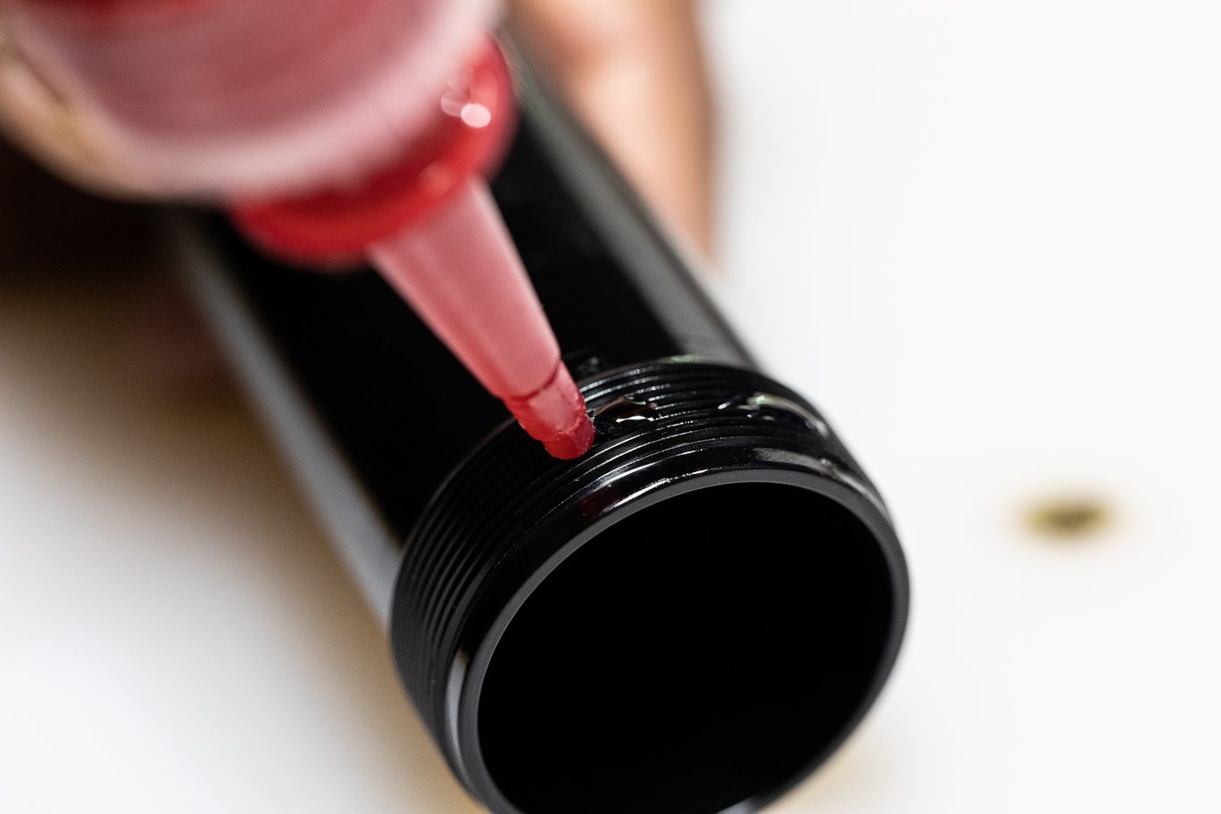
| Outer Damper Tube | Tight | 263 (Red) |
| Valve Seat | 4.8 Nm | None |
| Climb Switch Screw | 1.2 Nm | 243 (Blue) |
| Oil Seal Head | 15 Nm | None |
| Air Piston Screws | 4 Nm | 243 (Blue) |
| End Eye | 4.8 Nm | 243 (Blue) |
| Inner Air Can/Air Seal Head | 22.6 Nm | None (PolyLube) |
Oil Chart
| Oil Location | Oil Type | Oil Amount |
| Air Can | Royal Purple 10w-30 | 8 mL |
| Damper Fill | Motorex 4wt Racing Fork Oil | Fill to 3 Bars |
Nitrogen Chart
| Nitrogen Location | Nitrogen Pressure |
| Valve Body | 11-12 Bars |
Review all related TSBs before performing any service.
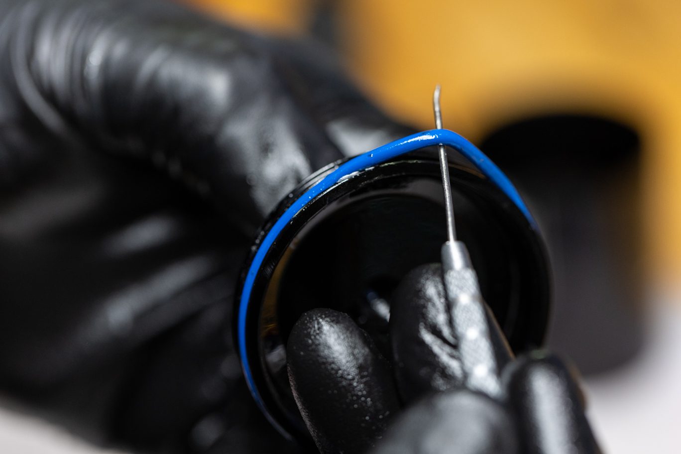
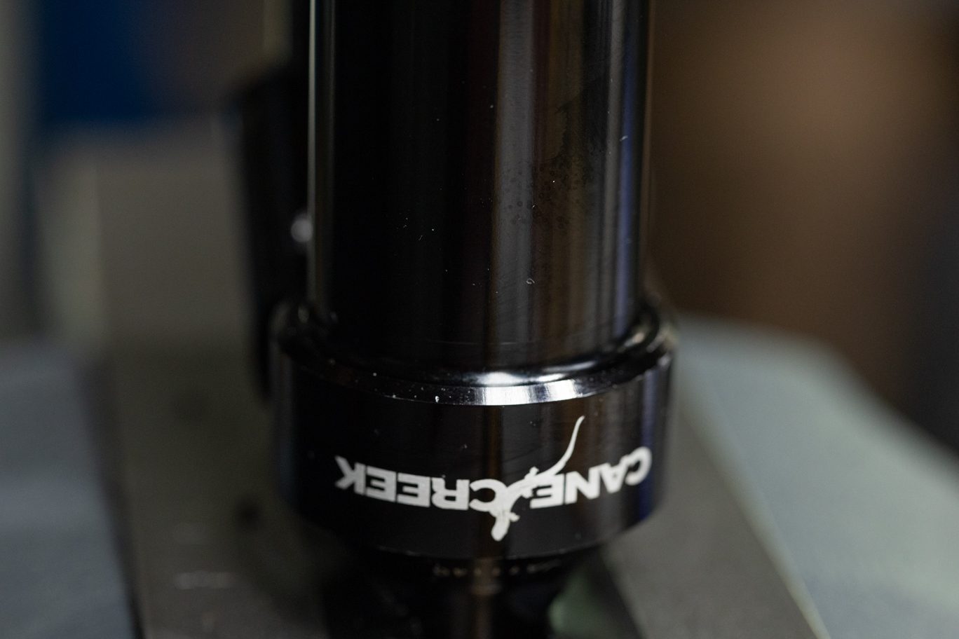
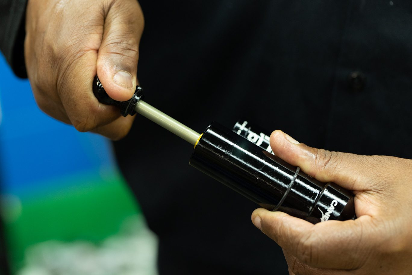
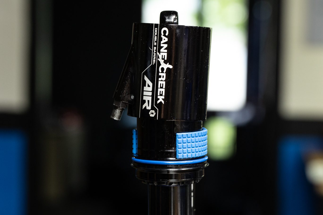
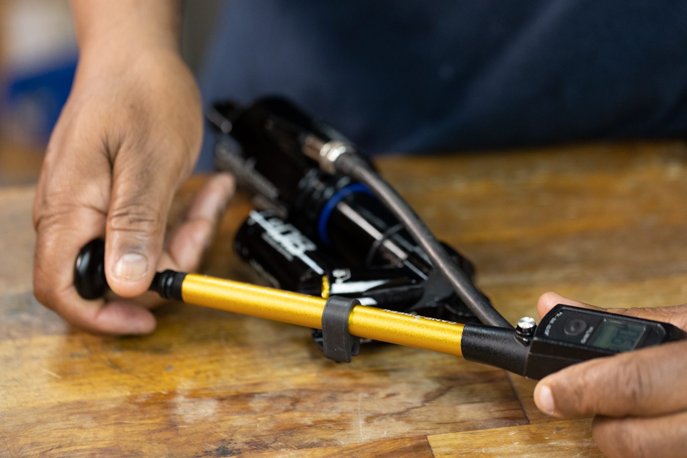
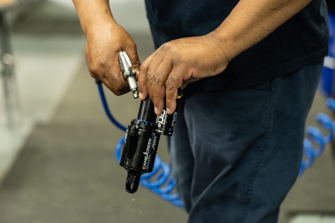
Clean shock. Record tune if desired. Remove hardware. Remove bushings if replacing. Remove valve cap. Bleed air from shock using shock pump. Be sure to depressurize shock slowly to avoid trapping air in the negative chamber.
TSB018 – DBair CS & DBcoil CS Eyelet Change
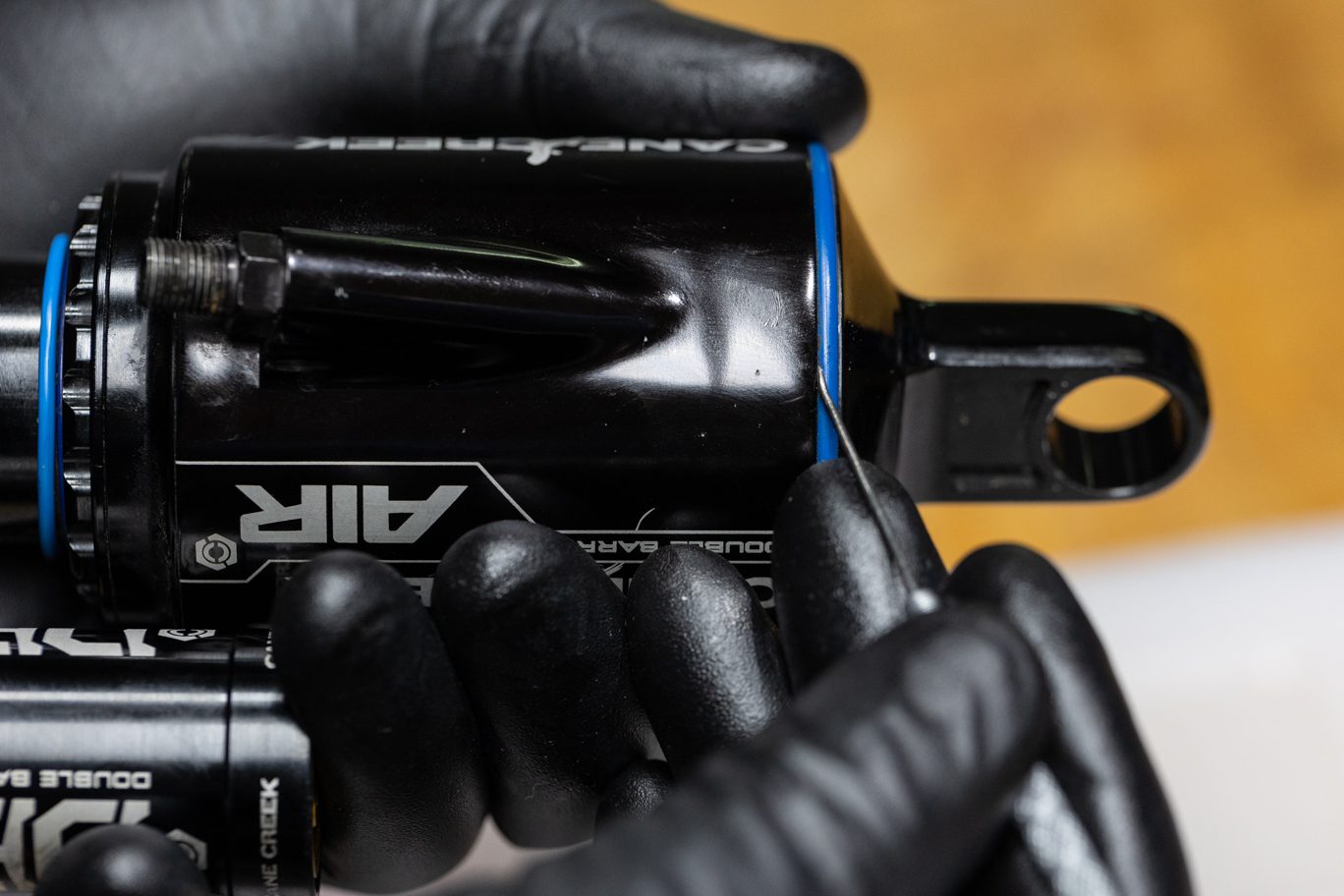
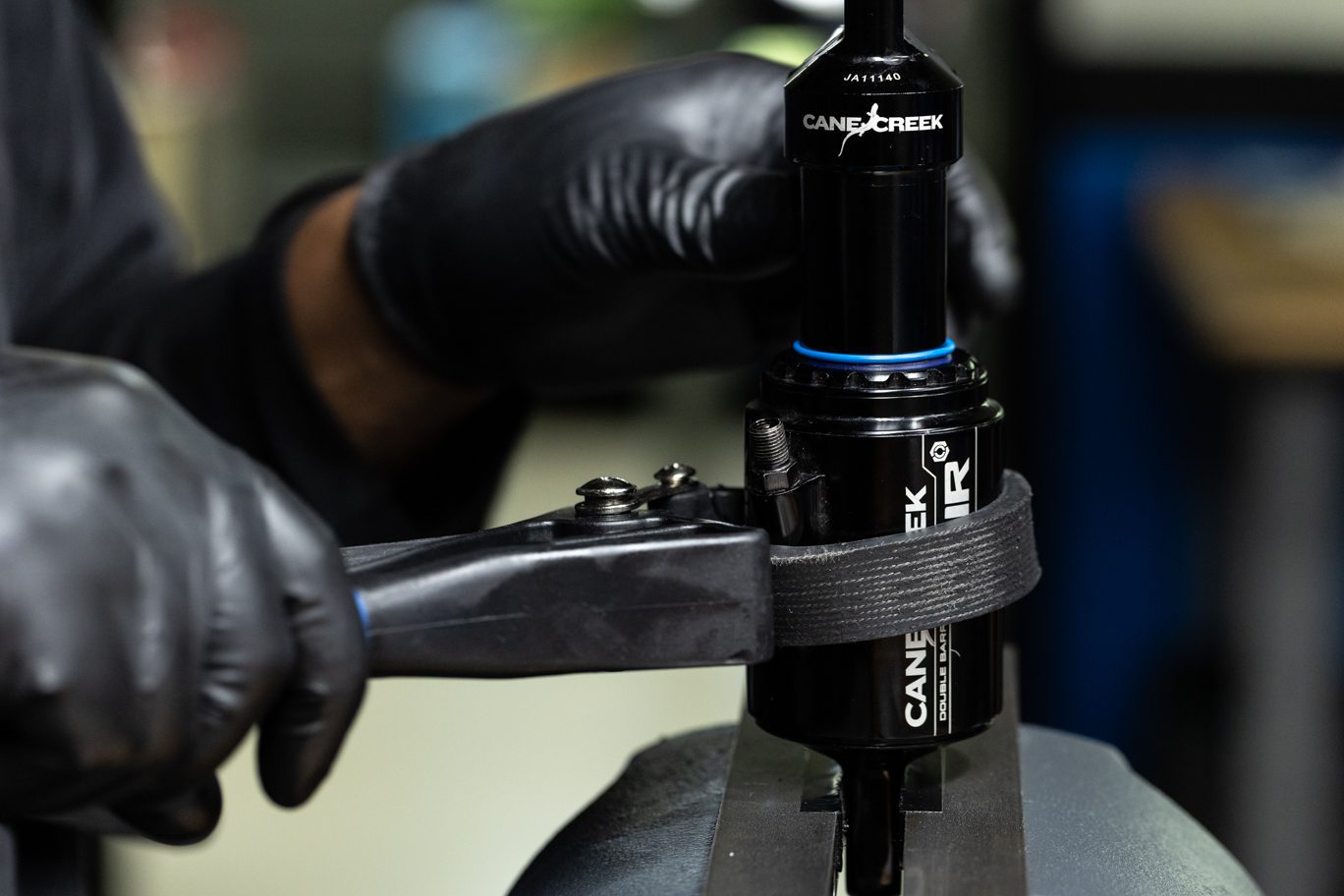
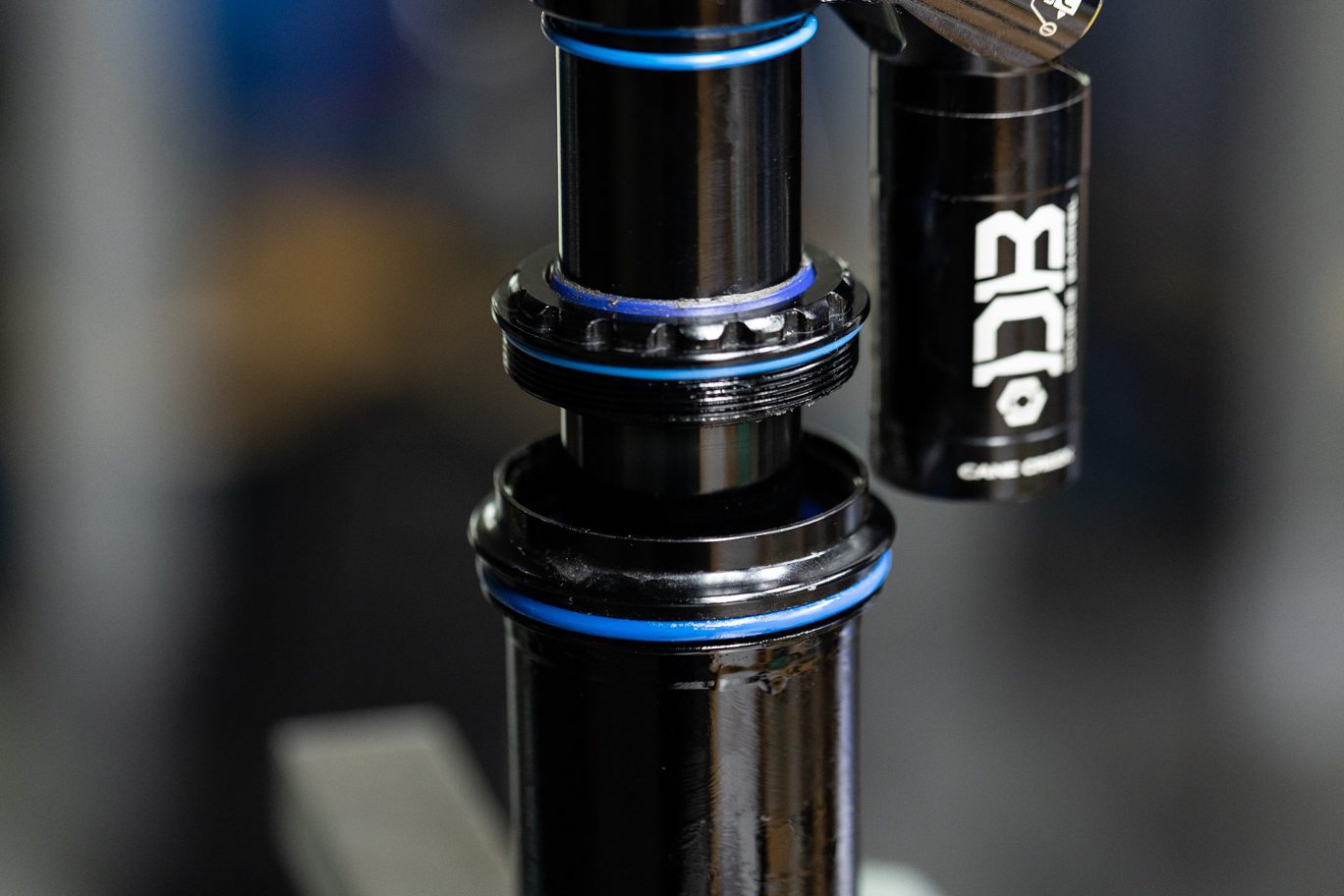
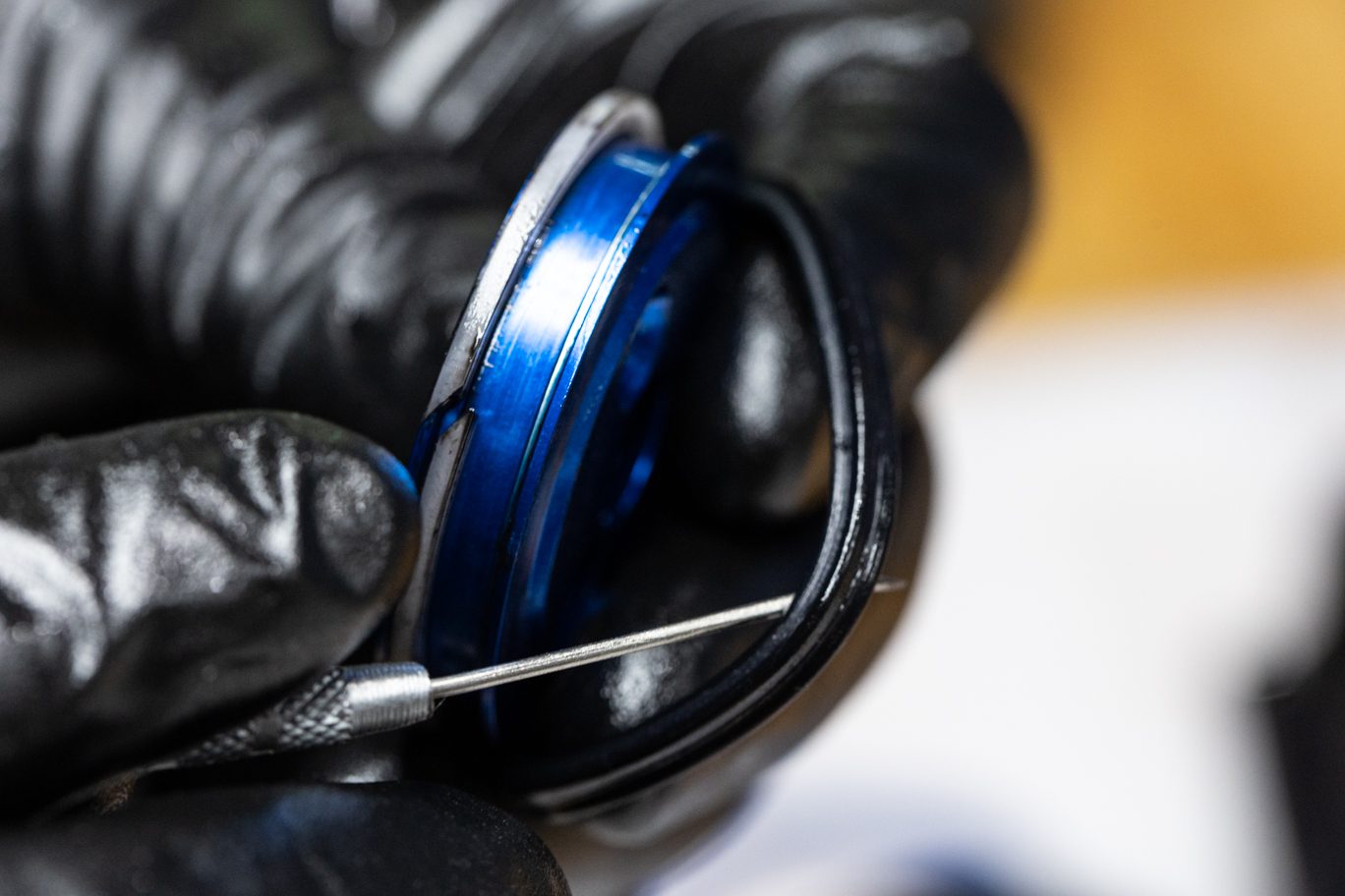
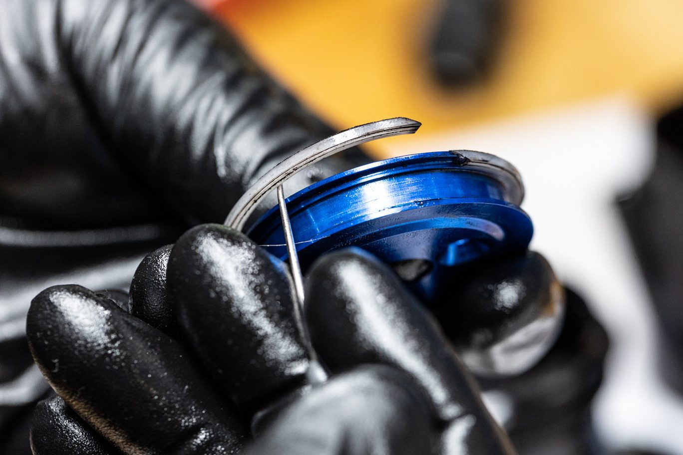
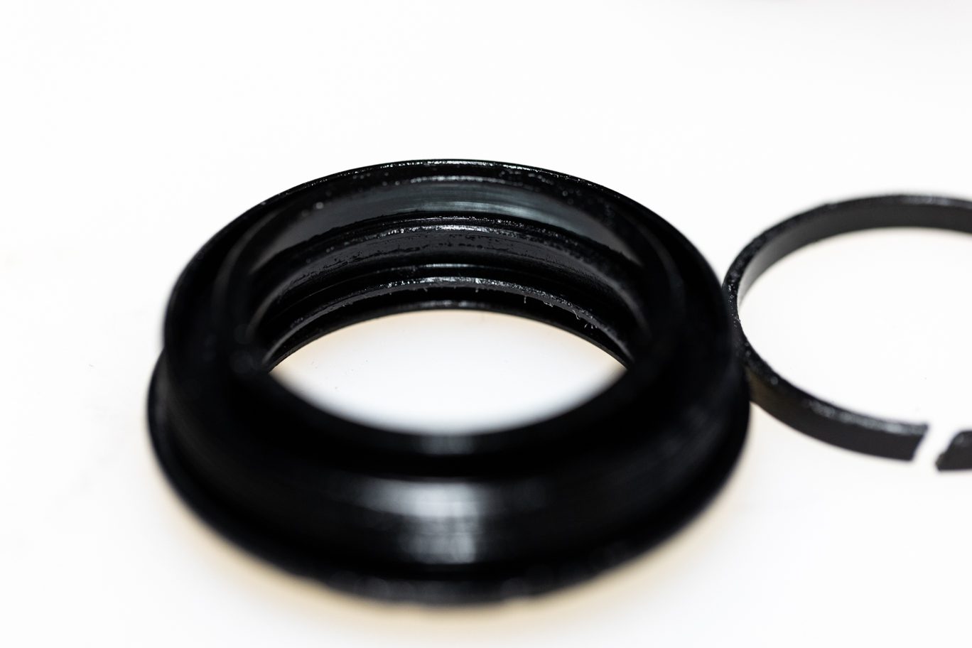
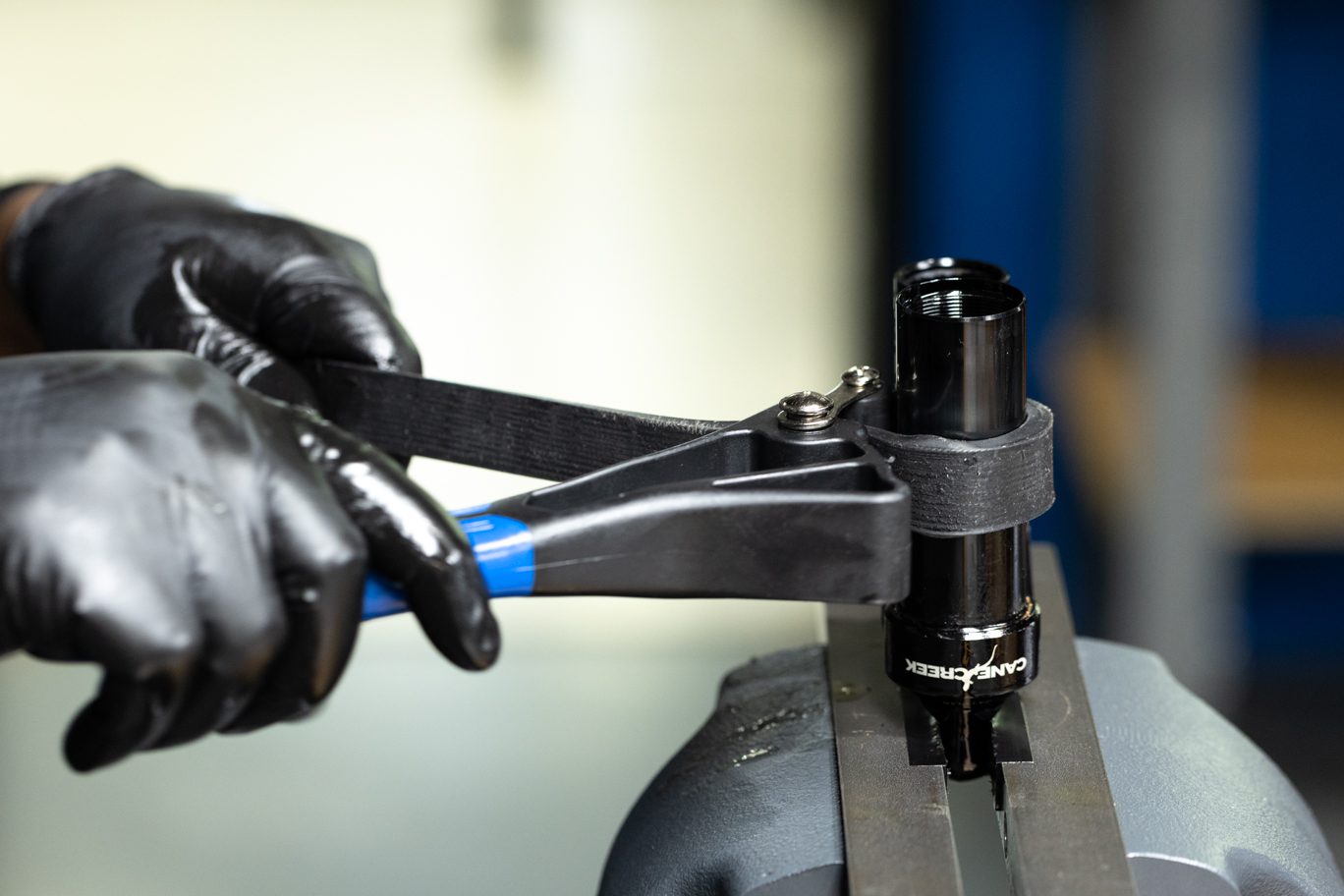
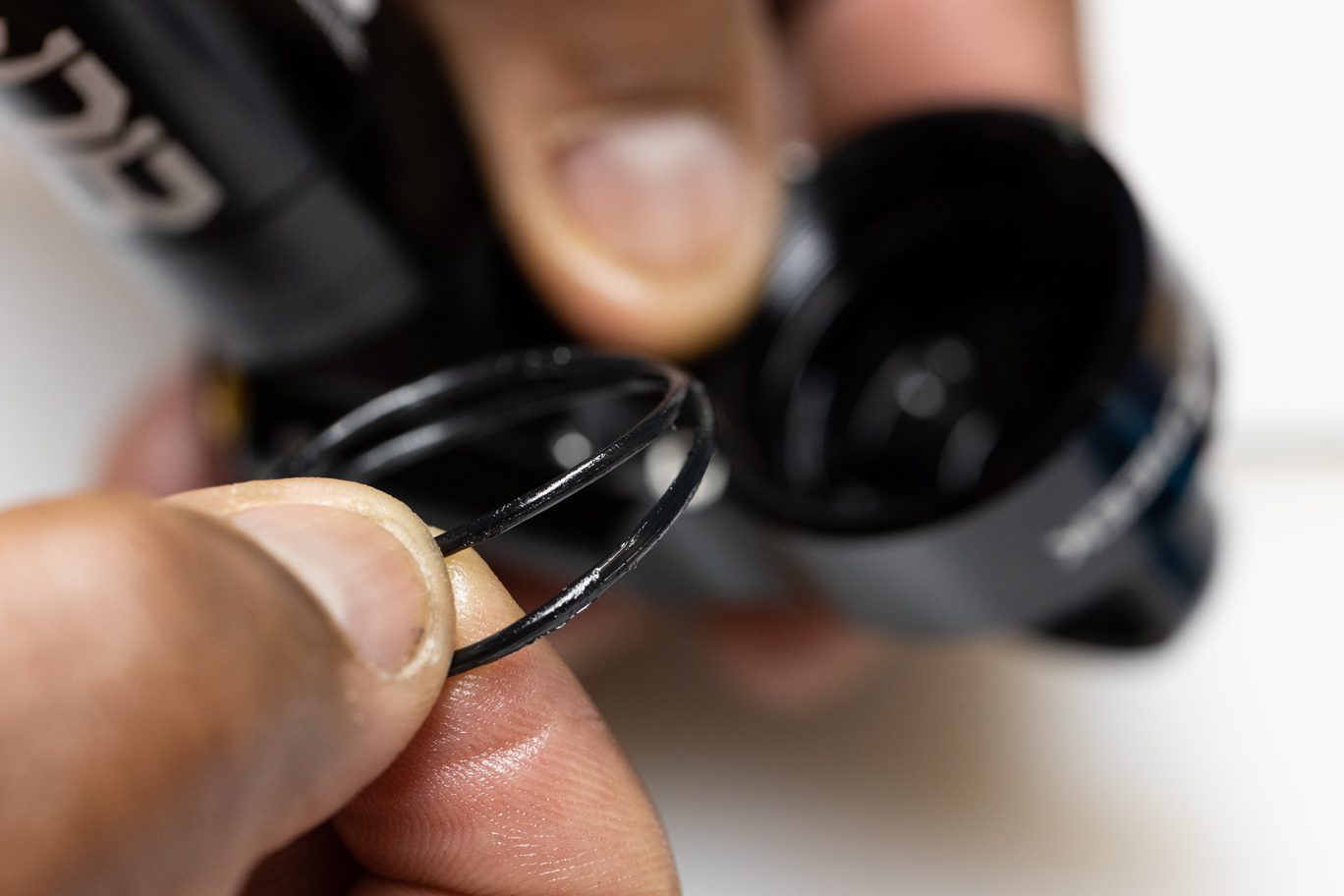
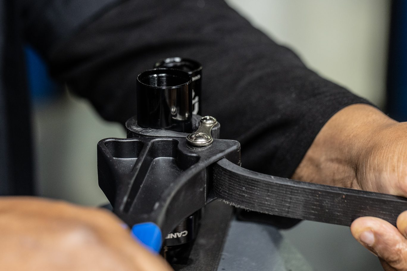
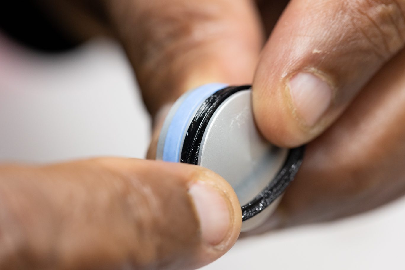
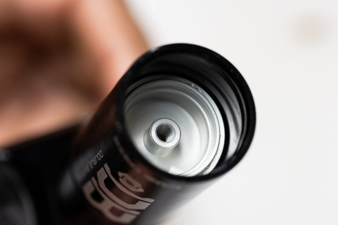
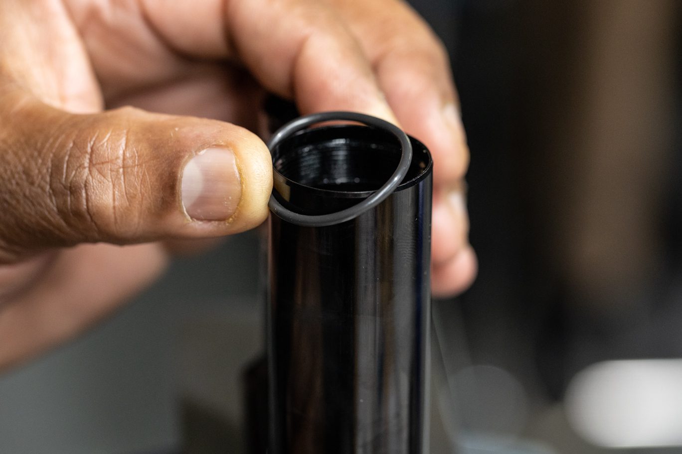
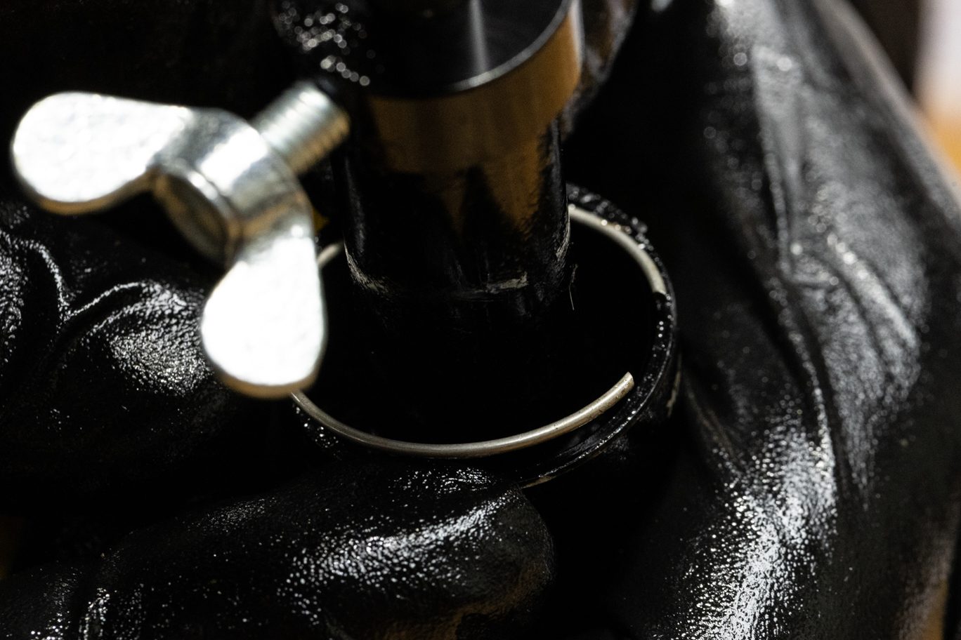
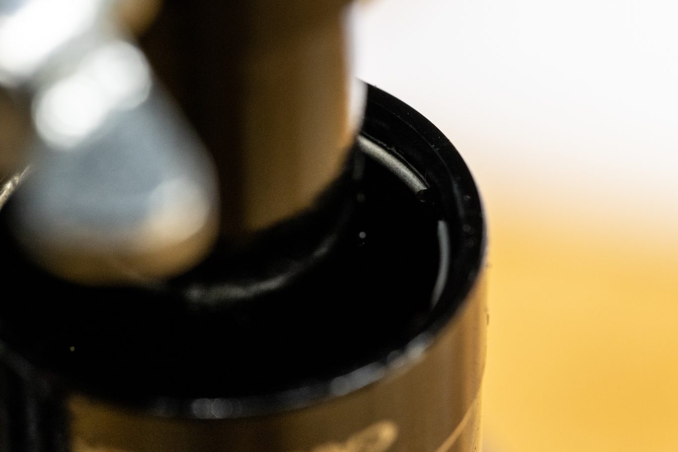
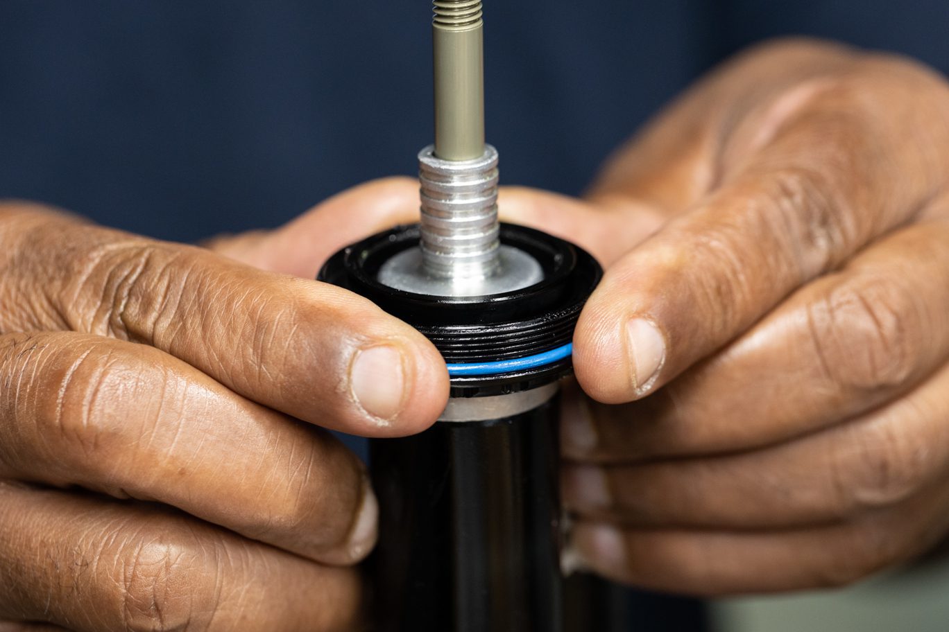
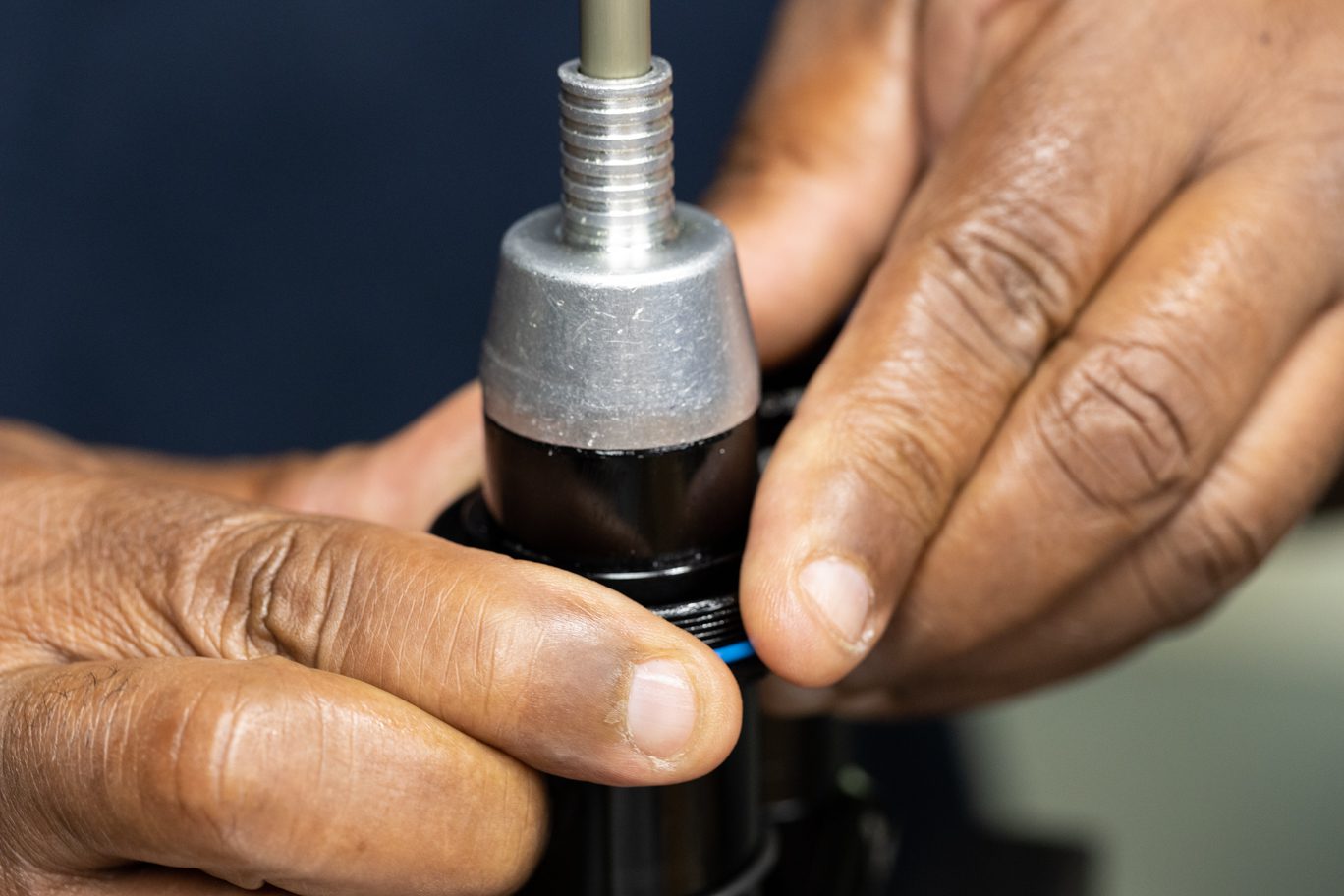
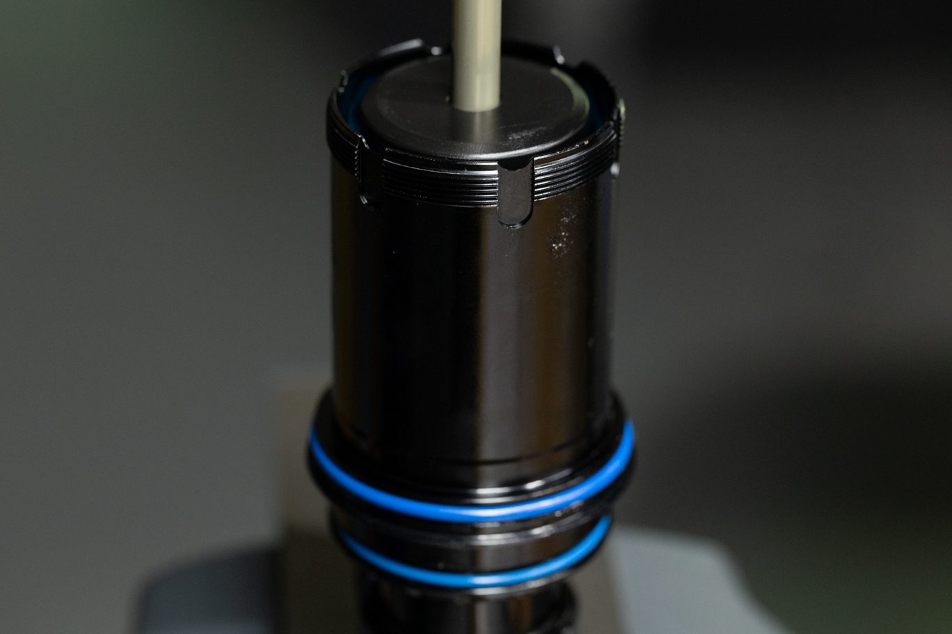
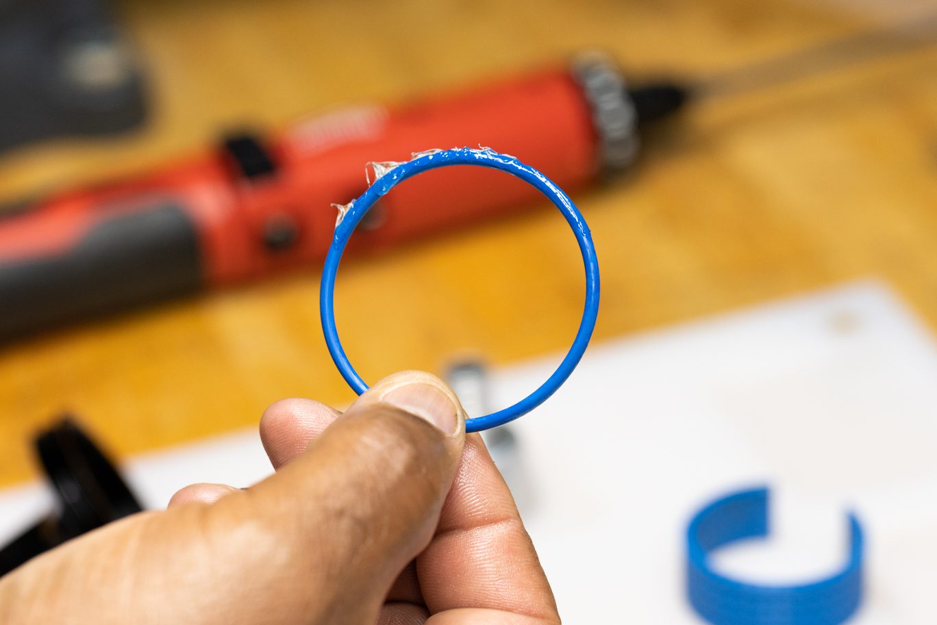
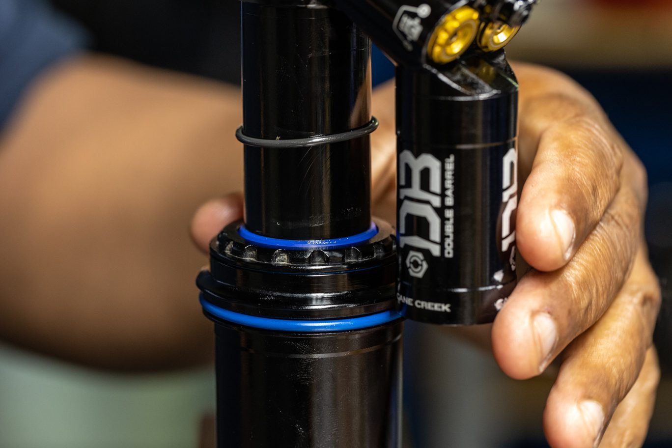
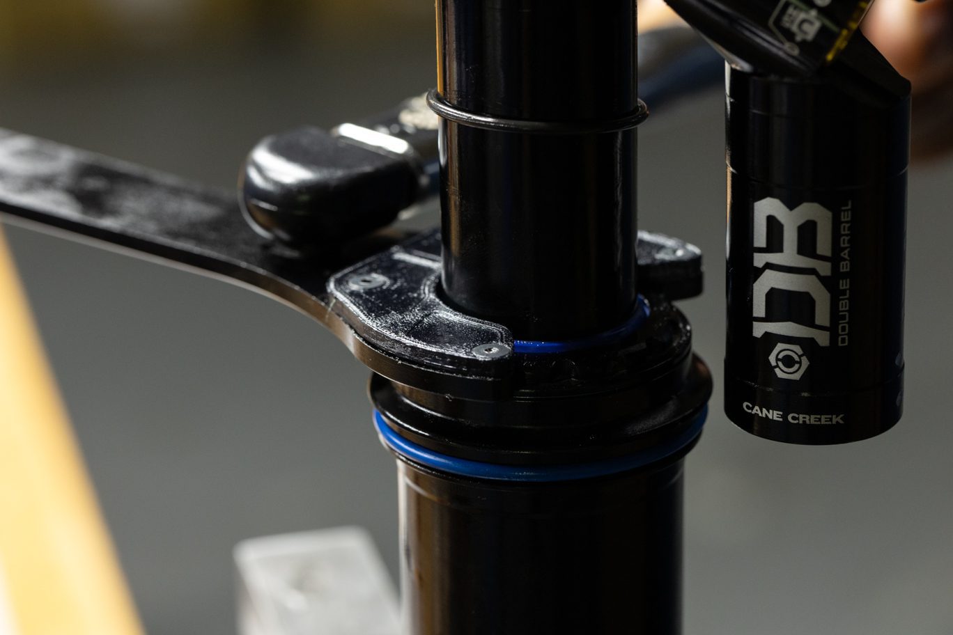
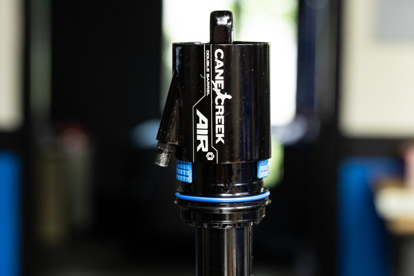
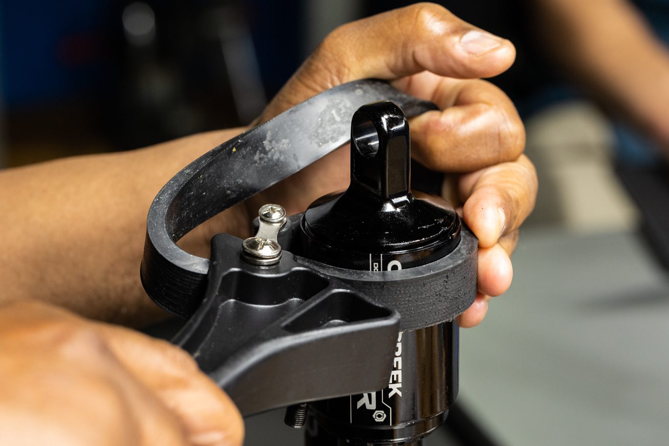
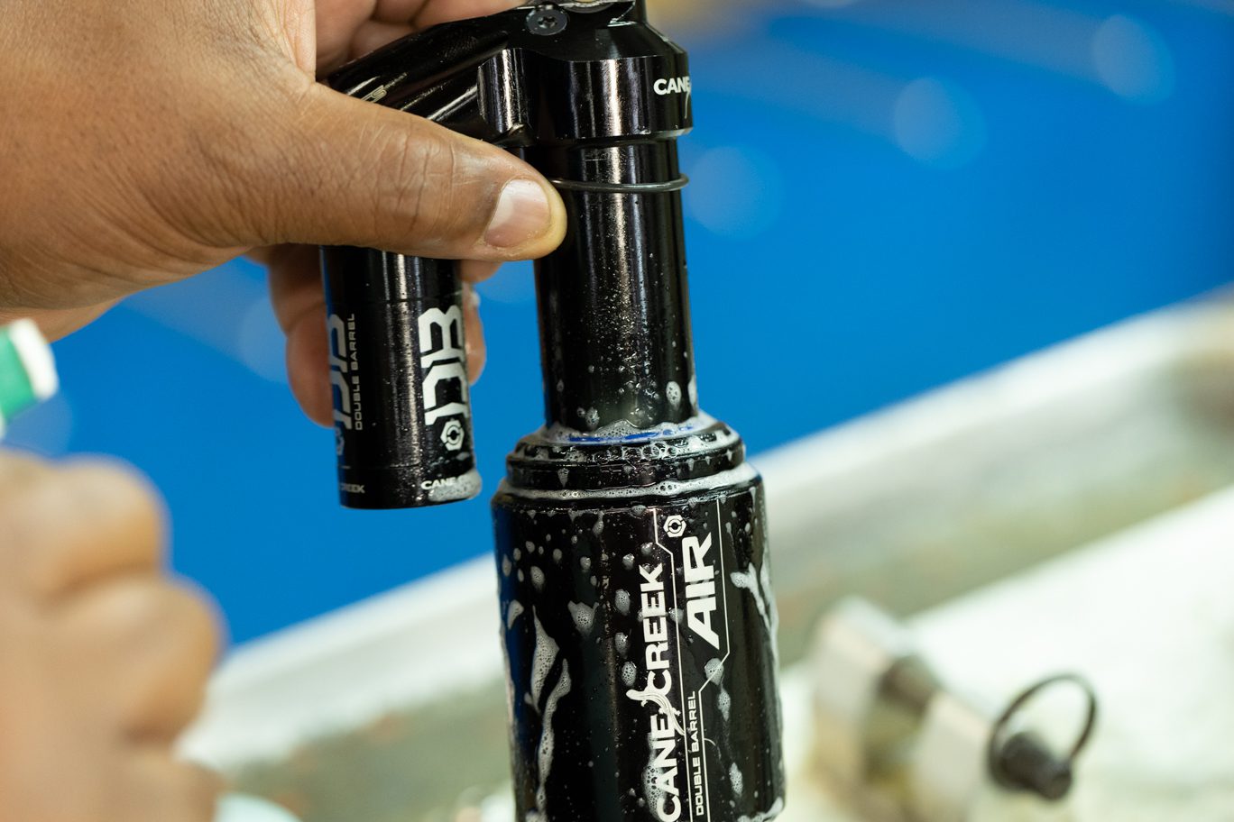
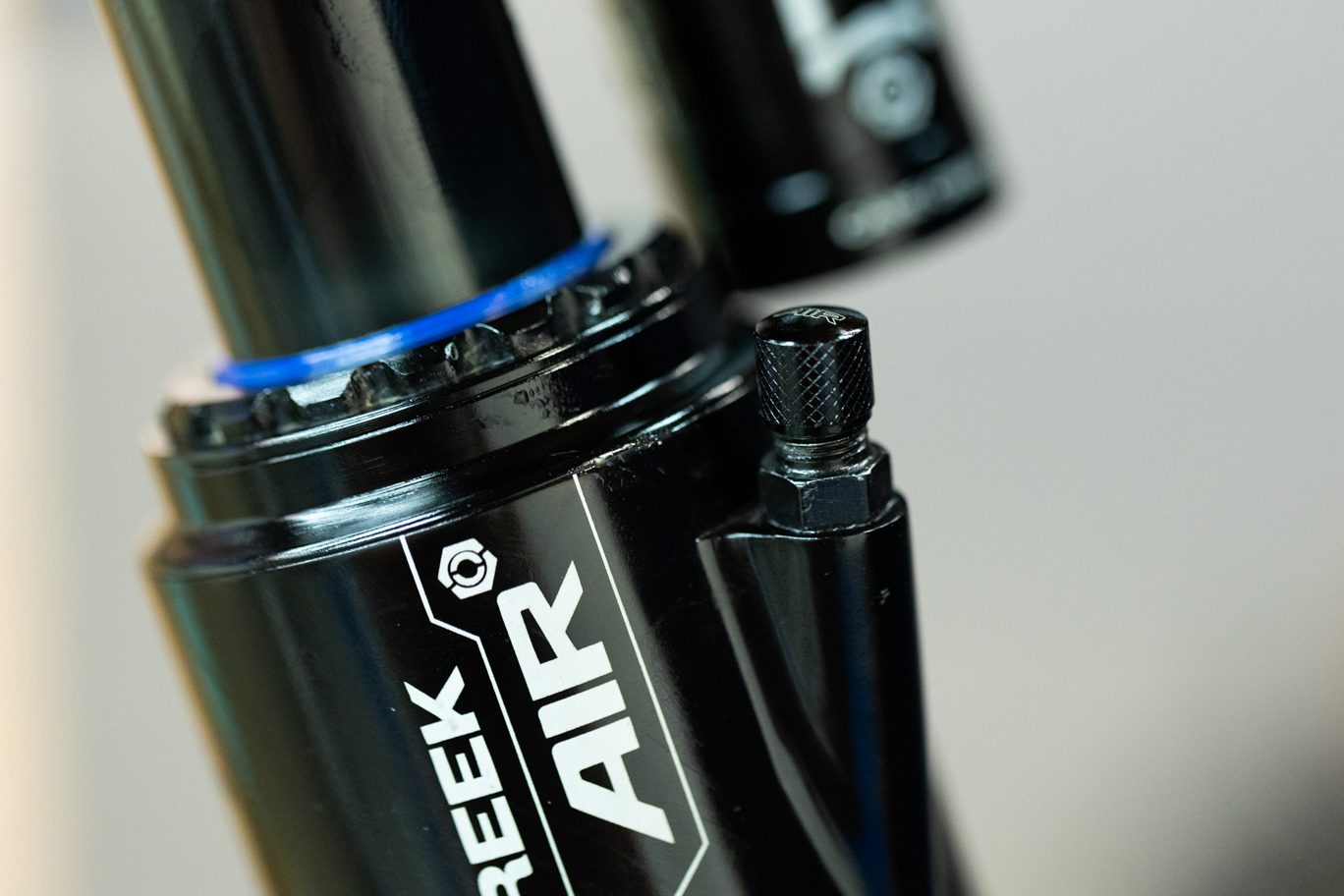
Remove air can retaining o-ring. Clamp shock in soft jaw vise. Using strap wrench, turn air can and pull down away from air seal head. Unclamp shock. Remove air can. Note and remove any air volume reduction.
Always use extreme caution when using a pick in this step or others to avoid scratching metal parts. Failure to do this can create scratches in the o-ring glands which cause leak paths for oil or gas. When possible, pinch and remove o-rings rather than using a pick.
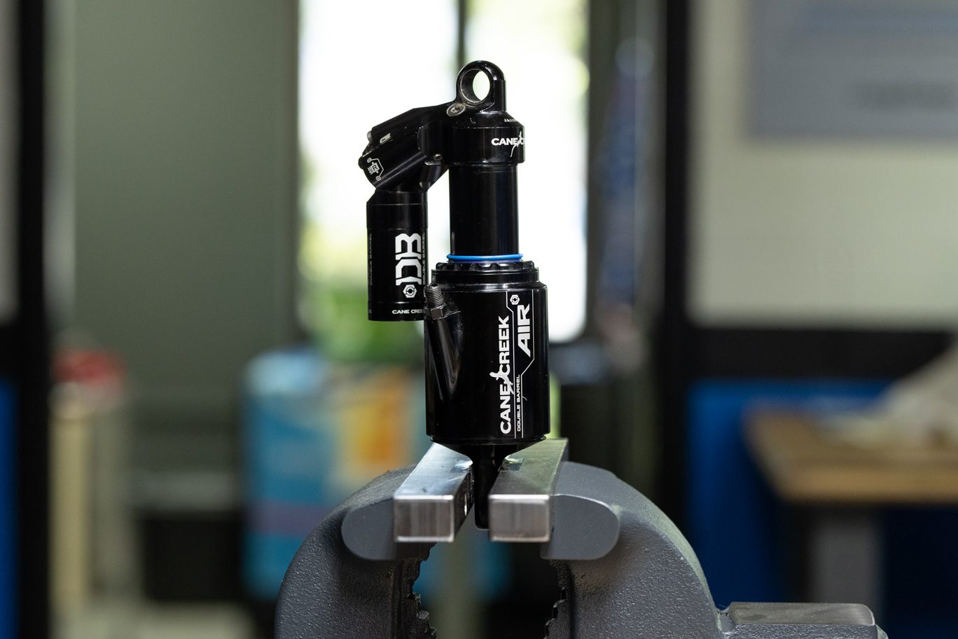
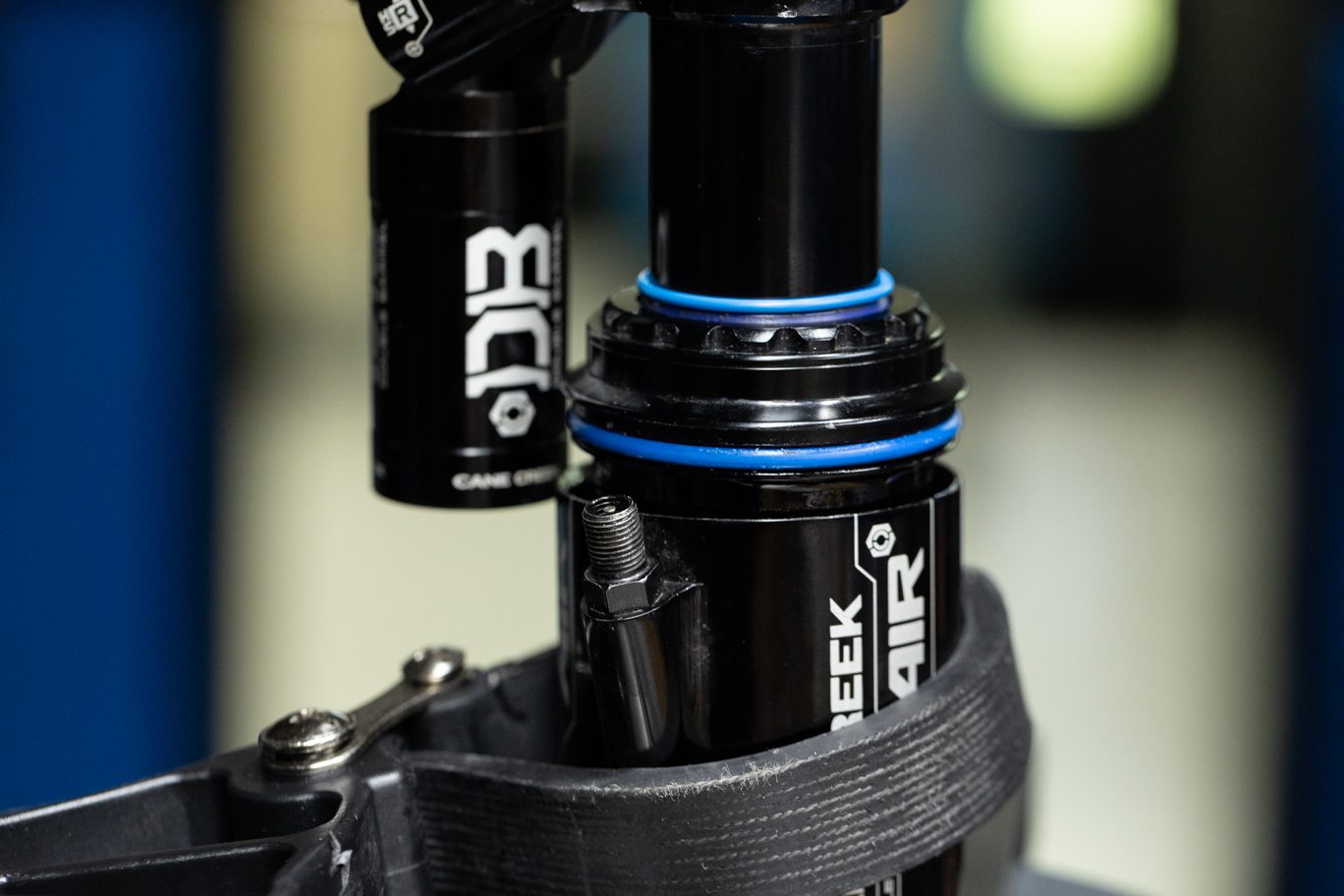
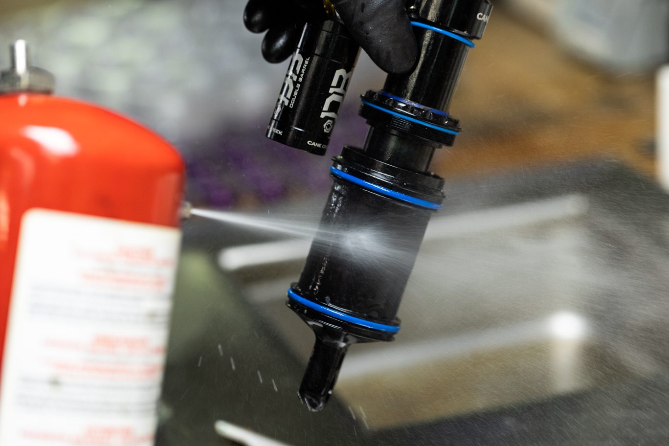
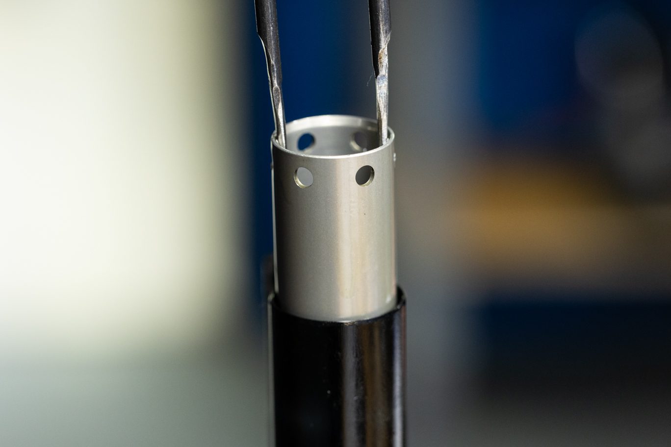
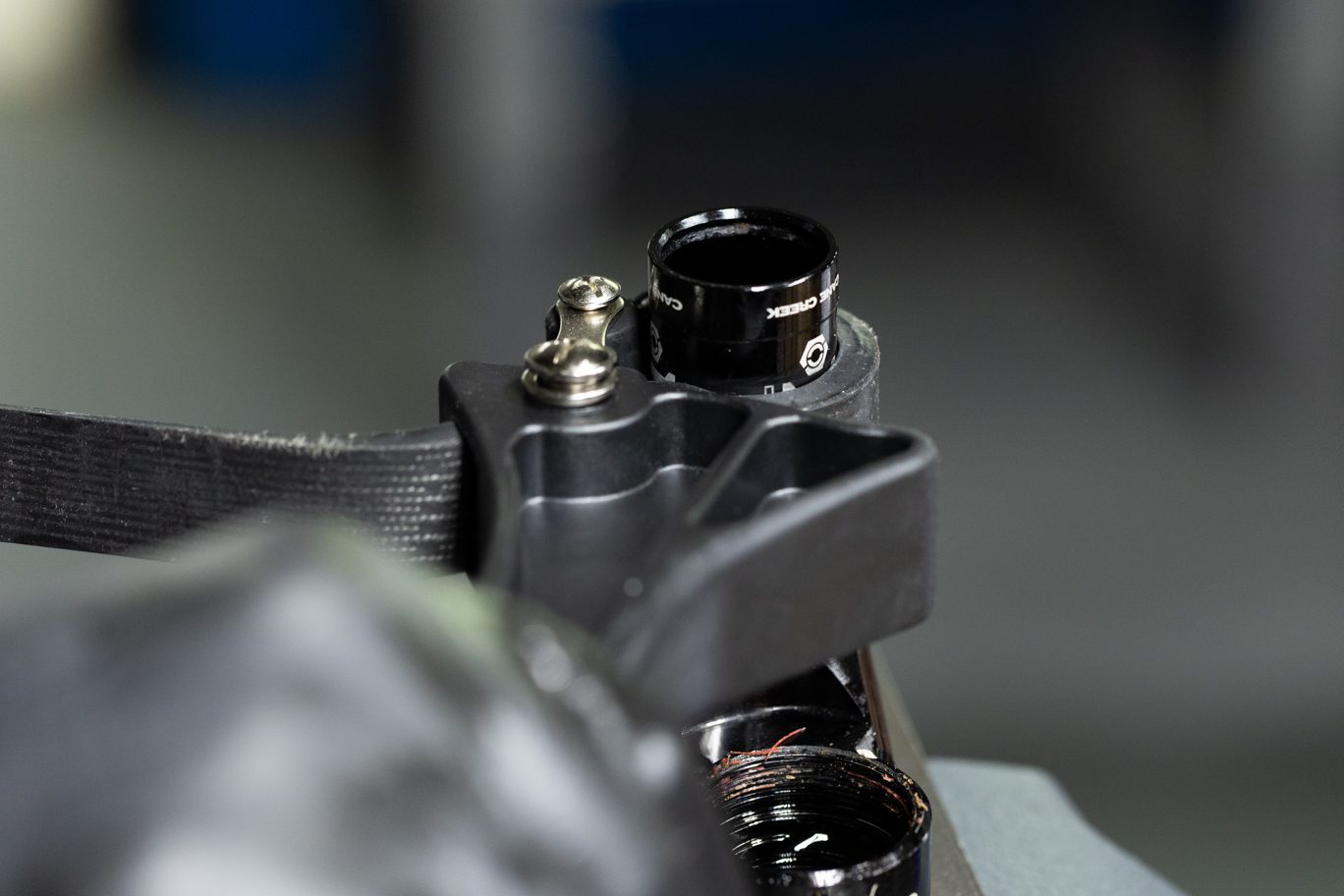
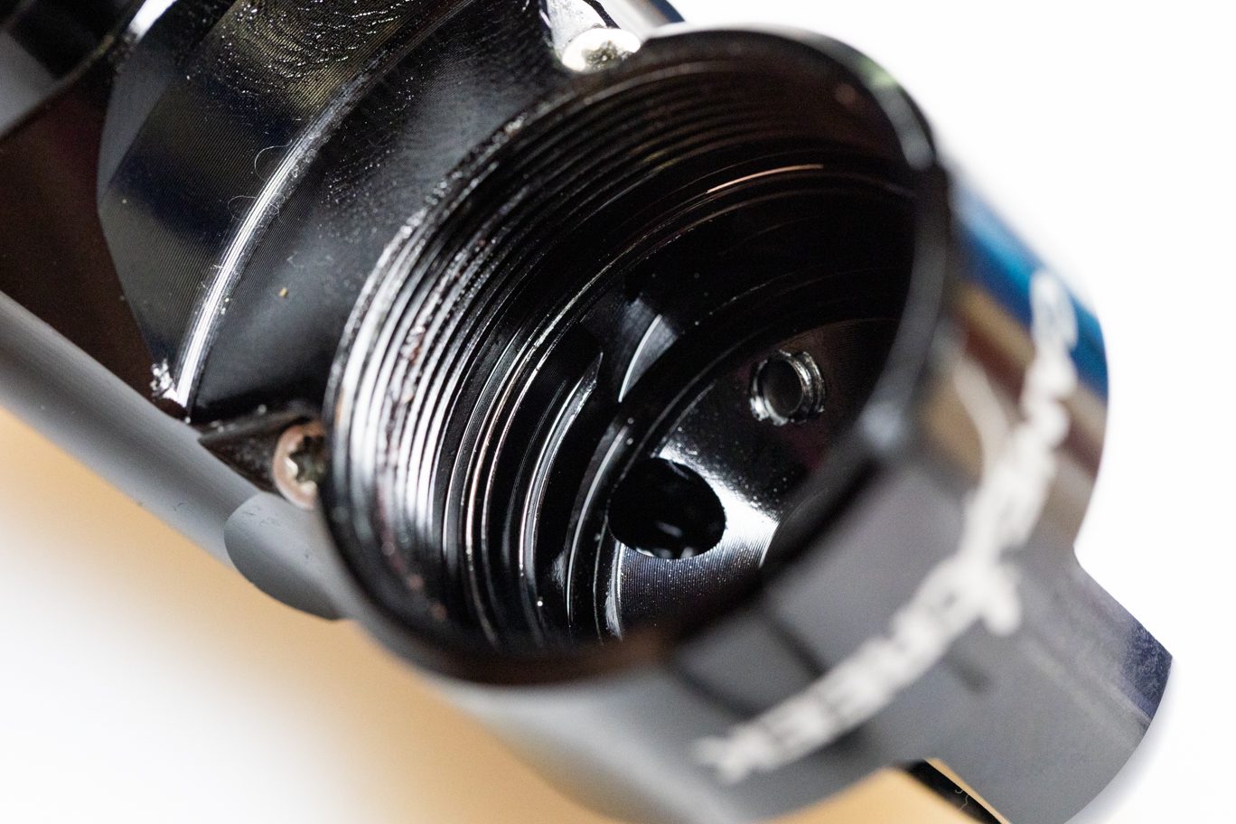
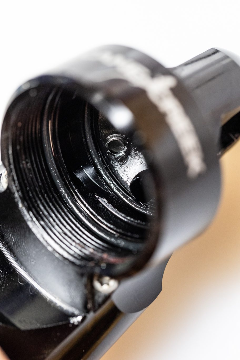
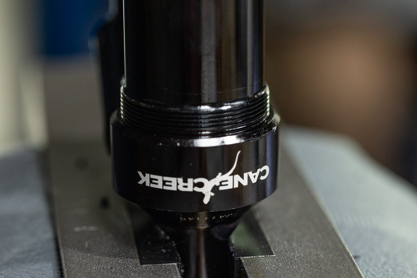
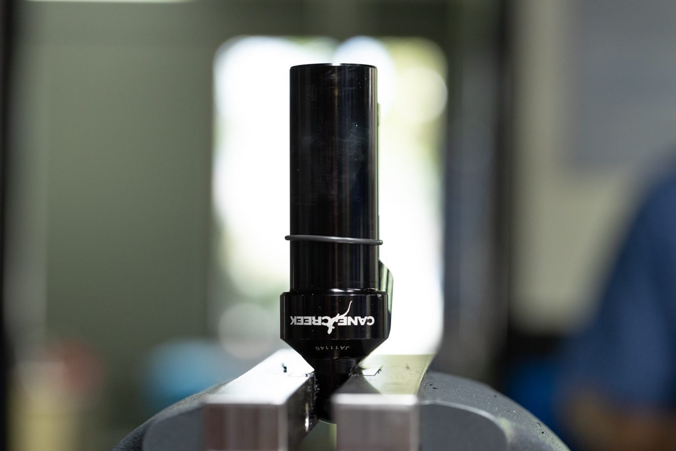
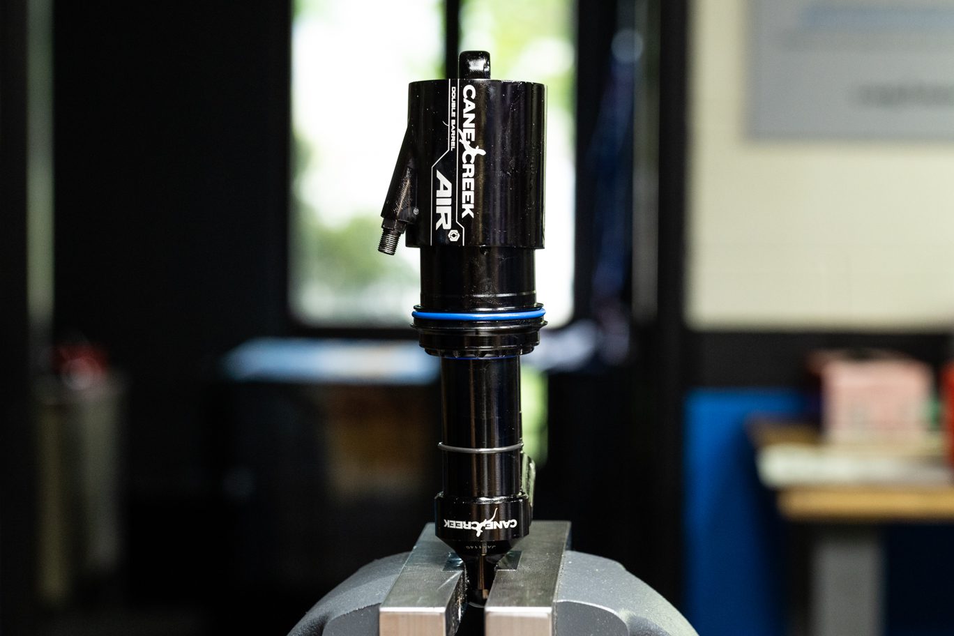
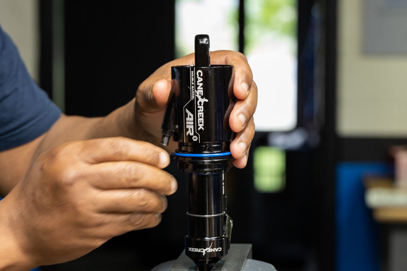
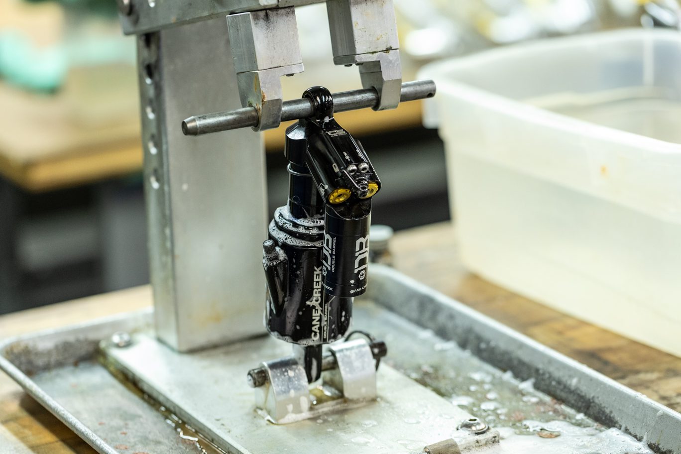
Reclamp shock. Align teeth on Air Seal Head Tool (BCD0344) with grooves on air seal head. Unthread air seal head from inner air can. Use strap wrench on inner air can to prevent rotation in end eye if necessary. Thoroughly clean inner air can with alcohol or other cleaner. Using strap wrech, remove inner air can from end eye.
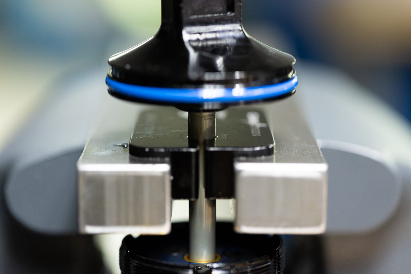
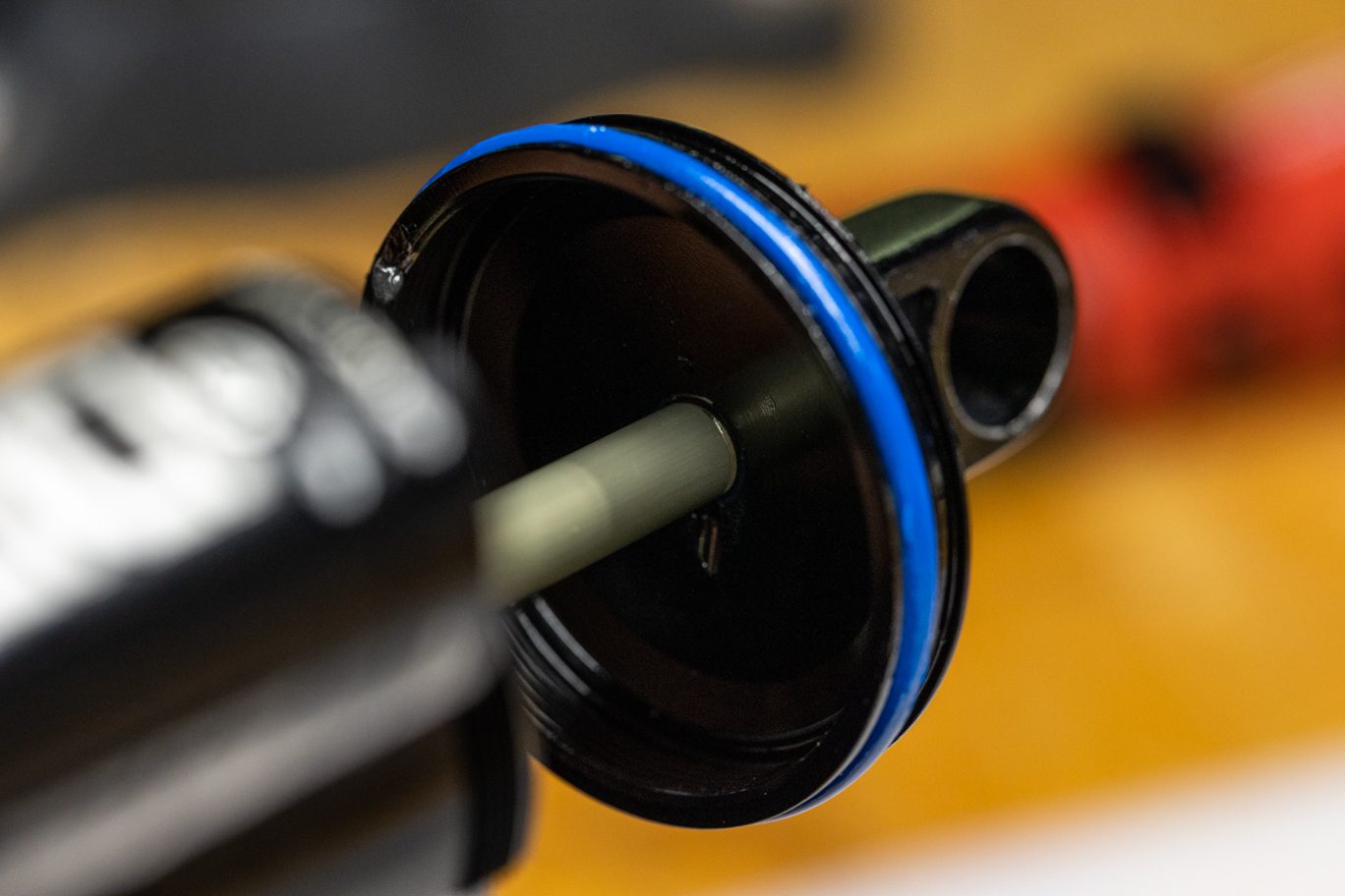
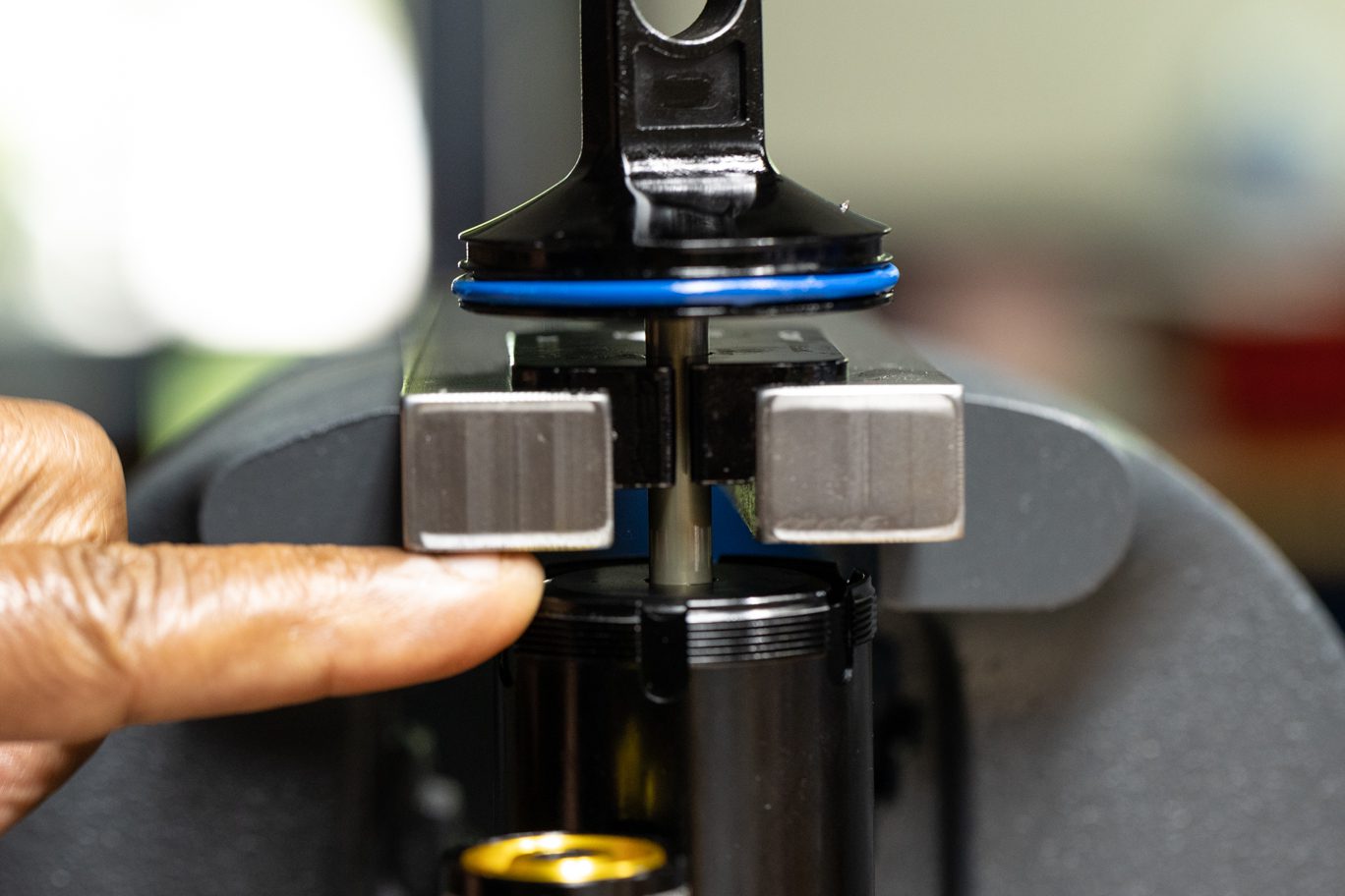
Clamp shaft in vise between end eye and inner air can.
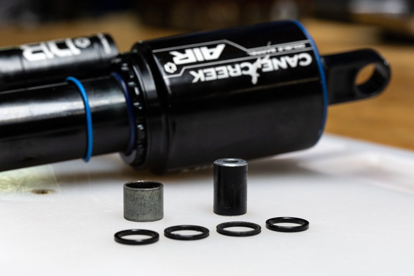
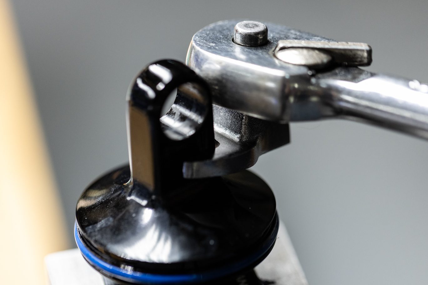
Using 1/2″ crowsfoot, unthread end eye from shaft. Remove stroke reduction and/or spacer (if present) and bottom out bumper. Remove inner air can. Pinch & remove and discard outer air can o-rings from inner air can and end eye.
TSB005 – DBair/DBair CS Stop Shim
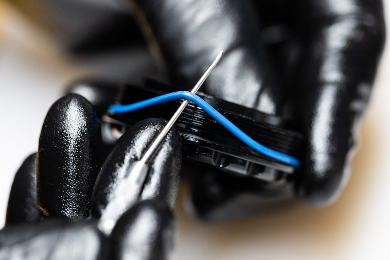
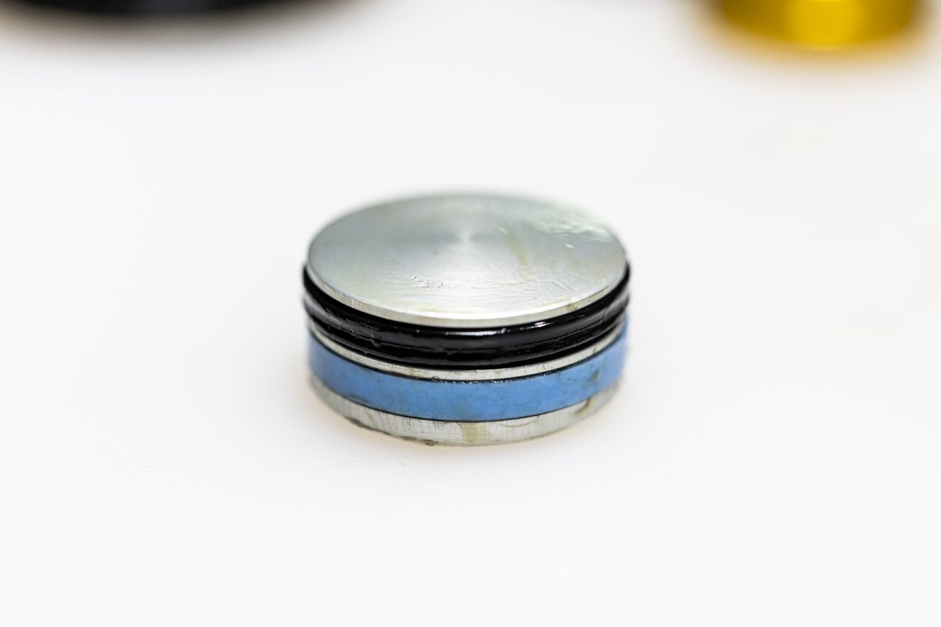
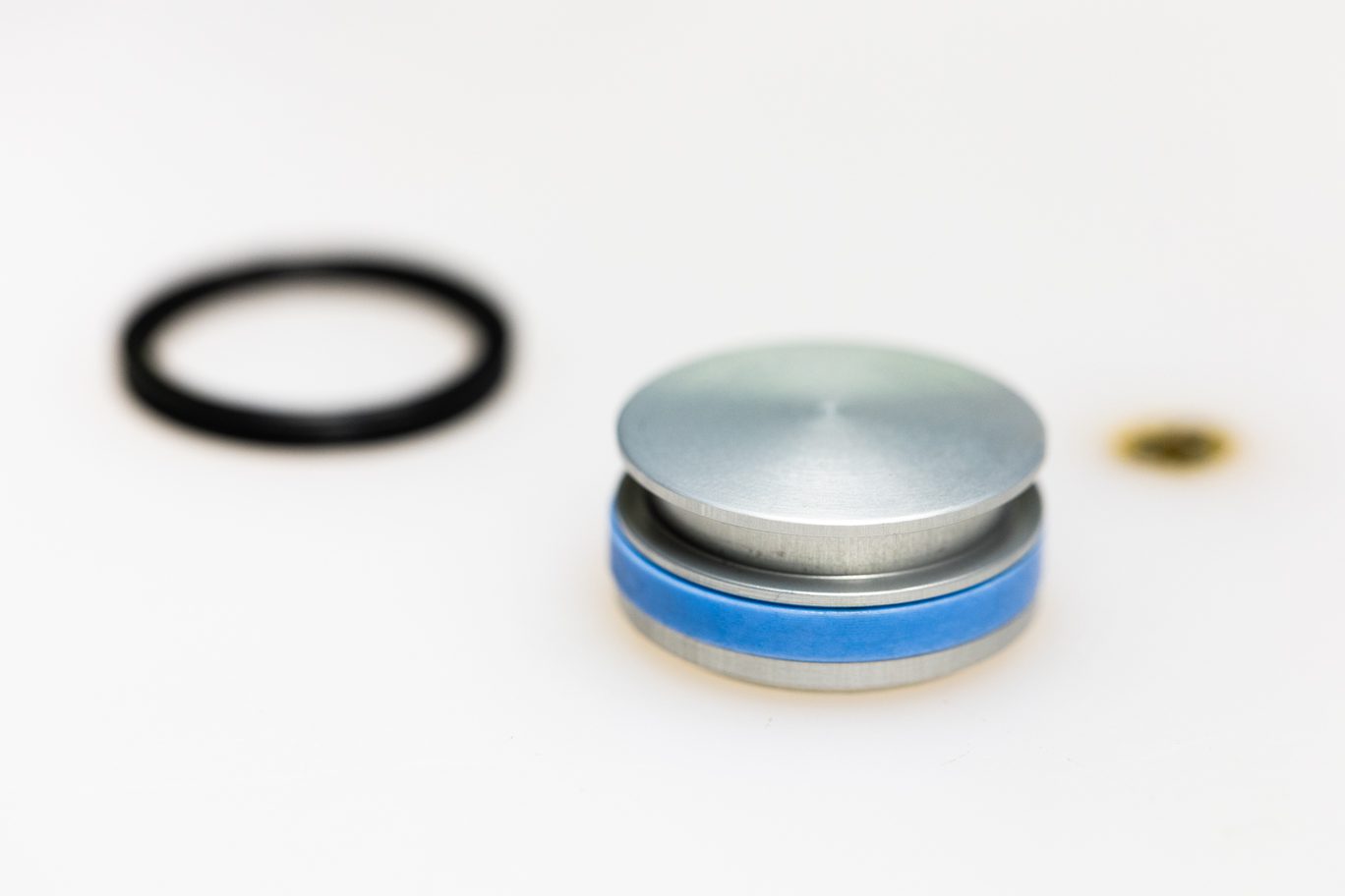
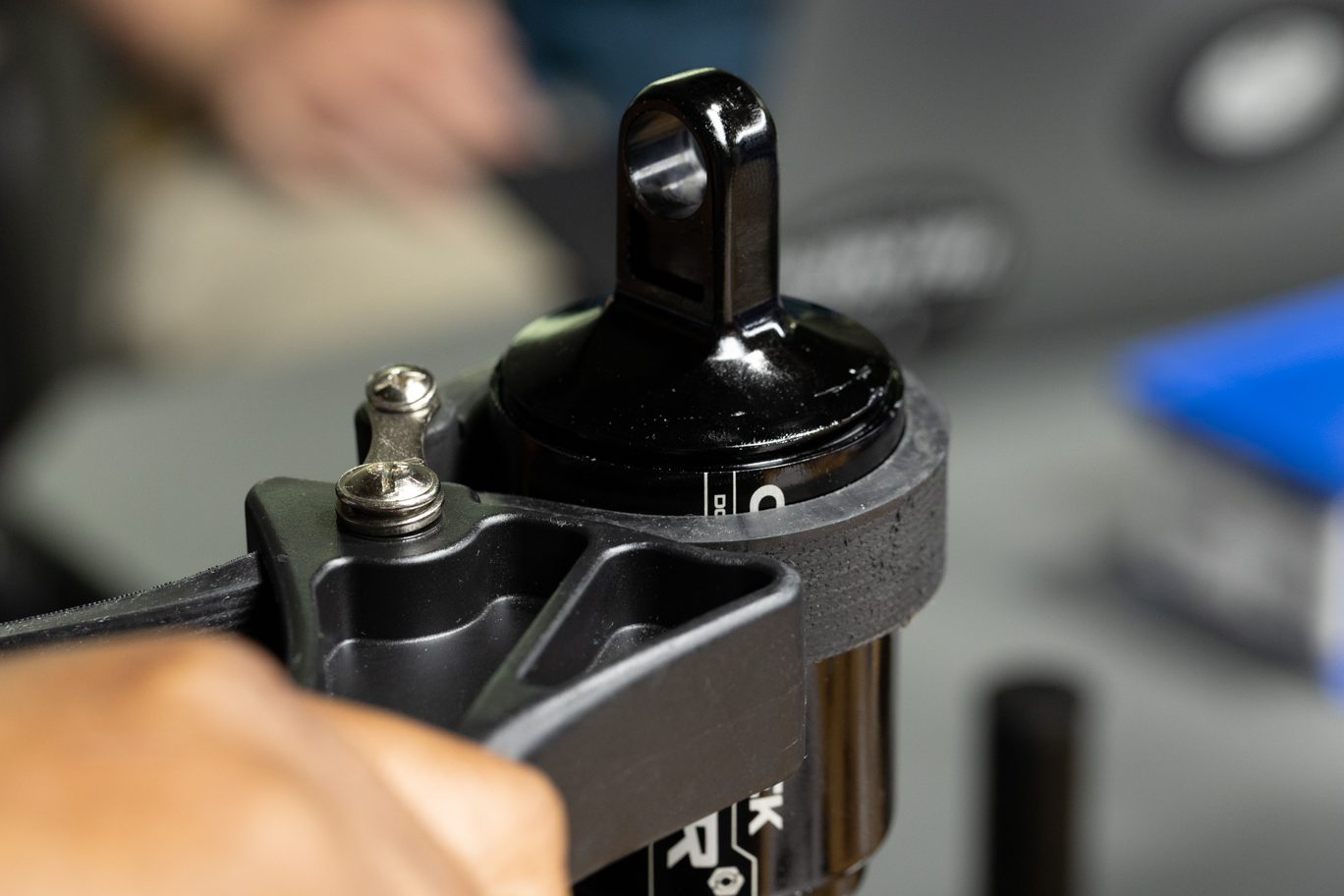
Clamp shock at valve body. Using T20, remove 3 air piston screws. Remove air piston. Remove and discard air piston o-ring, back up L-rings and quad ring.
TSB022 – DBair CS Air Piston Change
If gold piston is present, replace with a new, blue piston (AAD1796).
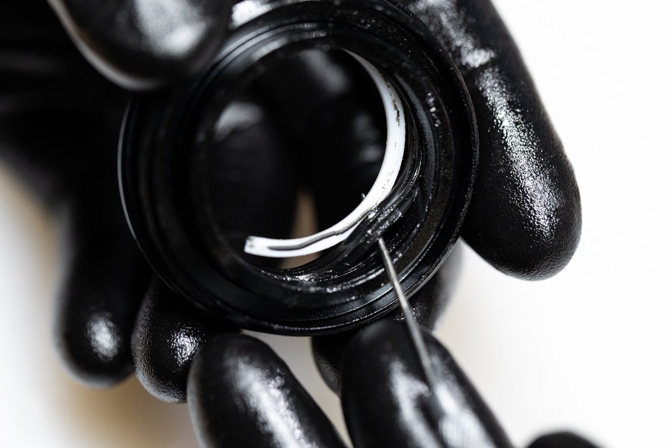
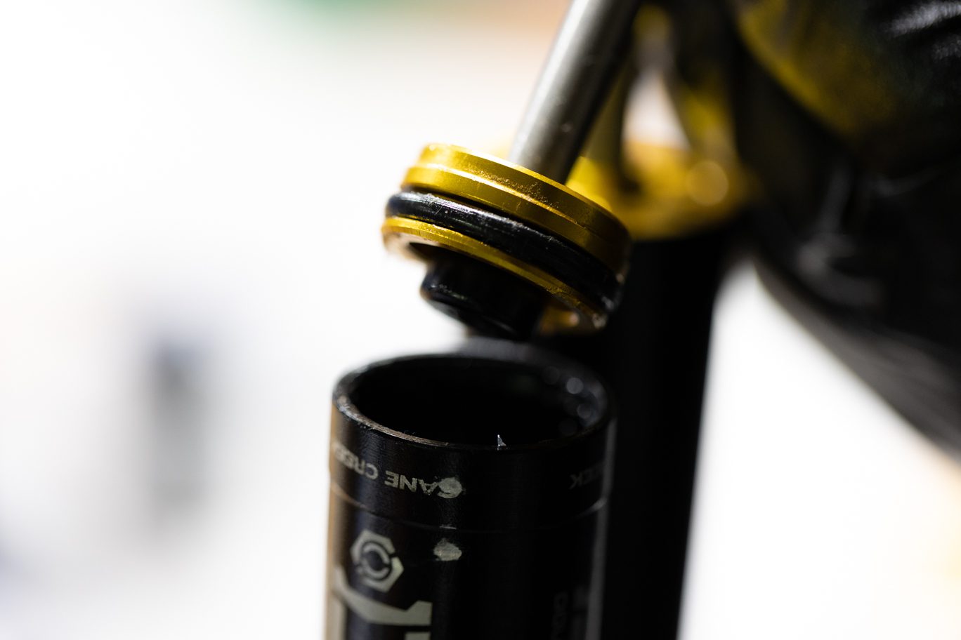
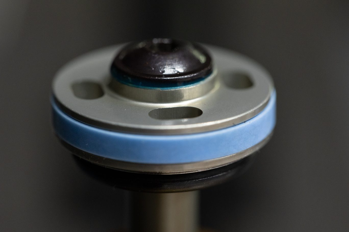
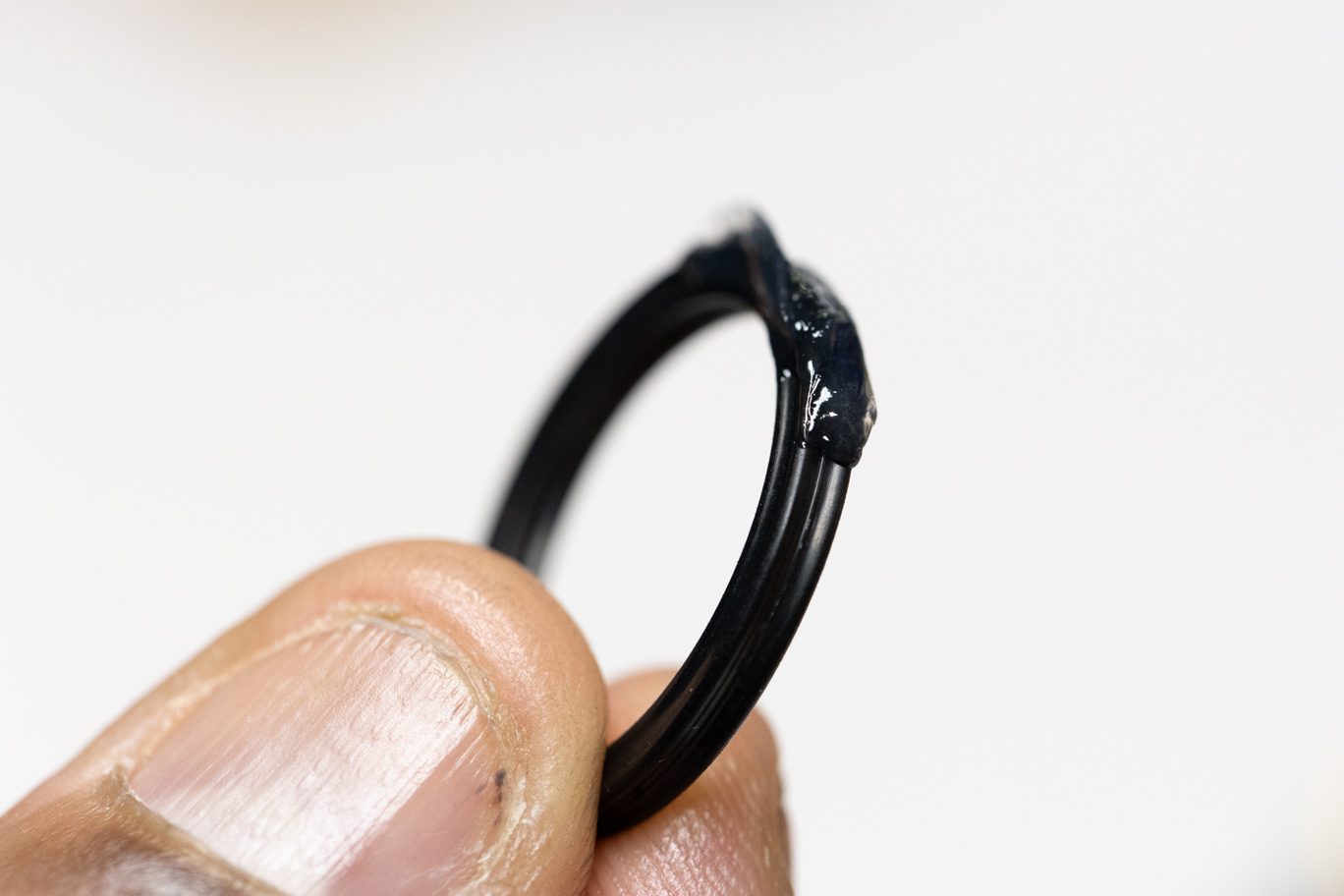
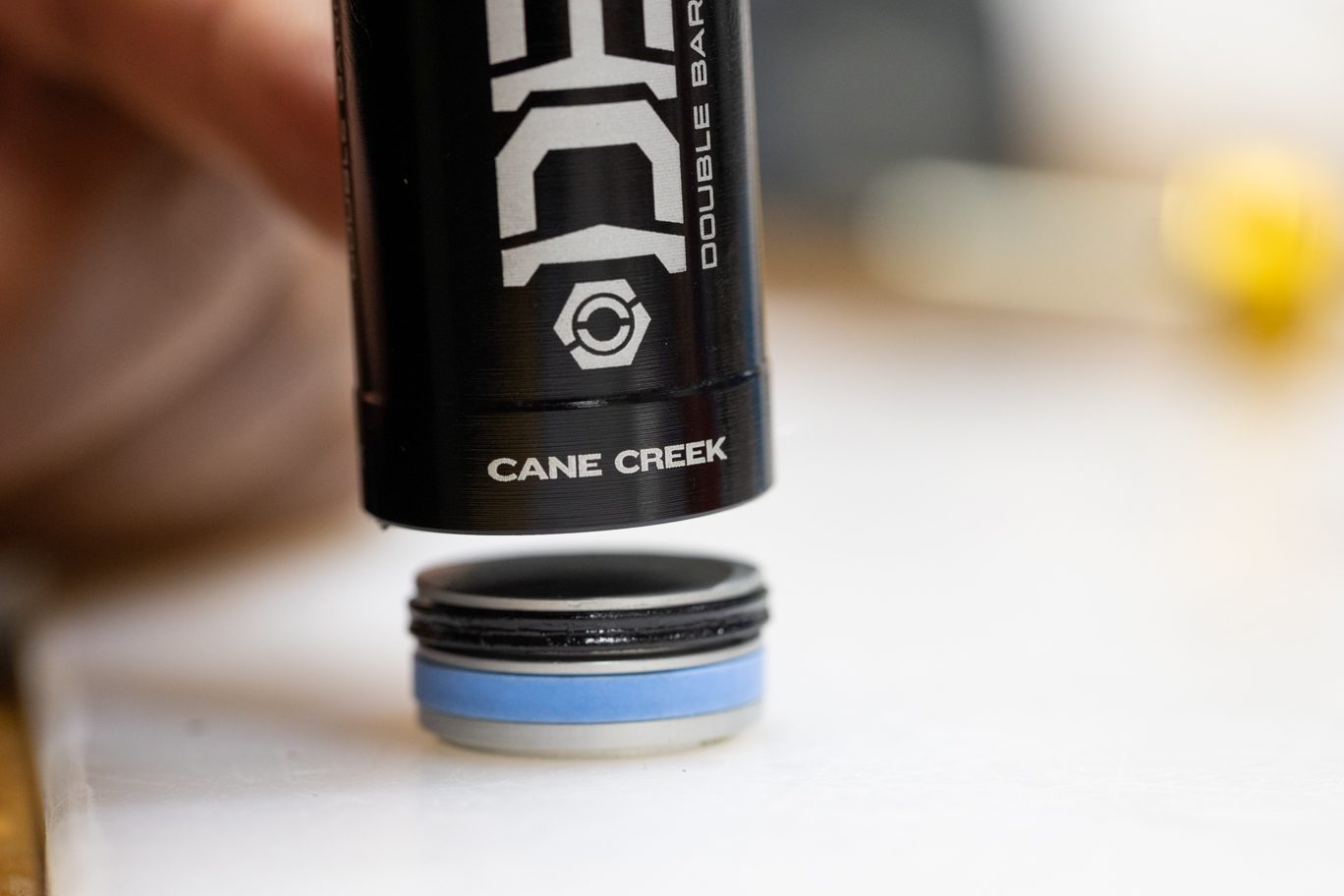
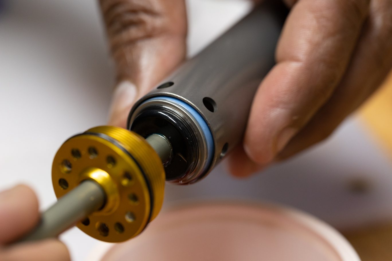
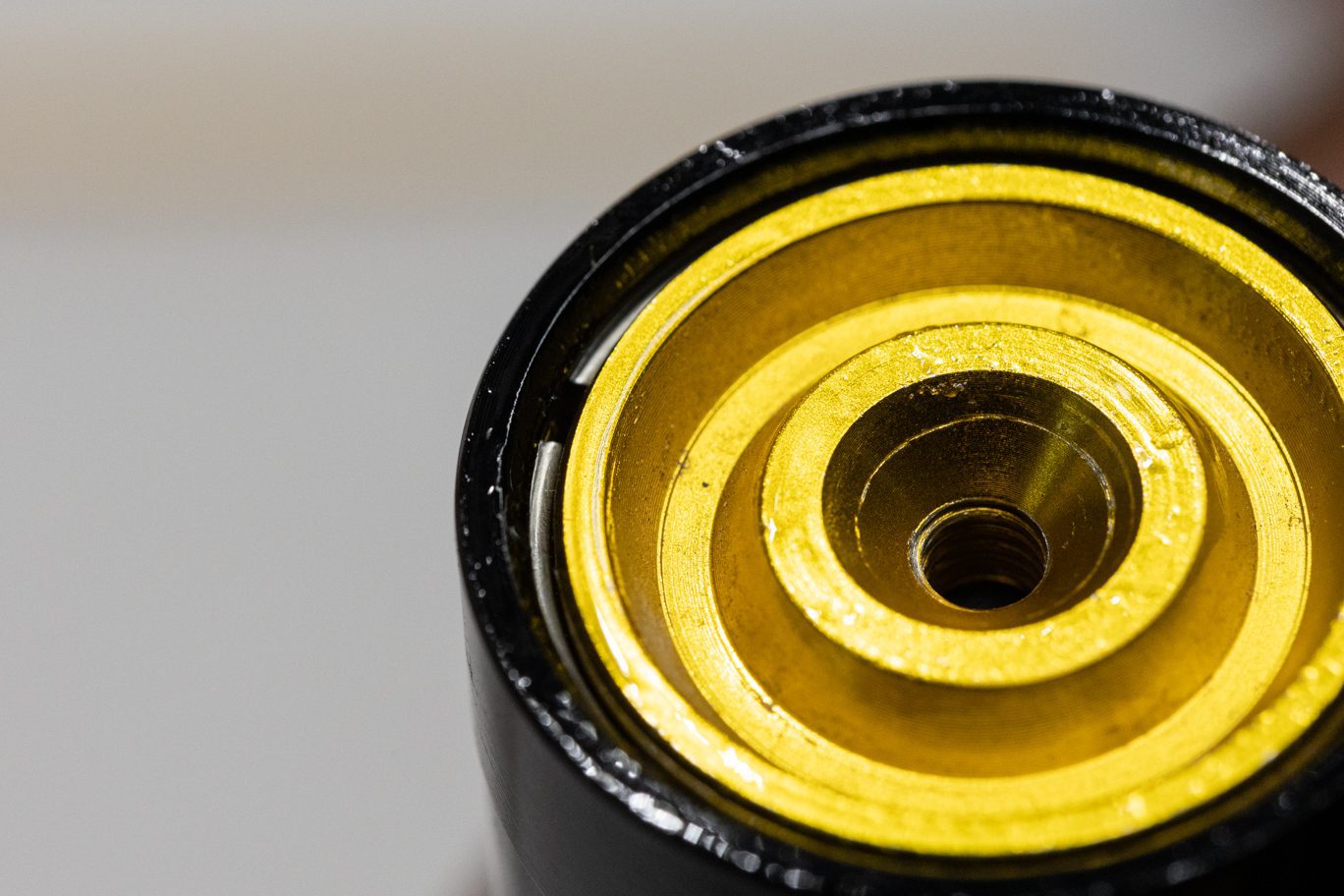
Remove air seal head from outer damper tube. Remove and discard wiper, air seal head o-ring, back up ring, quad ring and glide ring. Remove and discard sag o-ring from out damper tube.
TSB014 – DBair/DBair CS Air Seal Head Quad Ring Change
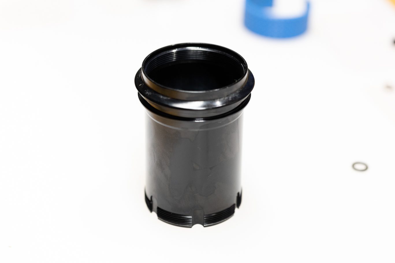
Thoroughly inspect damper tube and res tube. Replace if necessary. Test tightness of outer damper tube and reservoir tube. If either comes loose without much force, remove completely. Otherwise, only remove if replacing.
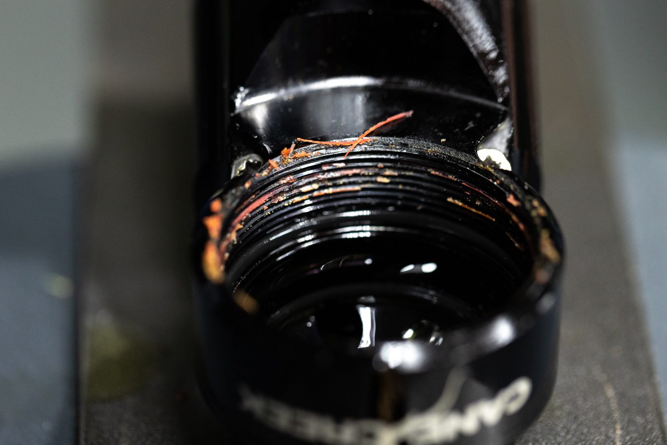
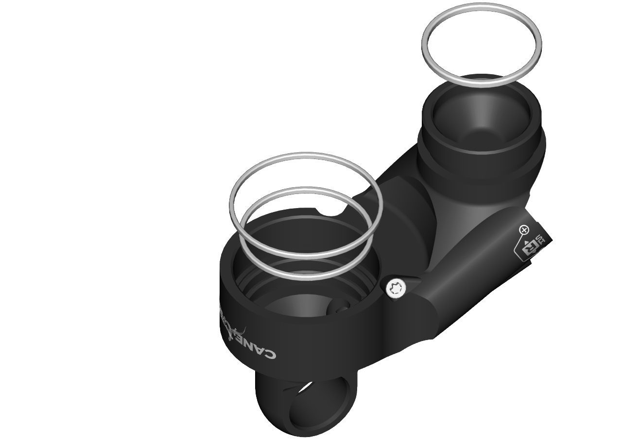
With outer damper tube and/or res tube removed, remove and discard o-rings. Thoroughly clean all Loctite residue from cylinder head threads.
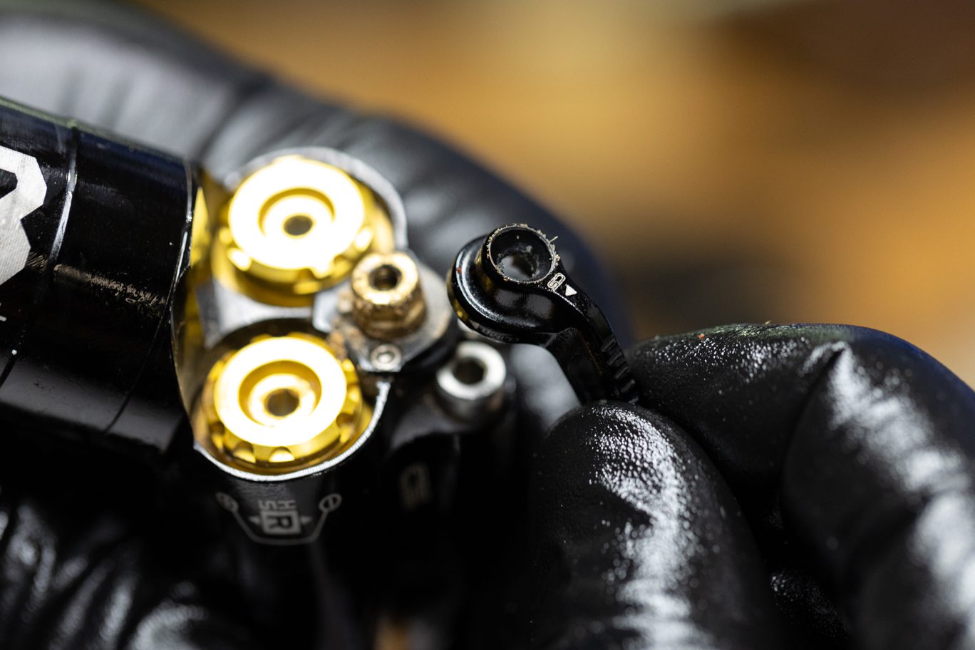
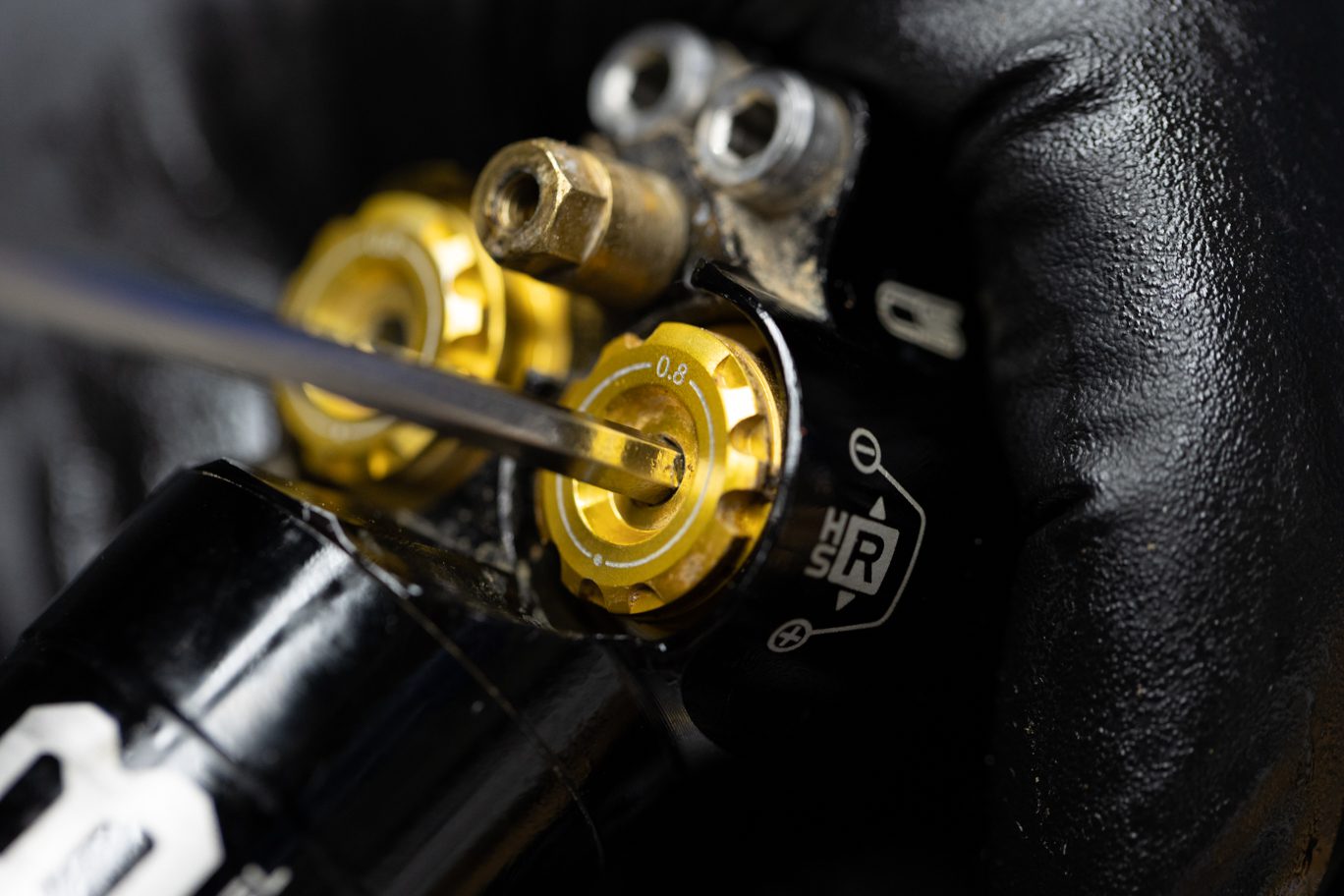
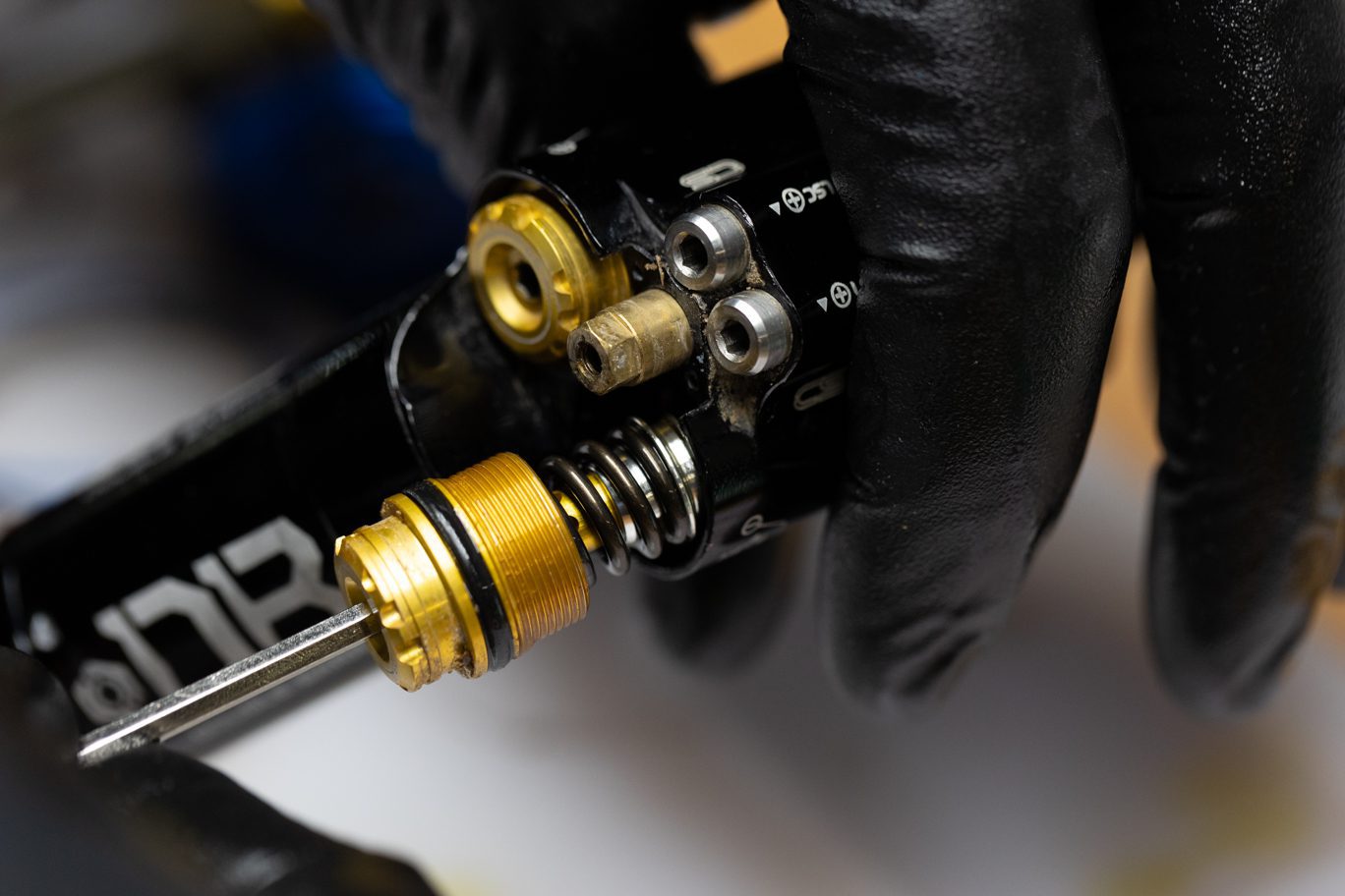
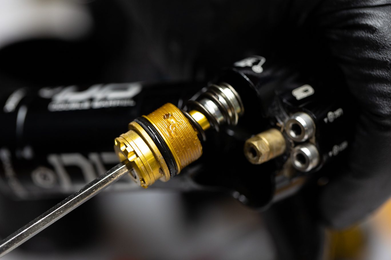
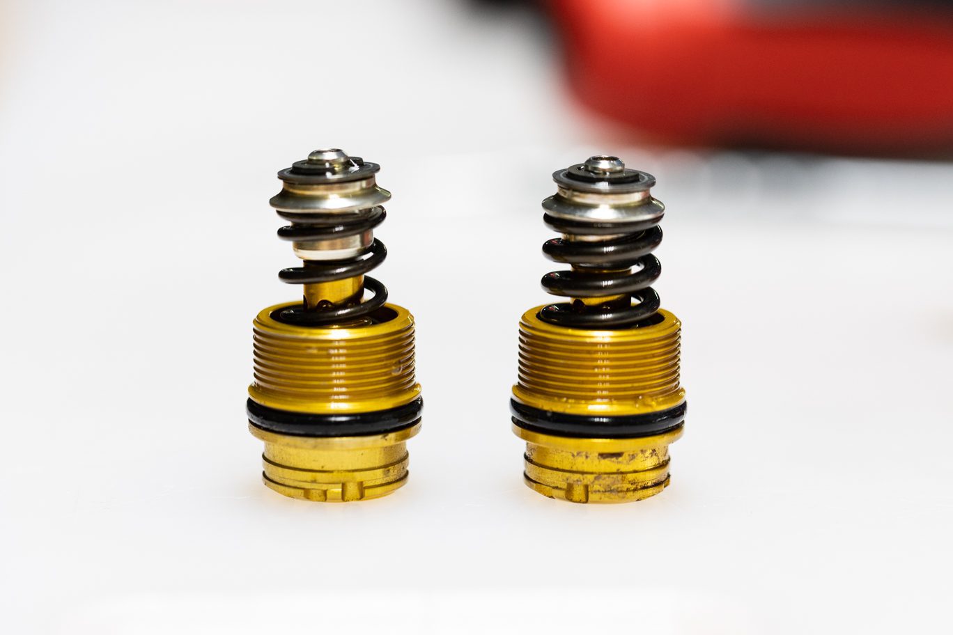
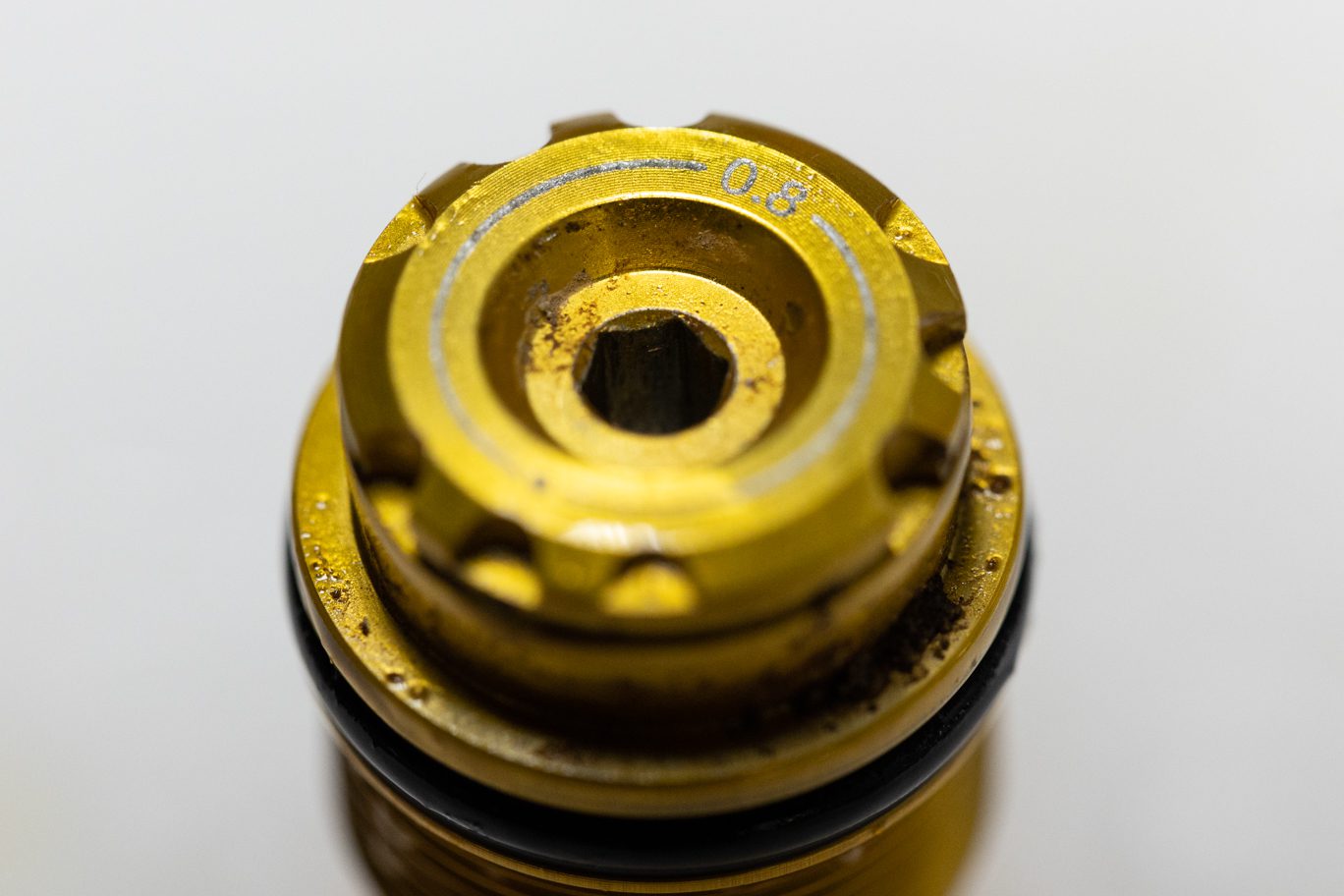
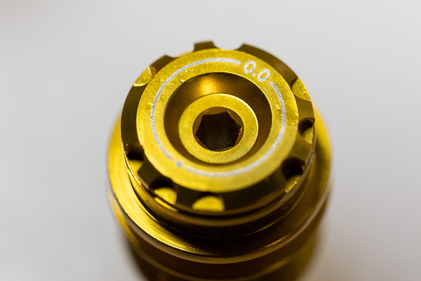
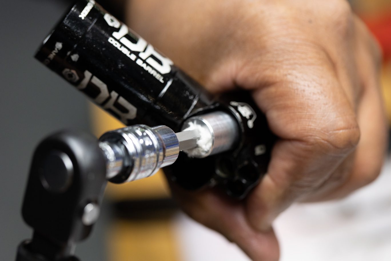
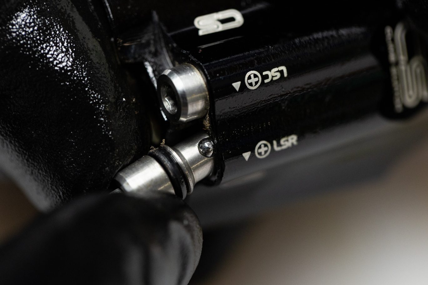
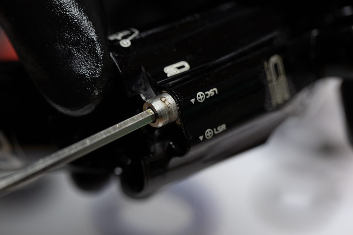
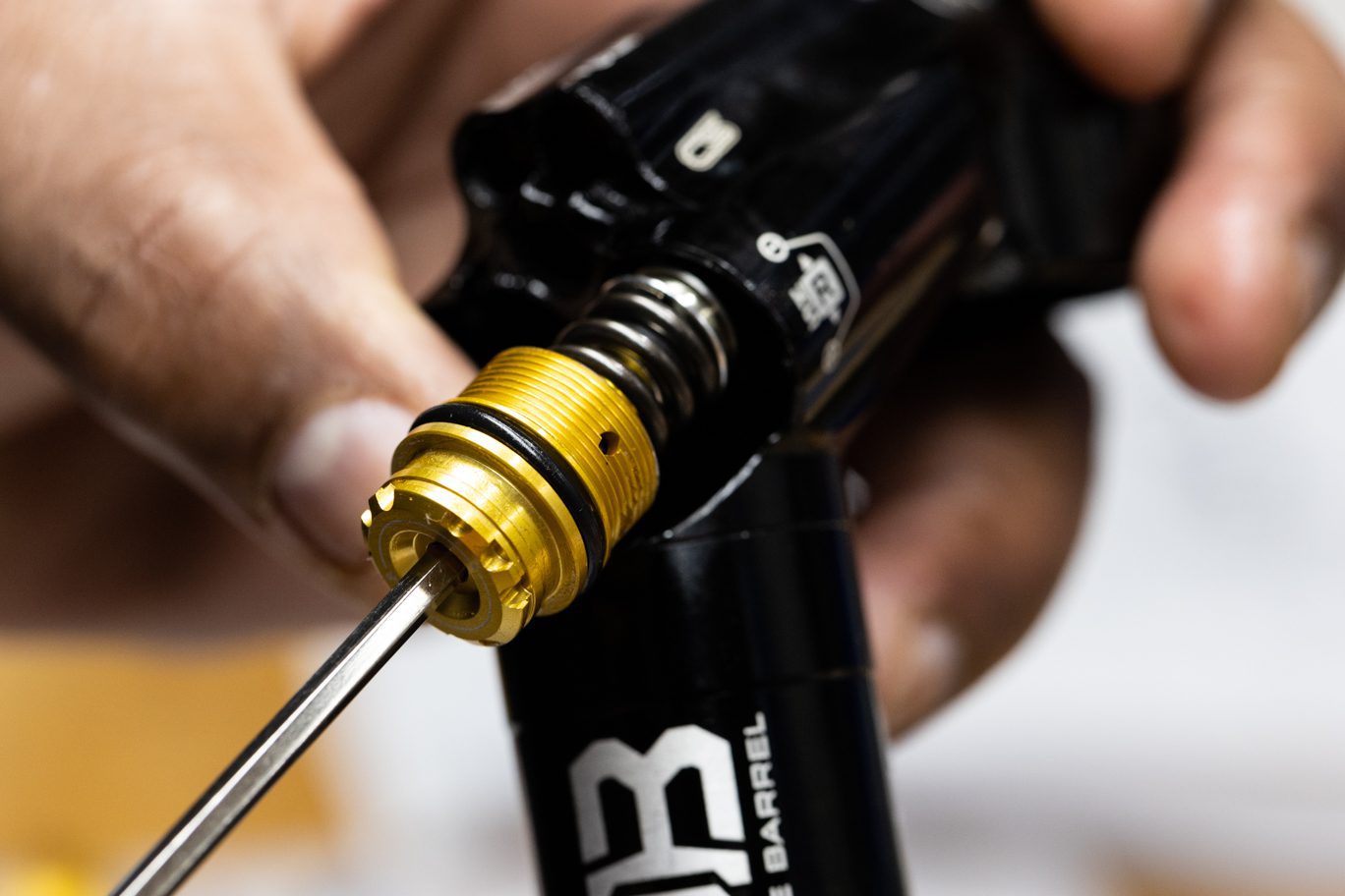
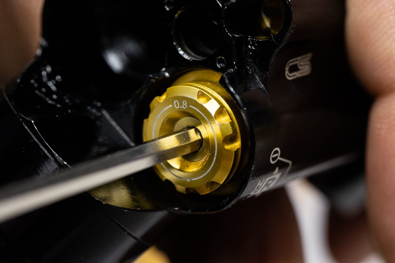
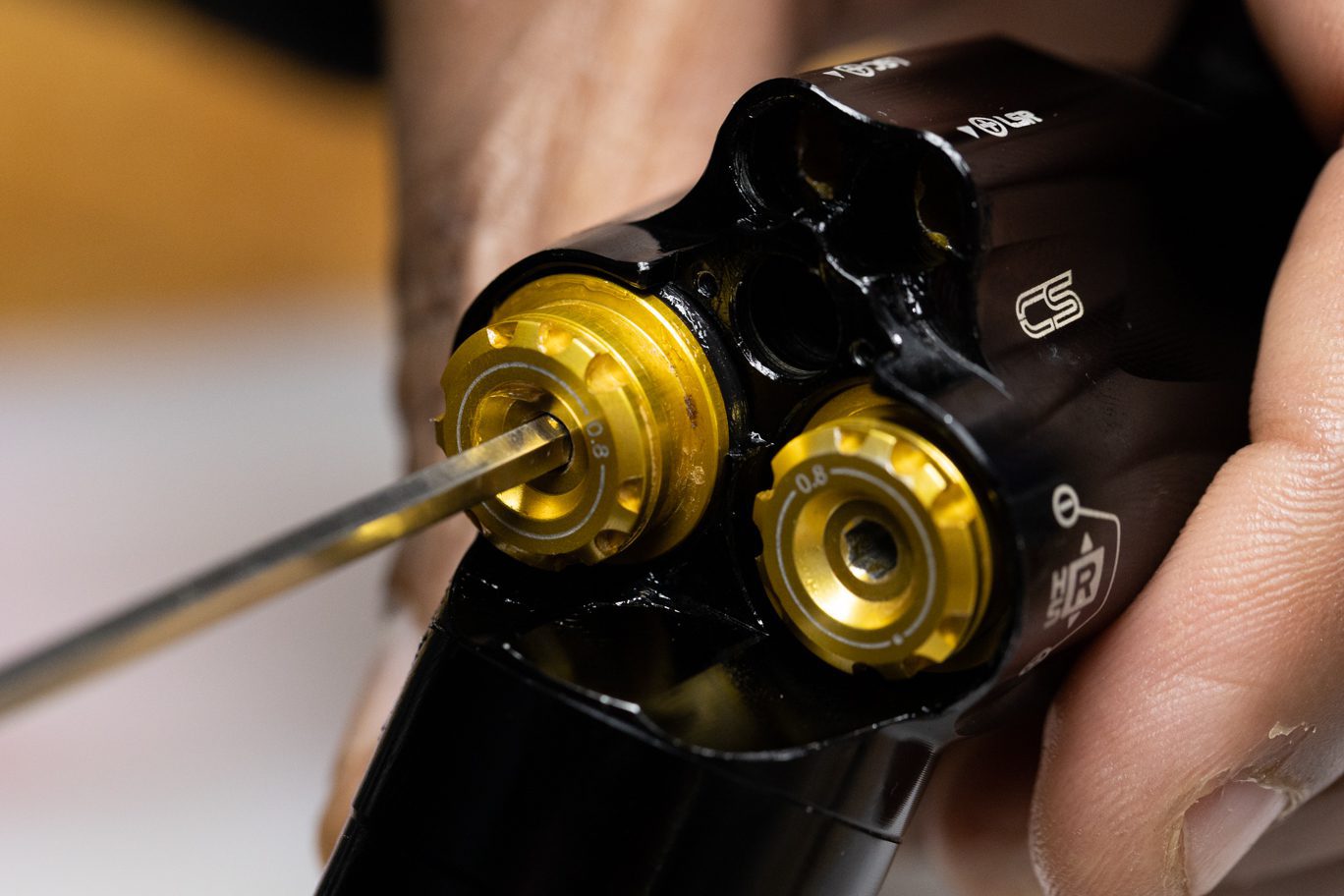
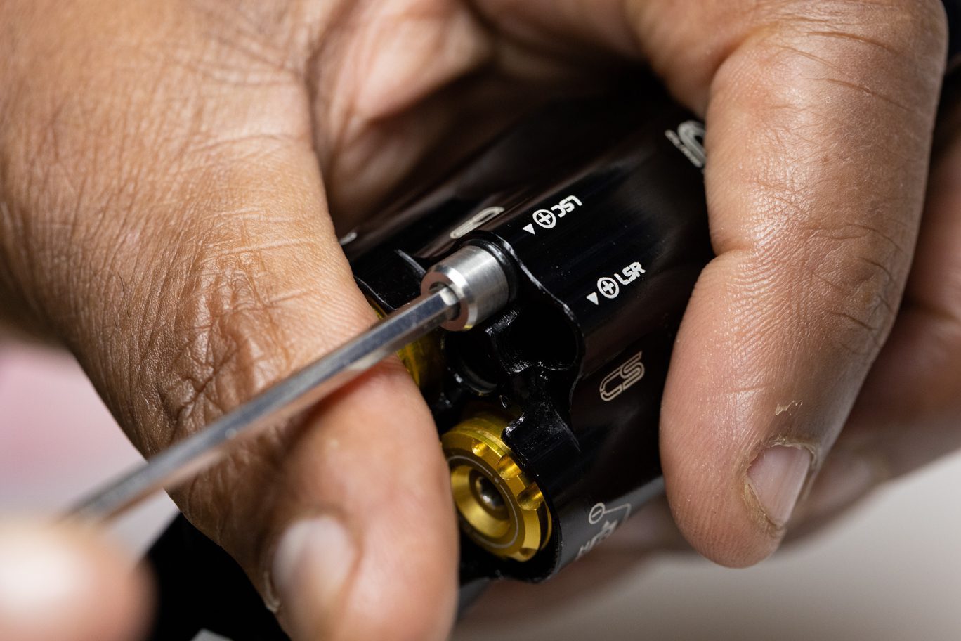
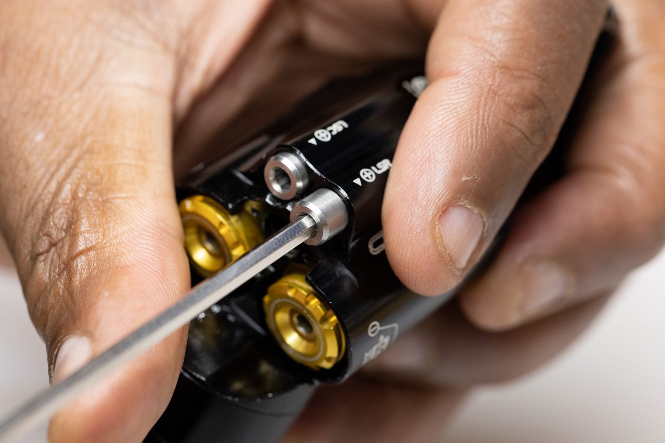
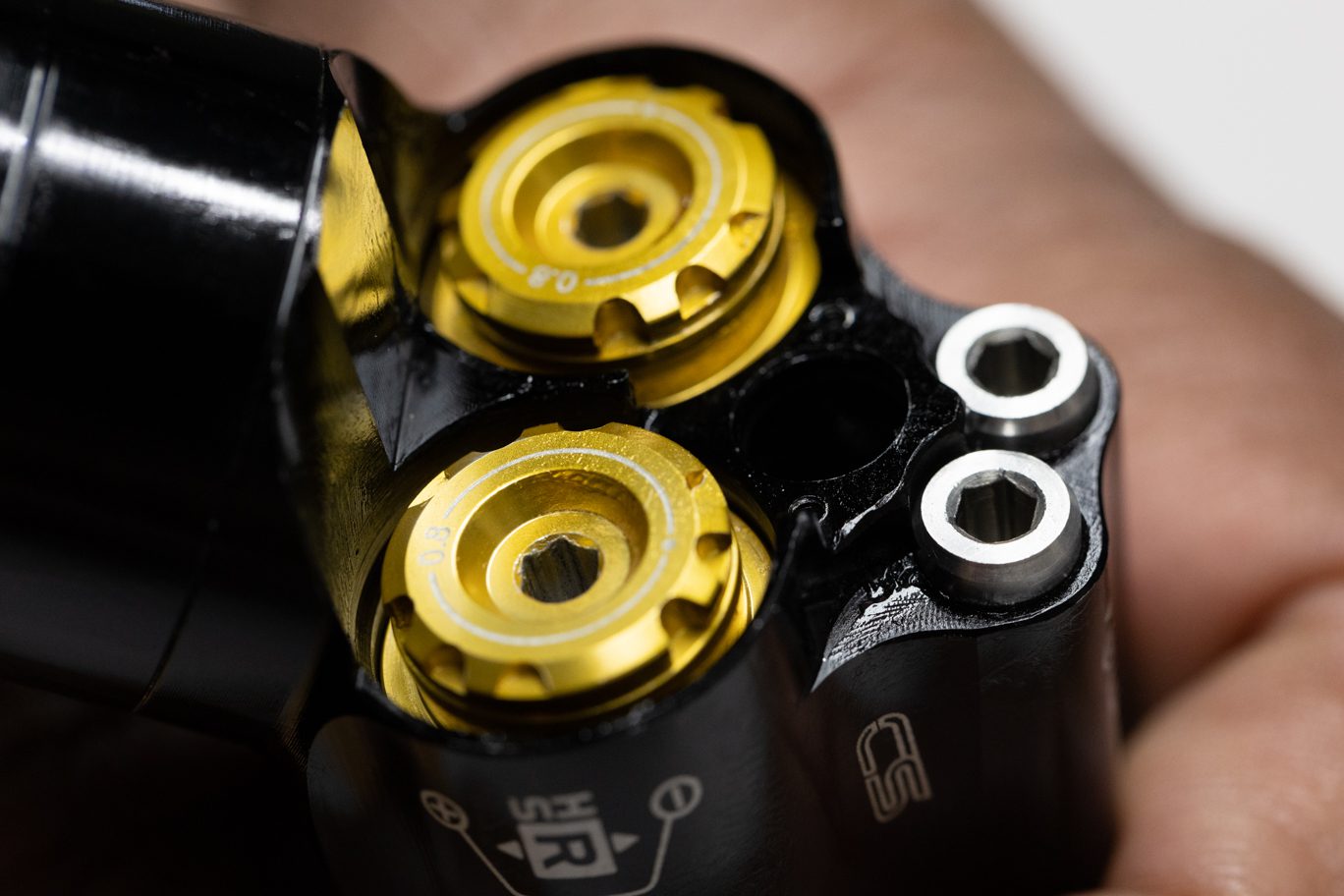
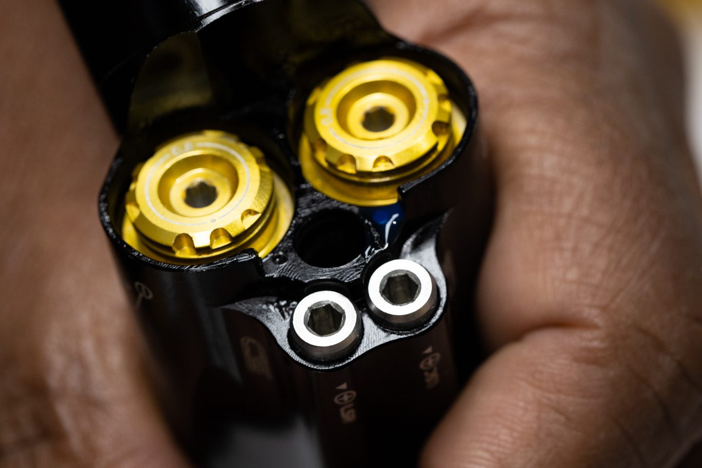
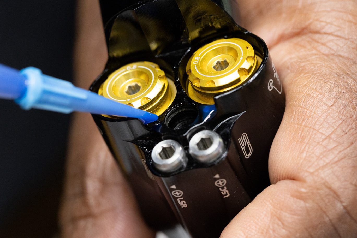
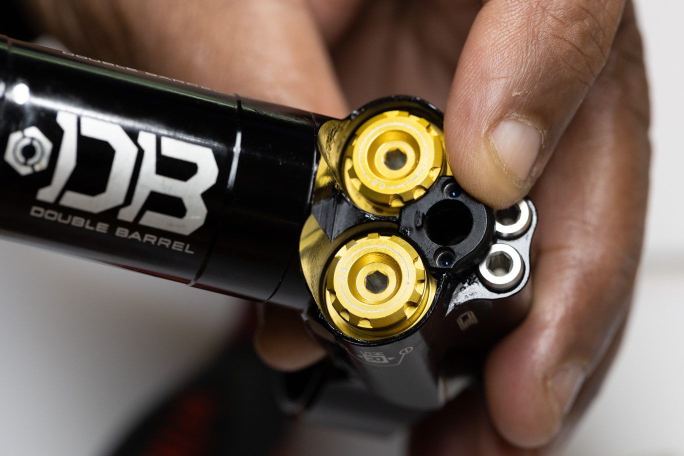
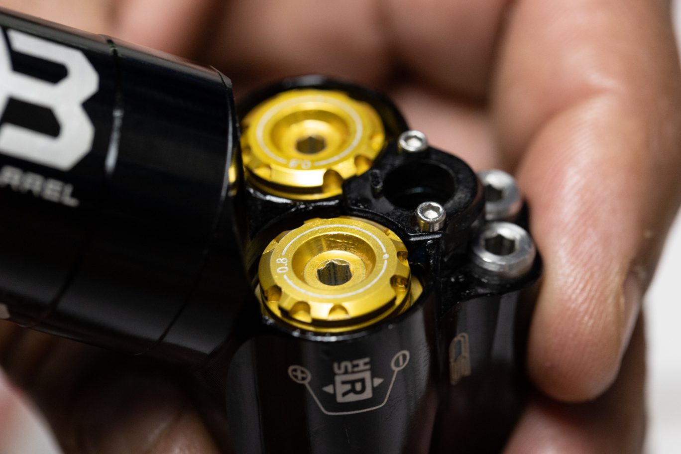
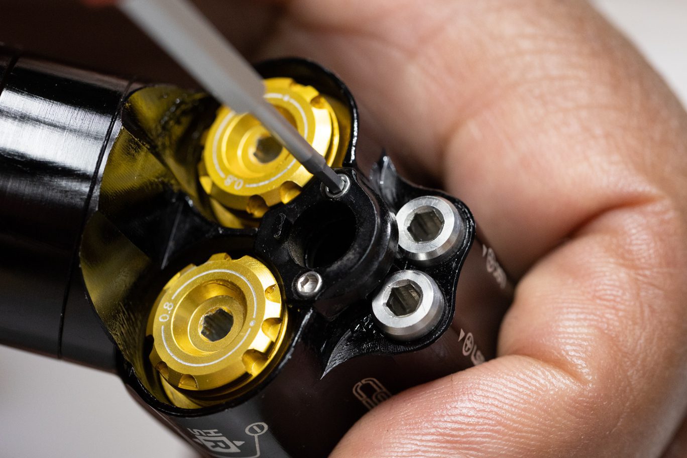
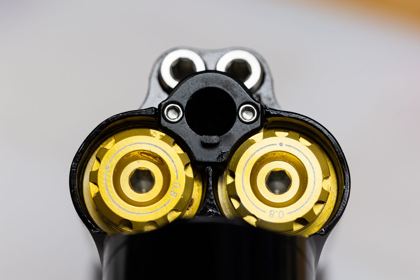
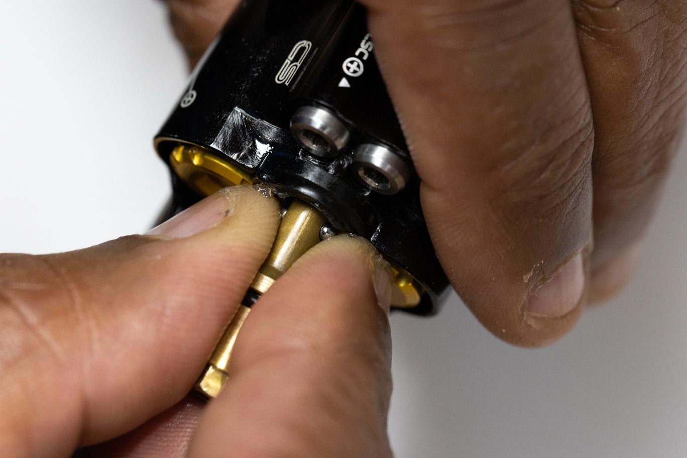
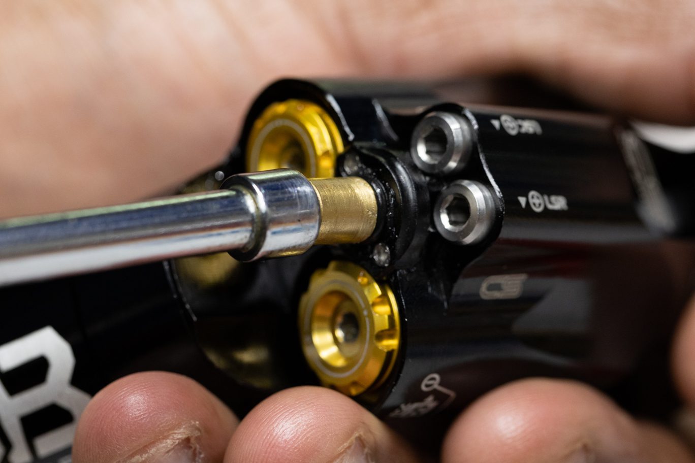
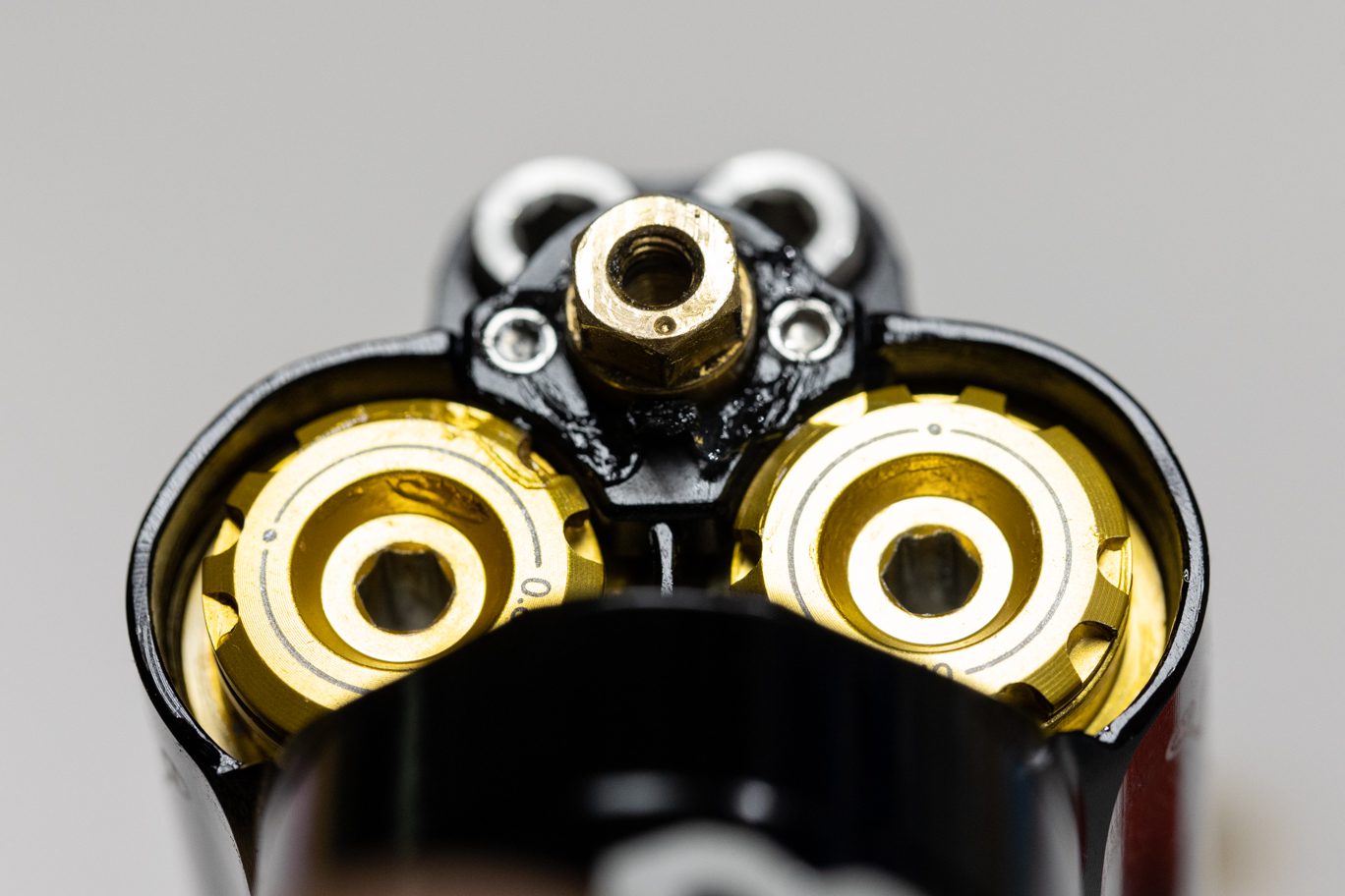
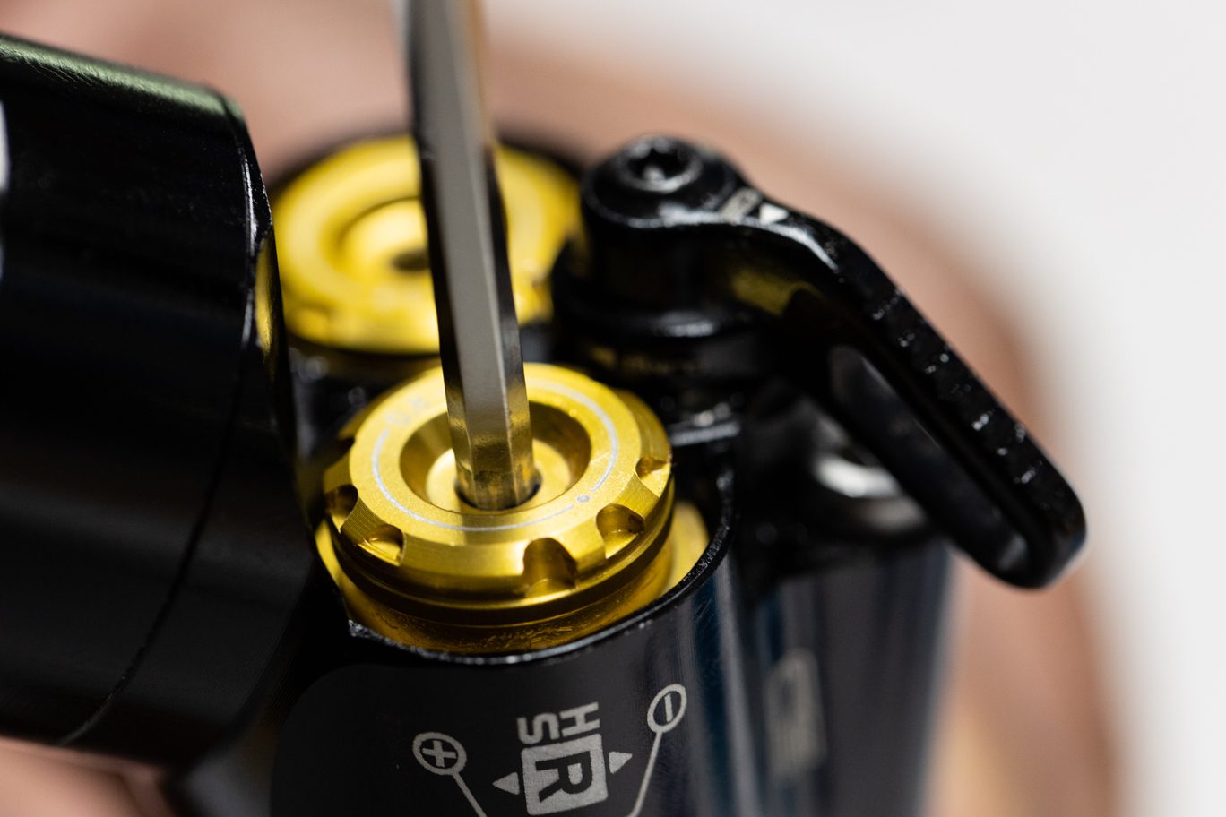
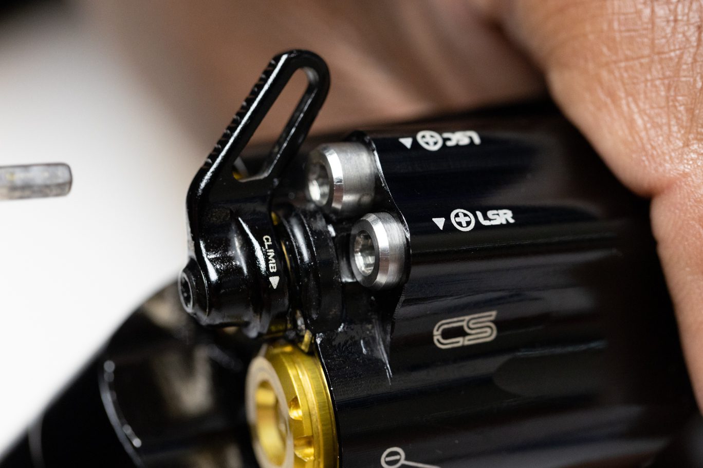
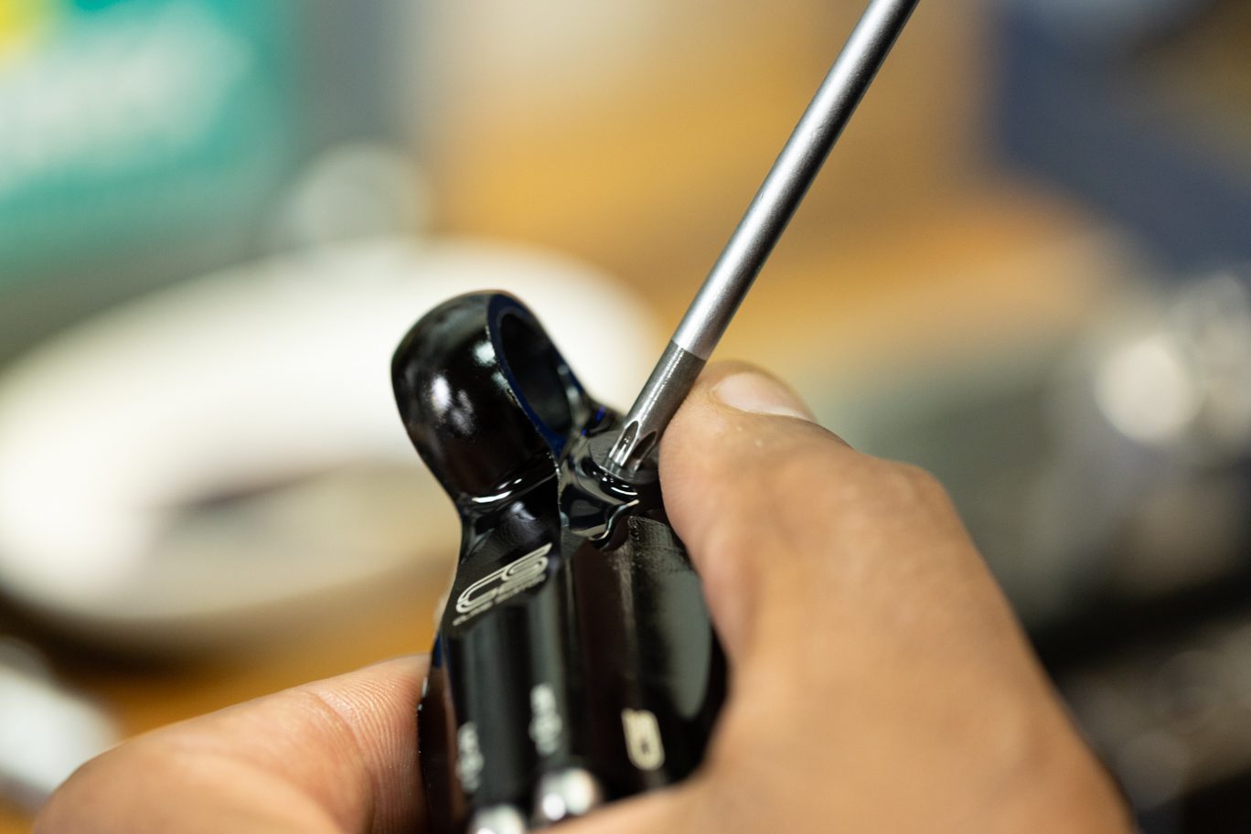
Using 3mm Allen, remove High Speed adjusters. Take note of the Rebound adjuster (0.8 with port) and spring (red, 30wt weight) and Compression adjuster (will vary from 0.0 without port, to 0.8, 1.0 or 1.2 with port) and spring (yellow, 10wt or standard 20wt). Spring color may have worn off. Pinch & remove and discard High Speed adjuster o-rings.
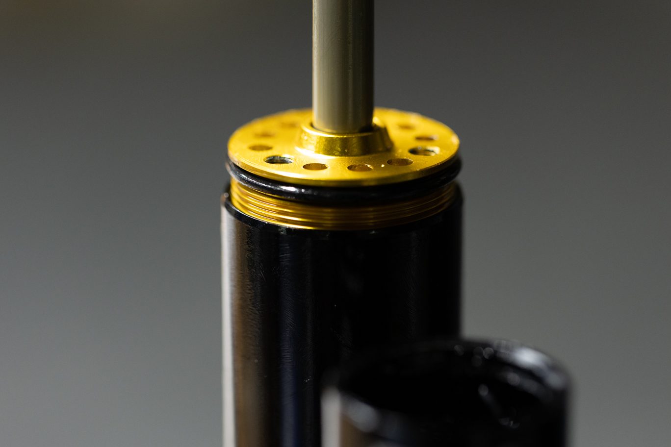
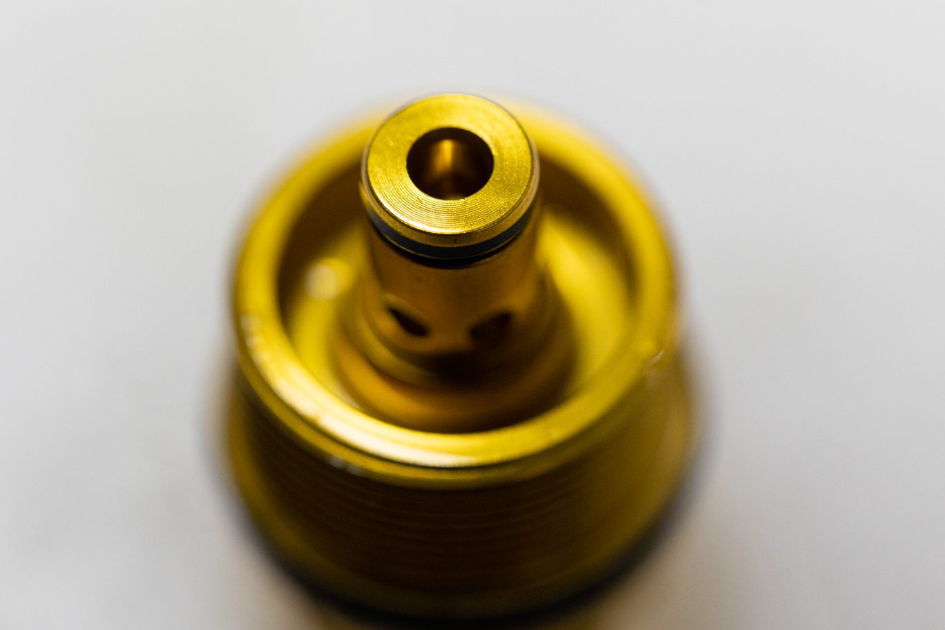
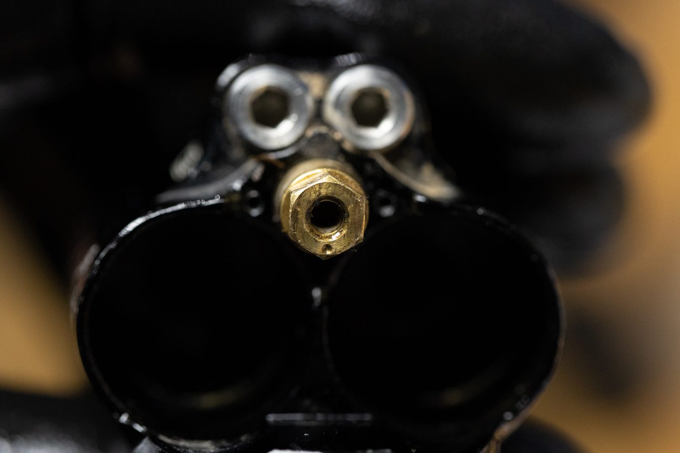
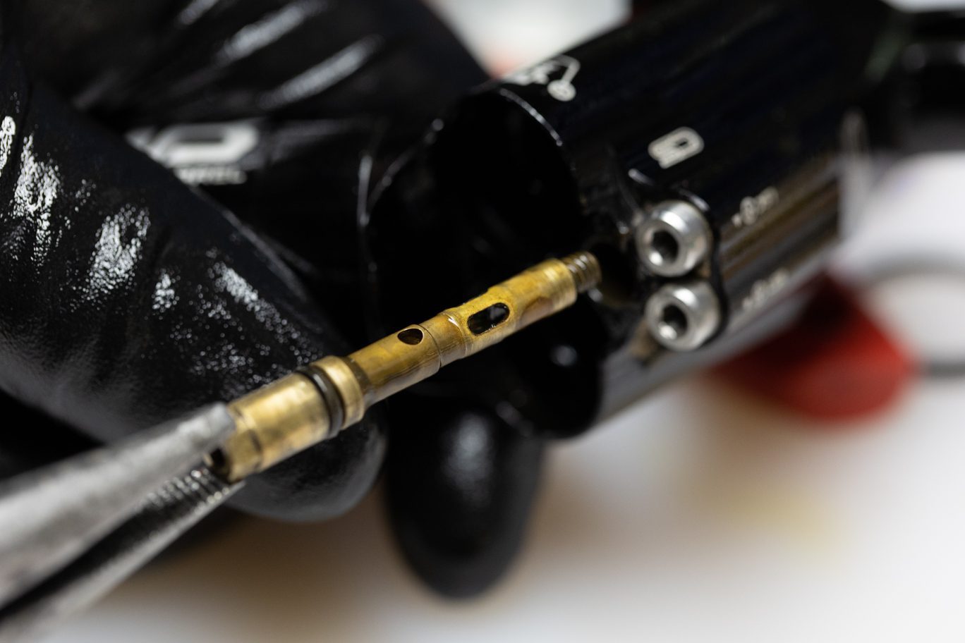
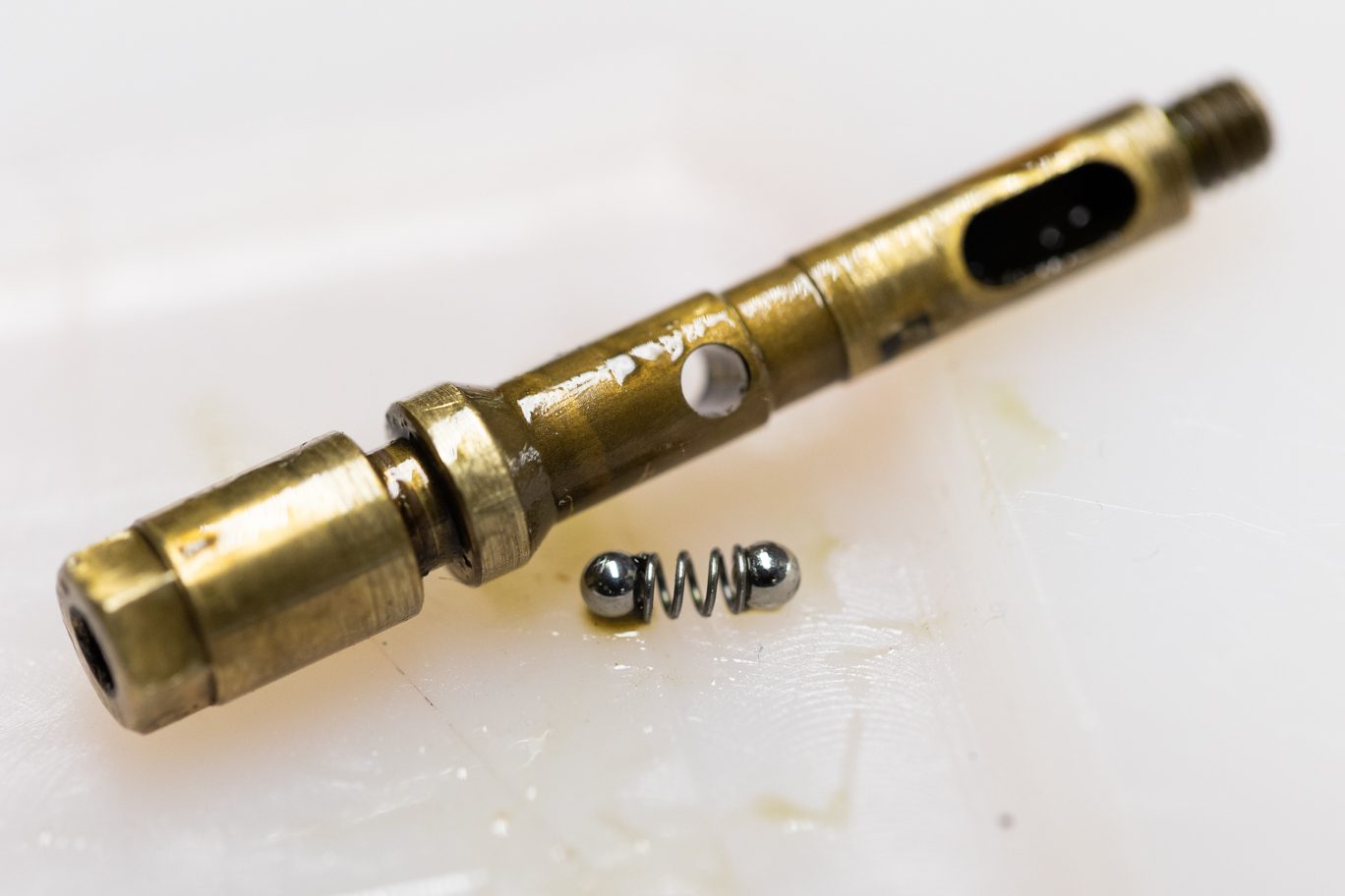
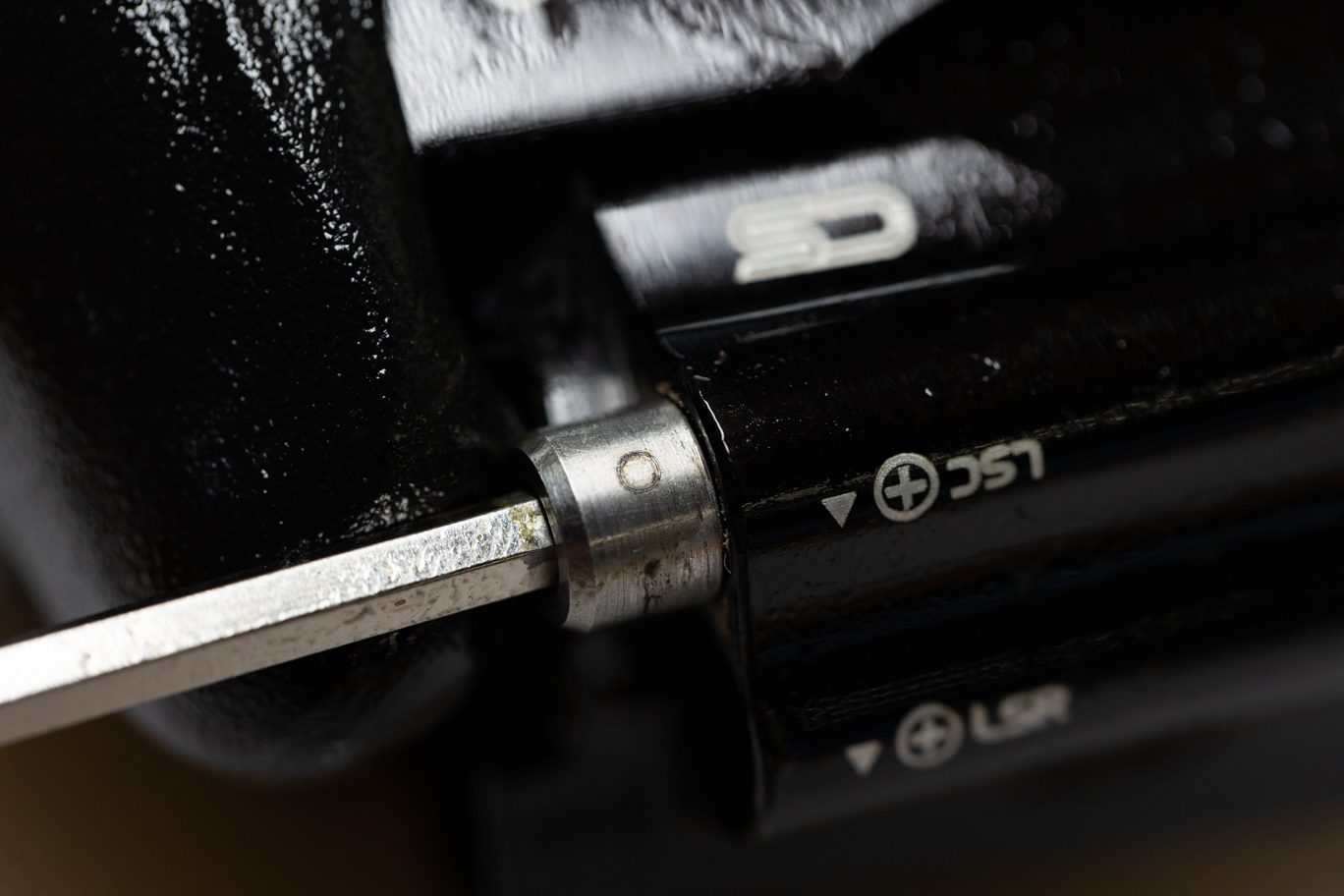
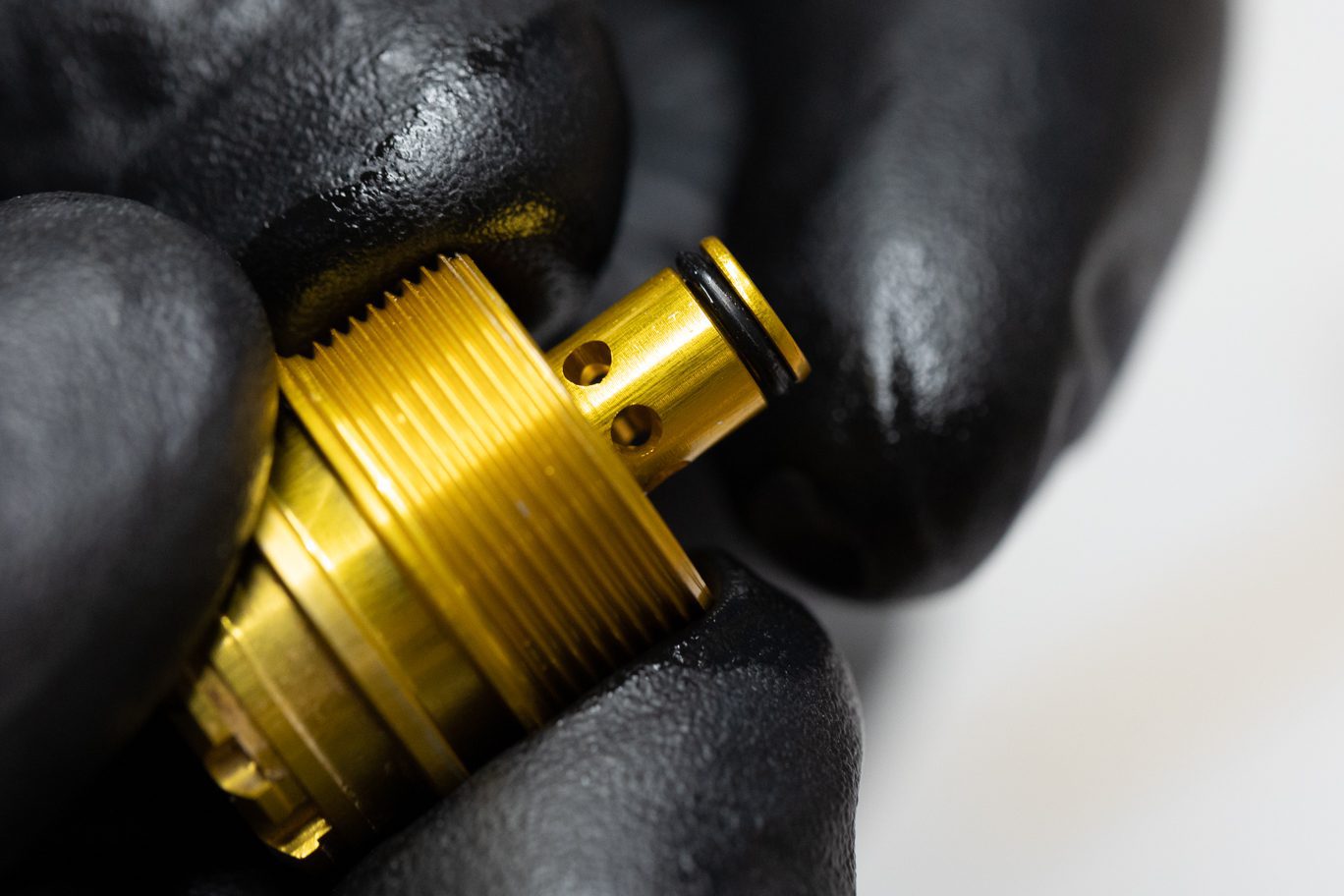
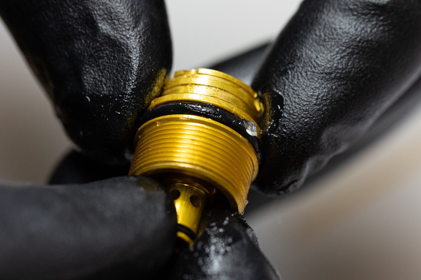
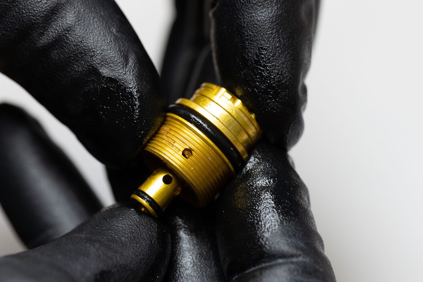
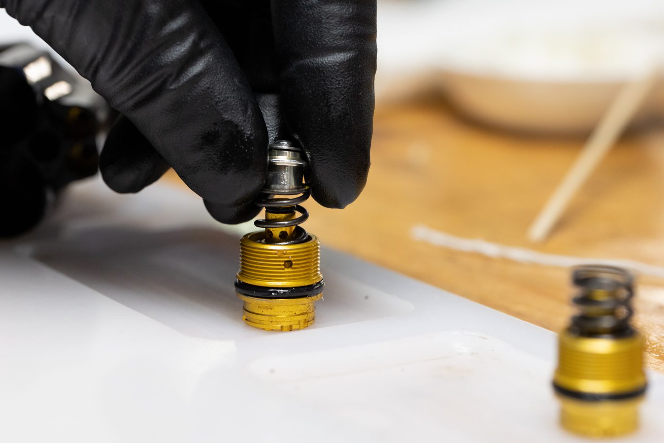
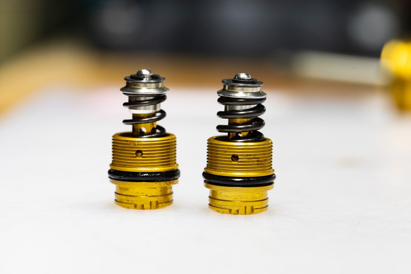
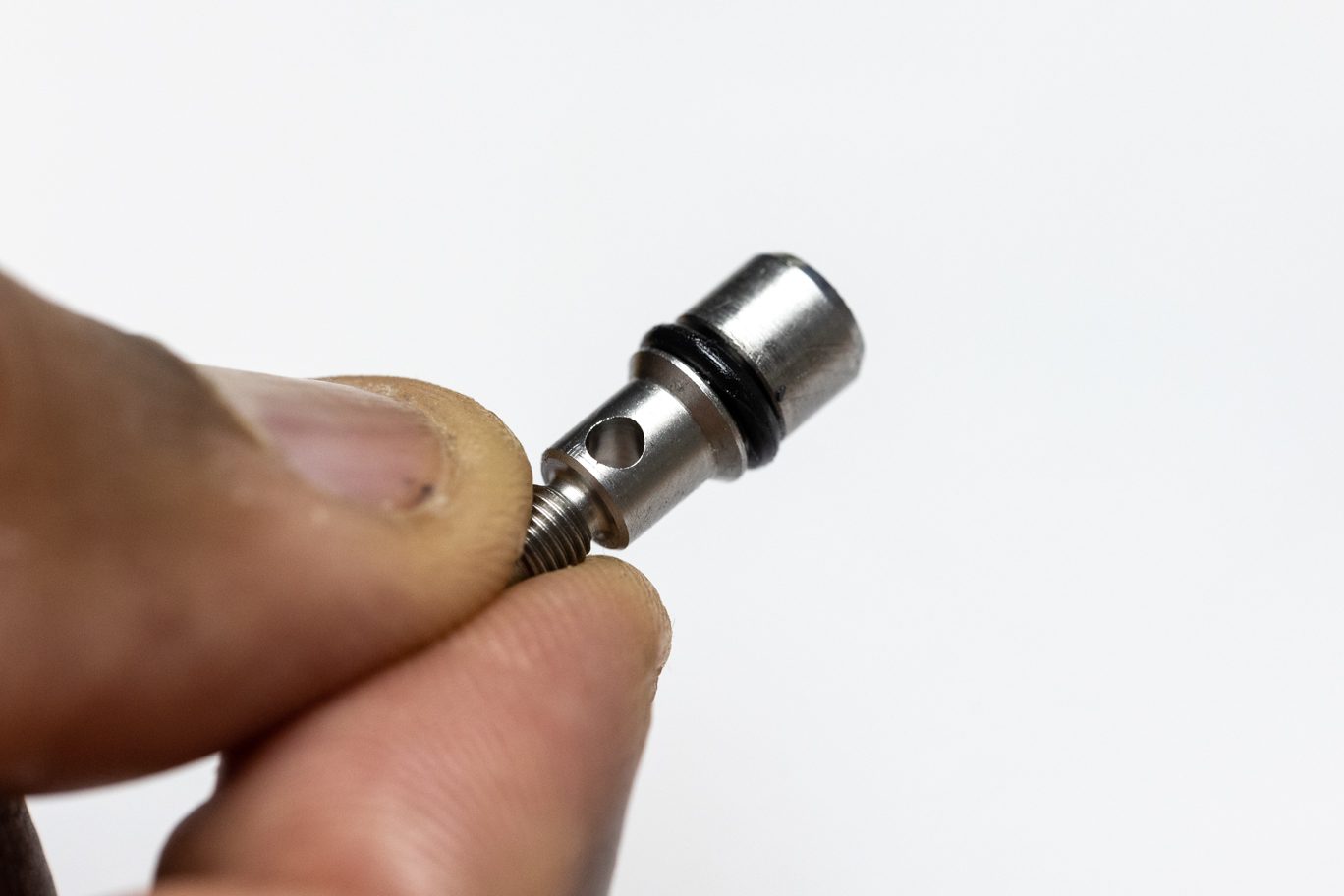
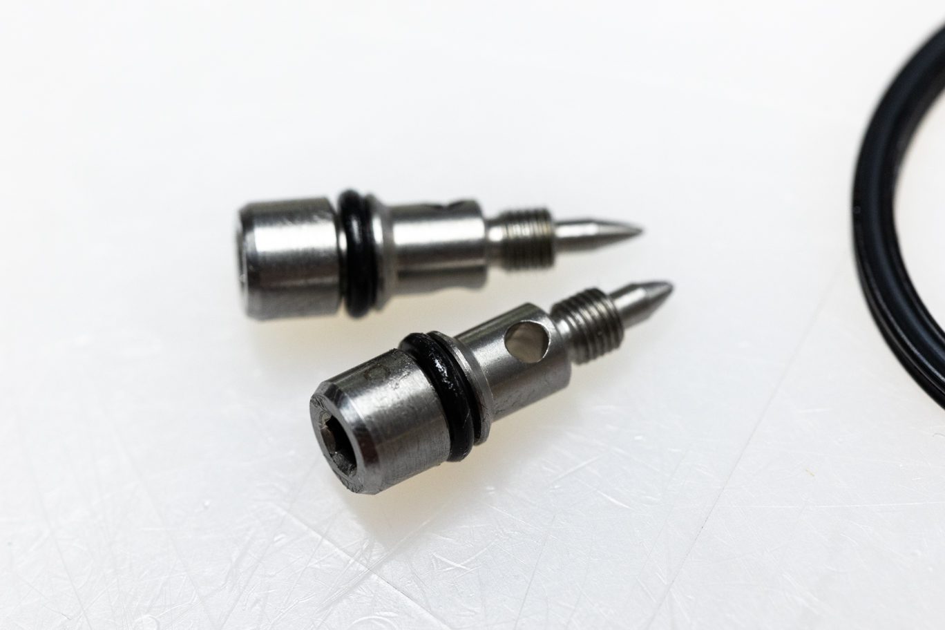
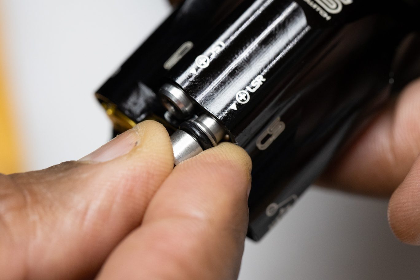
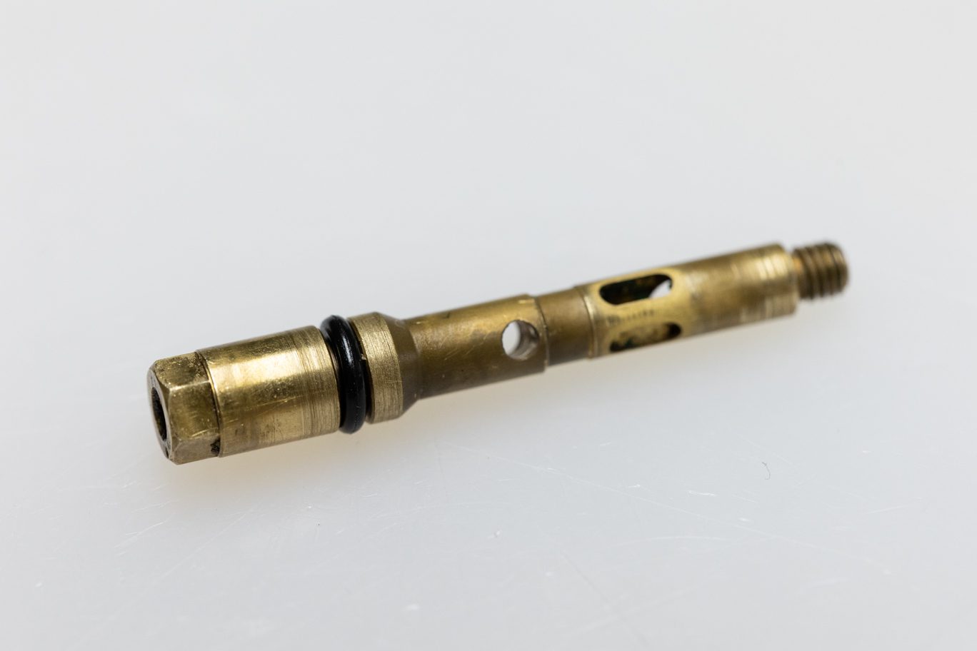
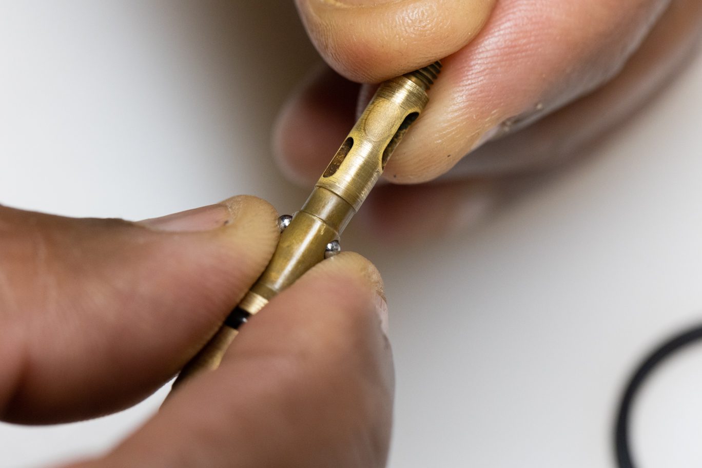
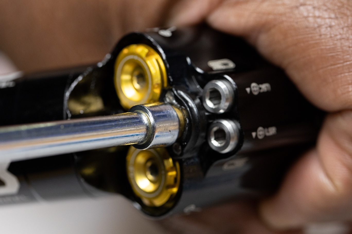
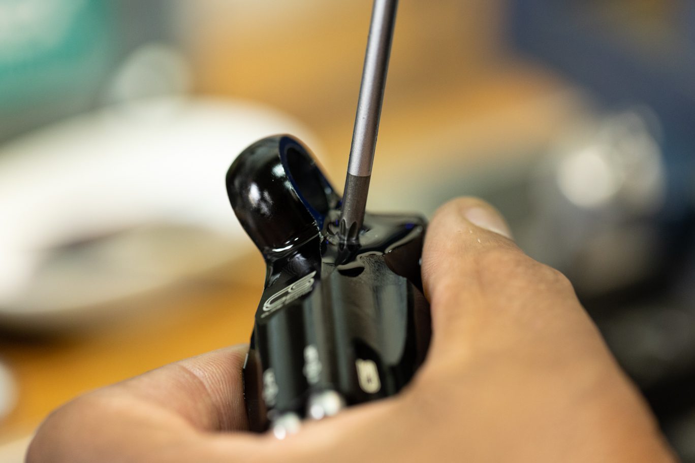
Using 6mm socket, thread spool valve closed (clockwise) and note location of the indicator dot. Then open (counterclockwise) the valve at least half a turn and then onto indicator dot at the 6:00 position. This is the default setting for reassembly. Make note of this postion from fully closed. Unthread and remove spool valve assembly. Pliers may be necessary to remove assembly once completely unthreaded. Remove and discard spool valve o-ring. Remove and clean detent balls and spring.
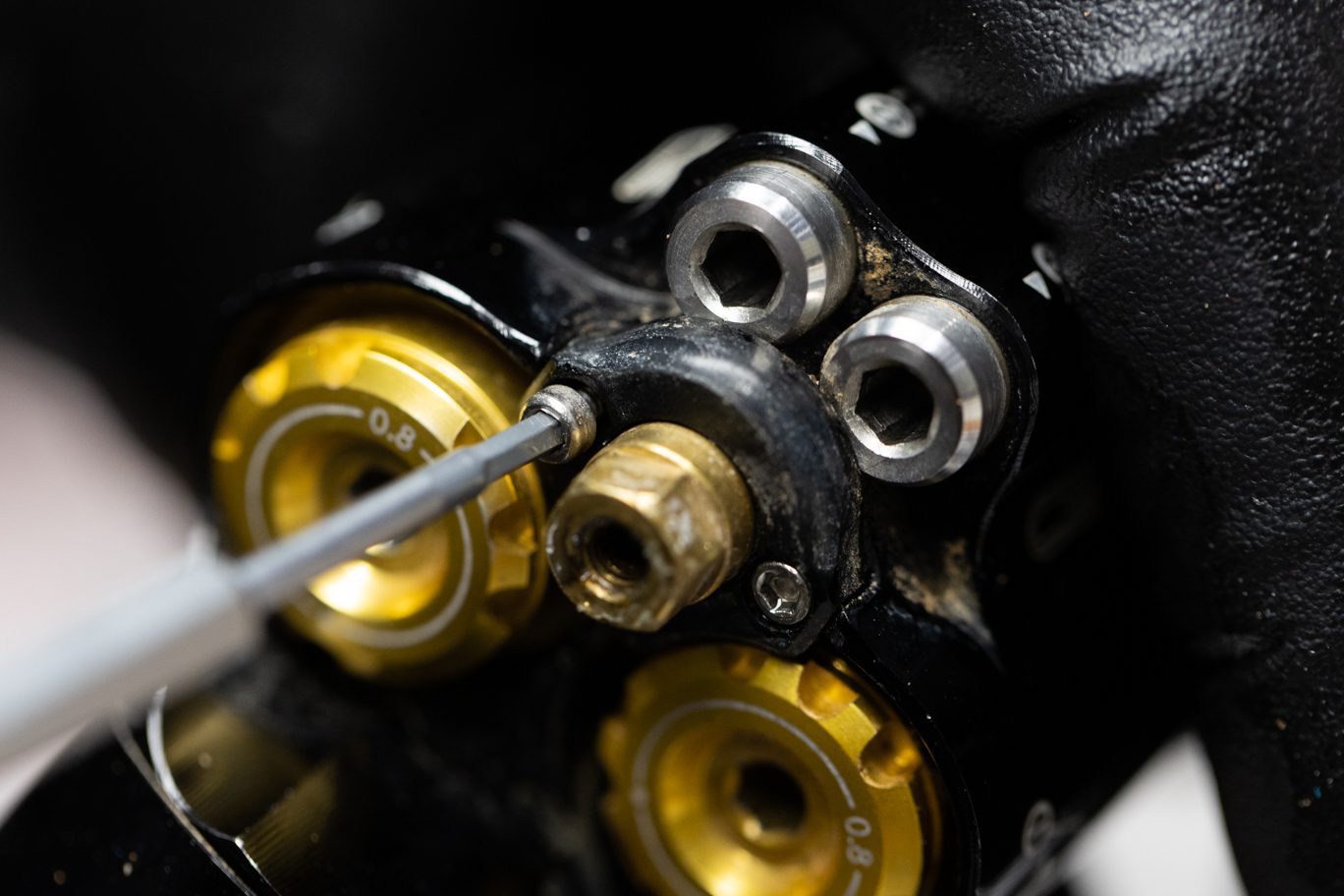
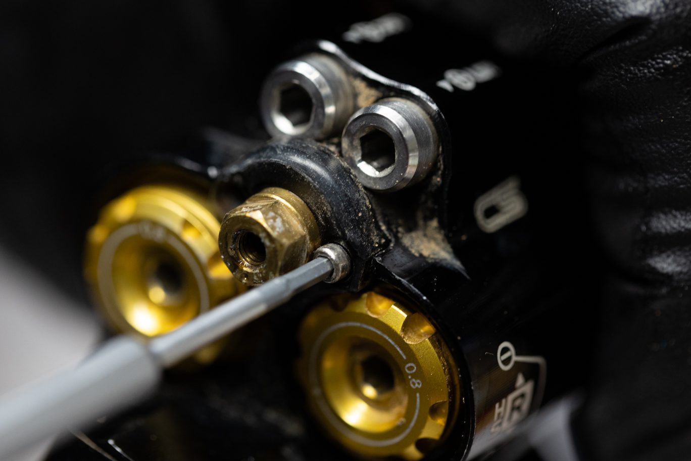
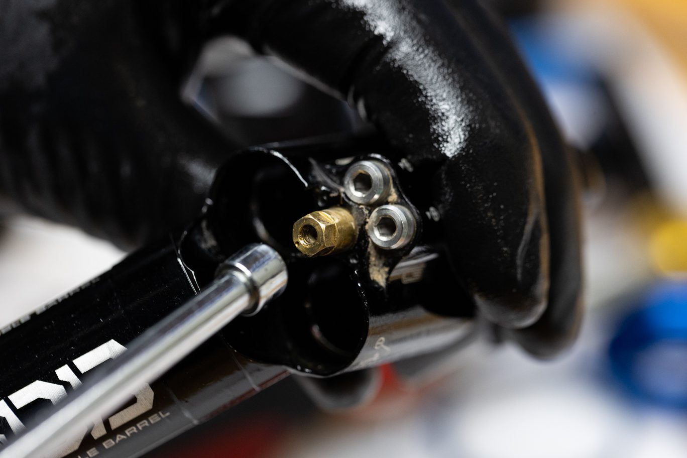
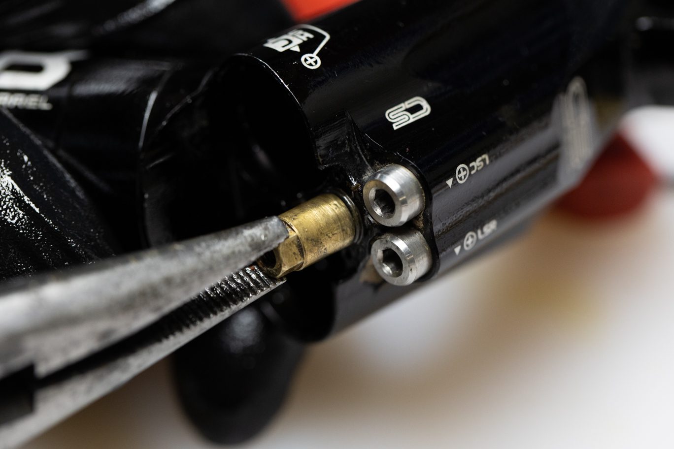
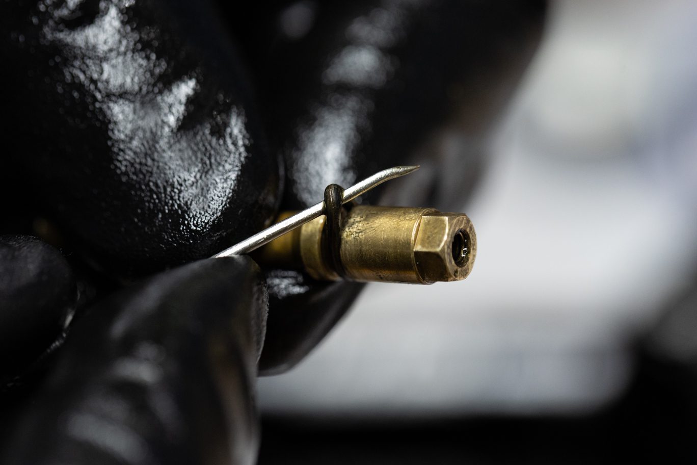
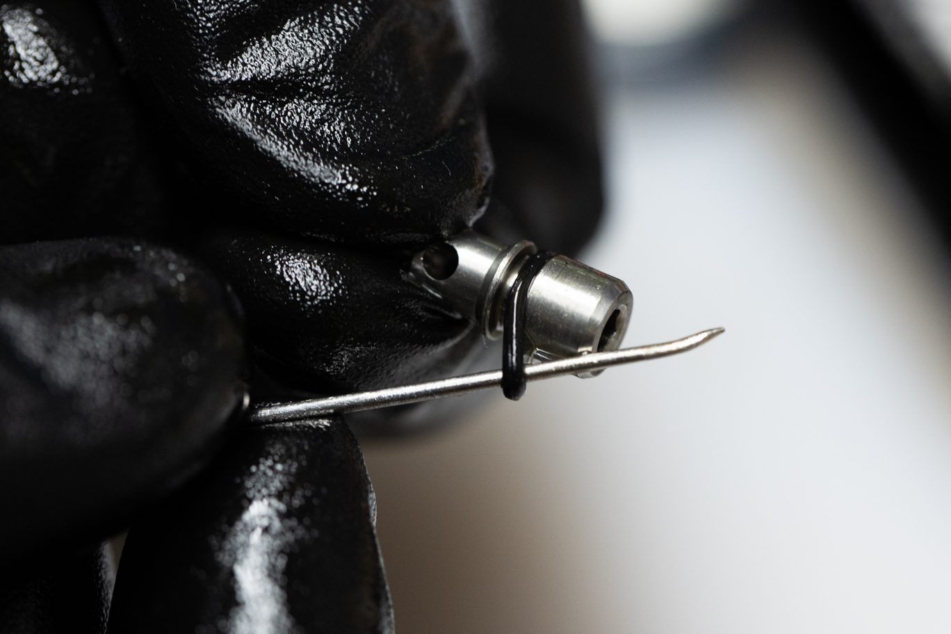
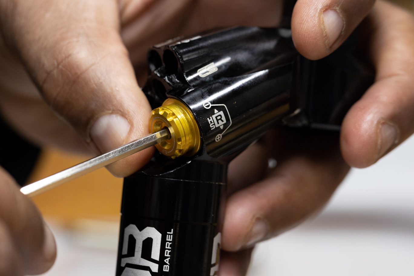
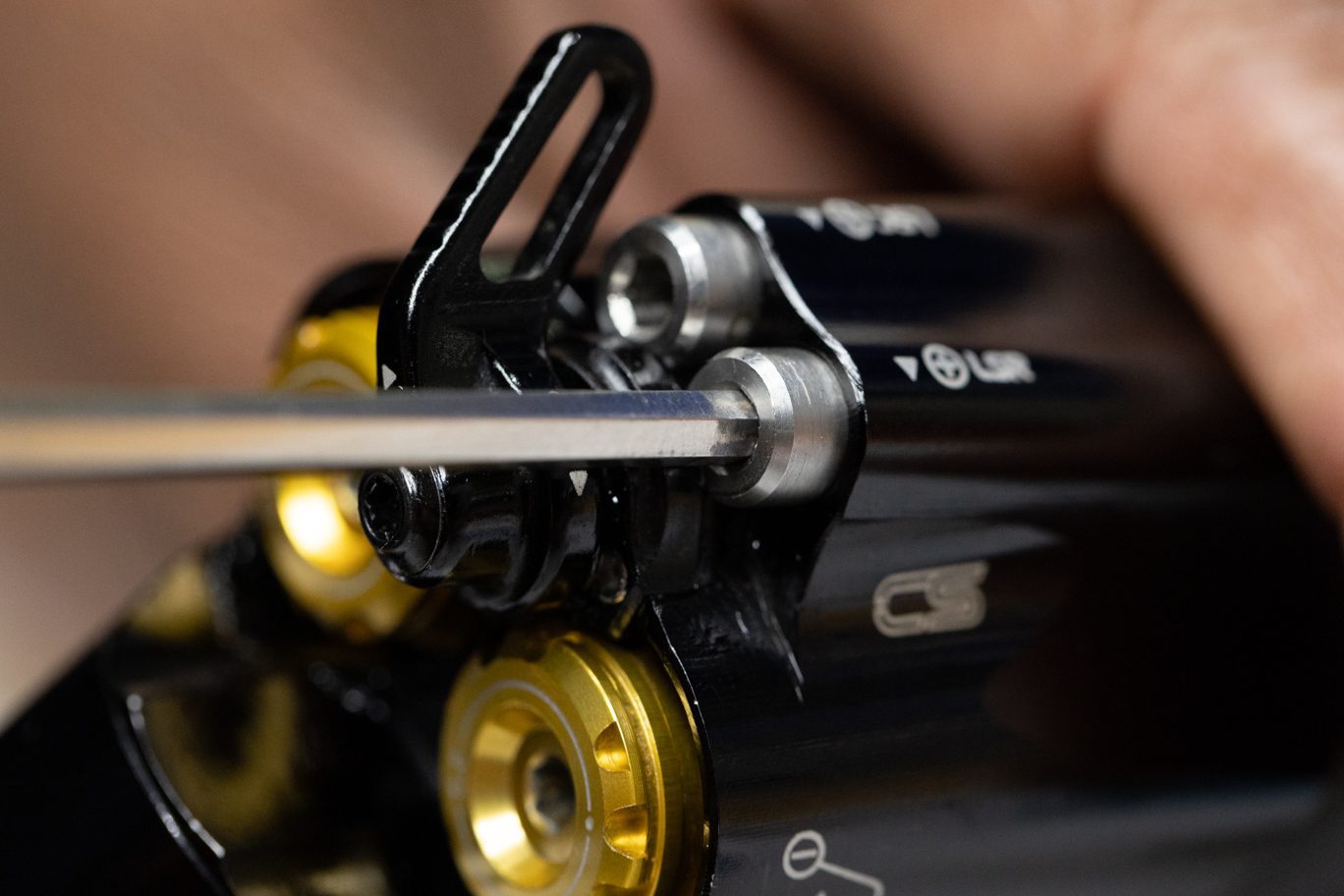
Using 3mm Allen, remove Low Speed needles. Pliers may be necessary to remove assembly once completely unthreaded. Take note of labeling on needles for reinstallation back into same circuit. Remove and clean detent balls and spring. Pinch & remove Low Speed needle o-rings.
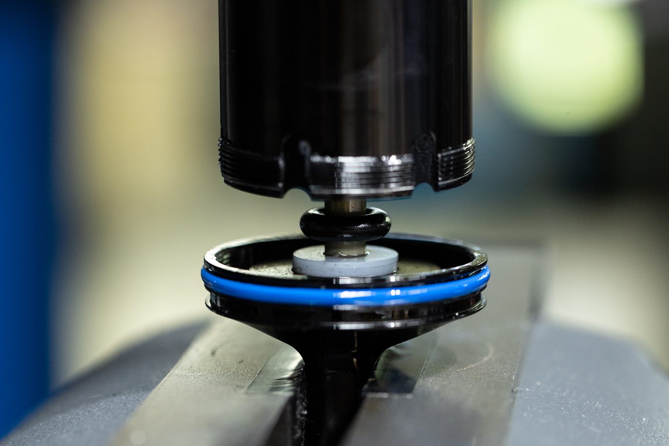
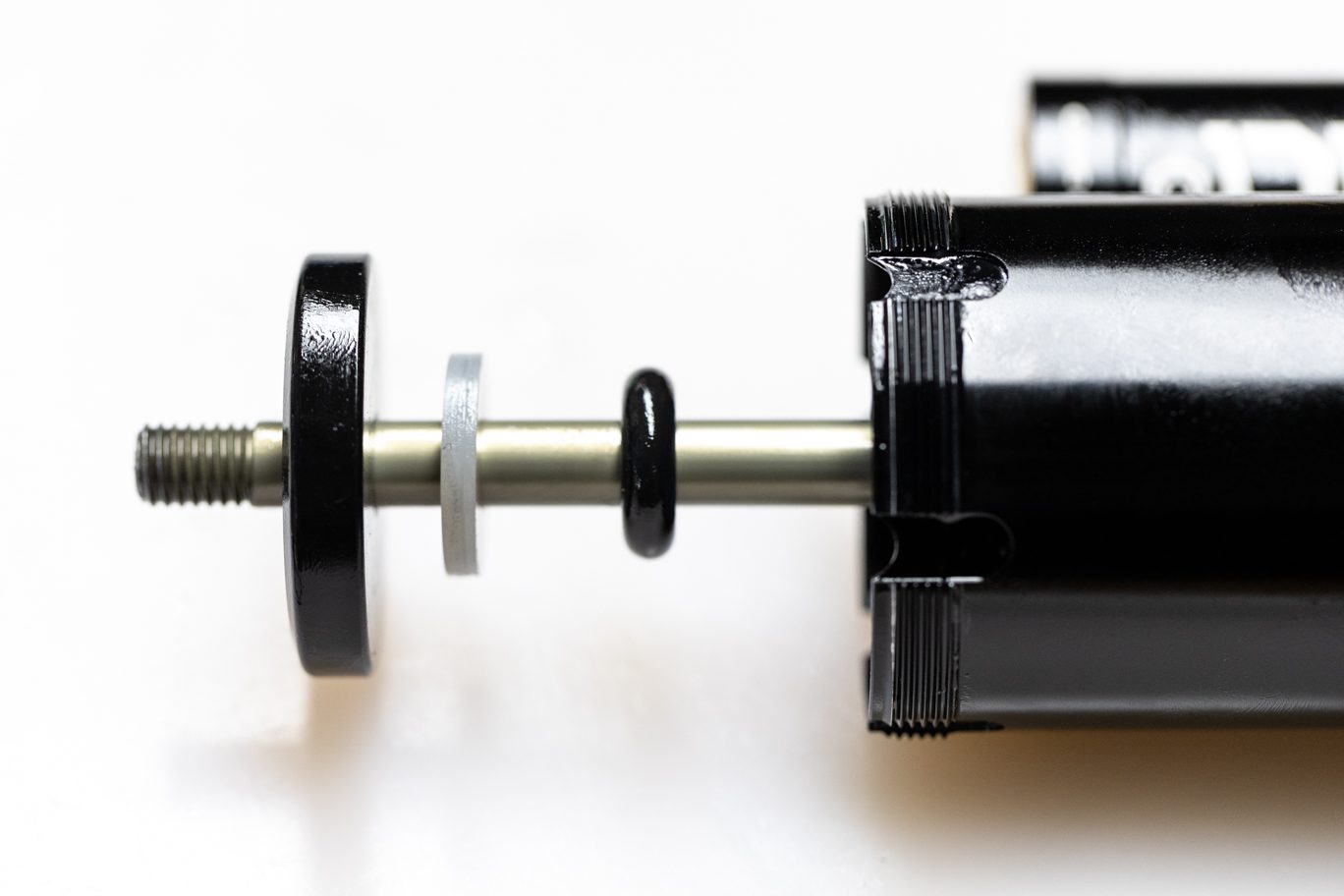
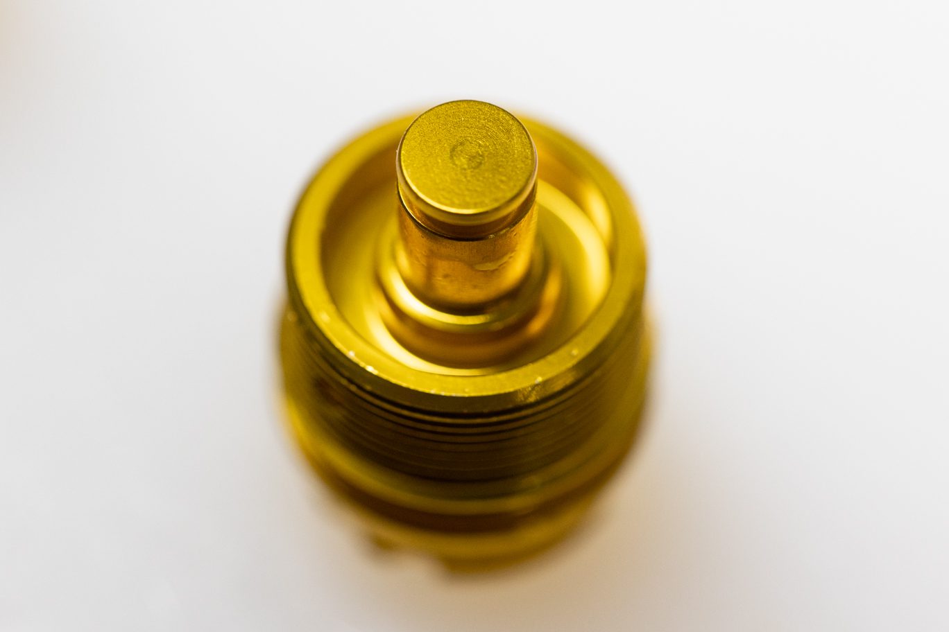
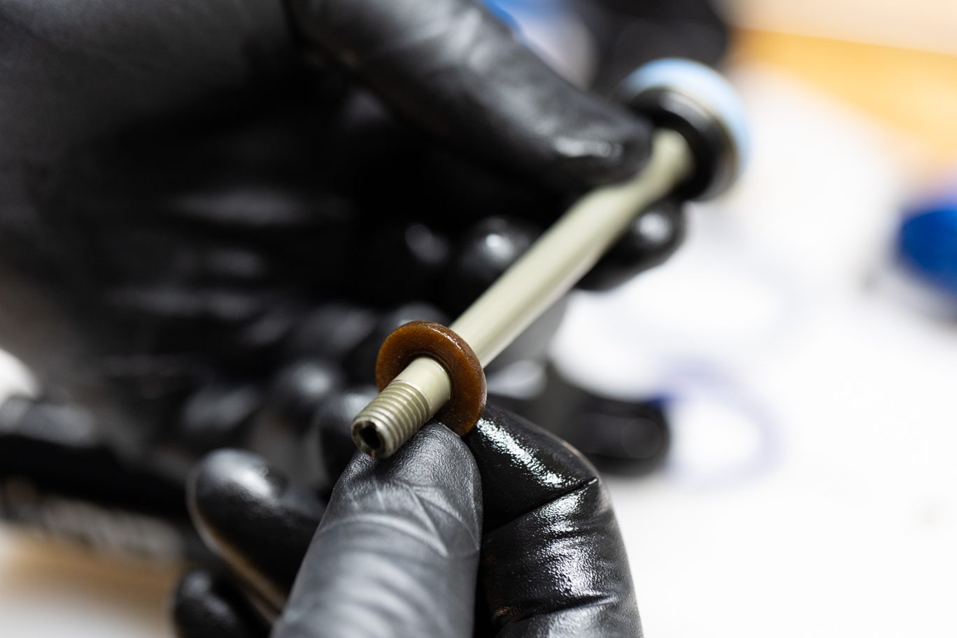
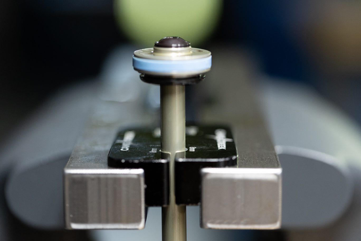
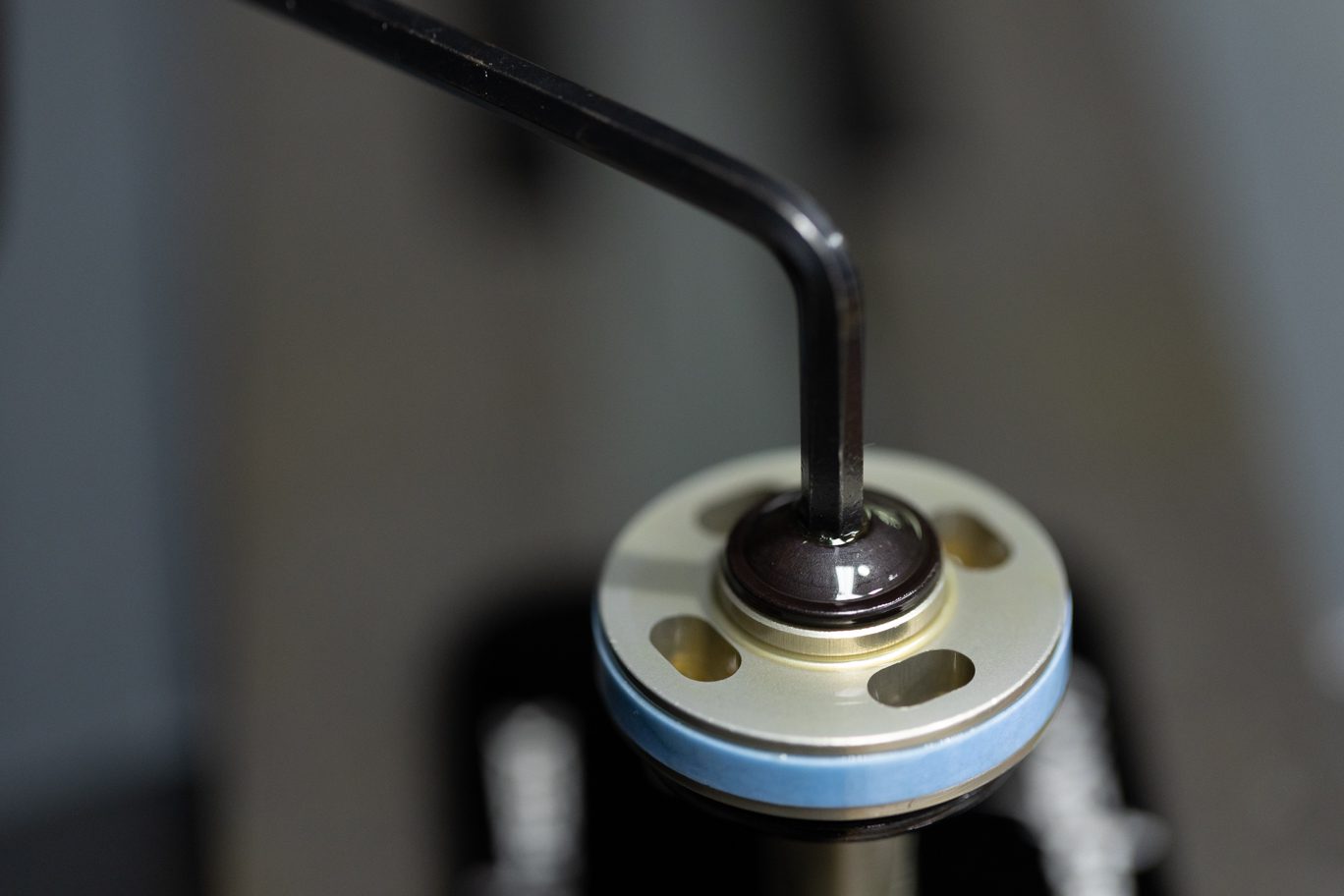
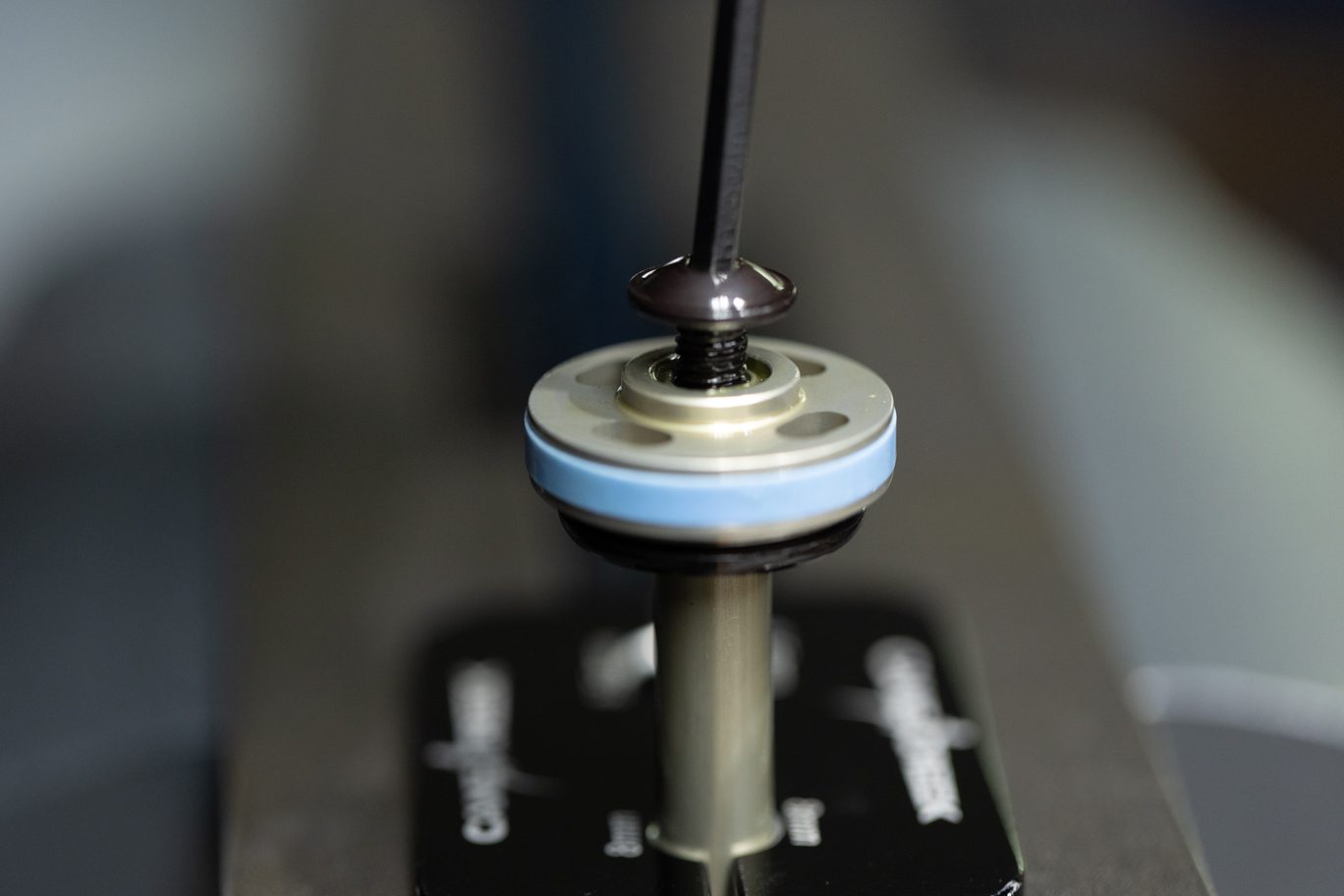
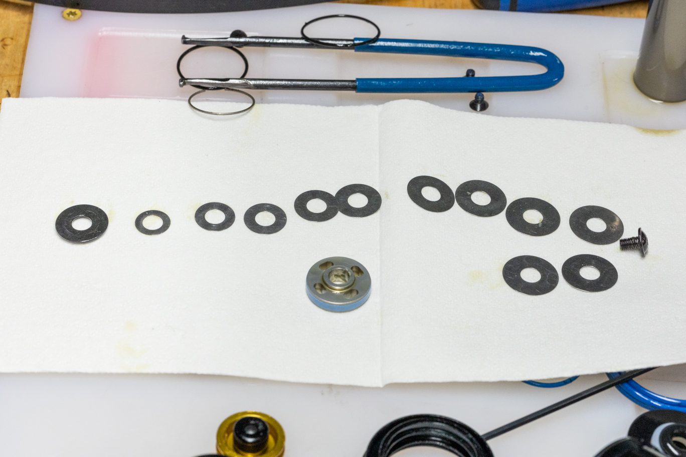
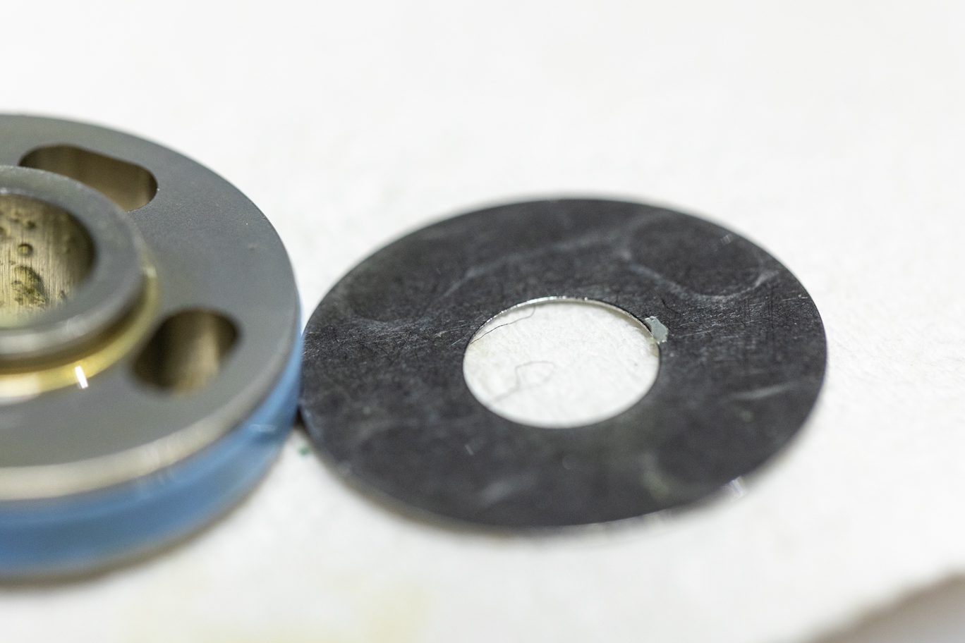
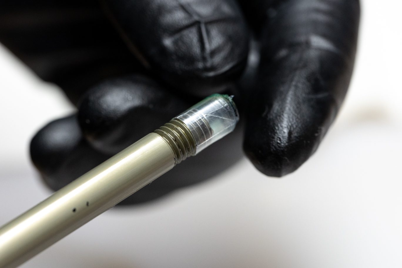
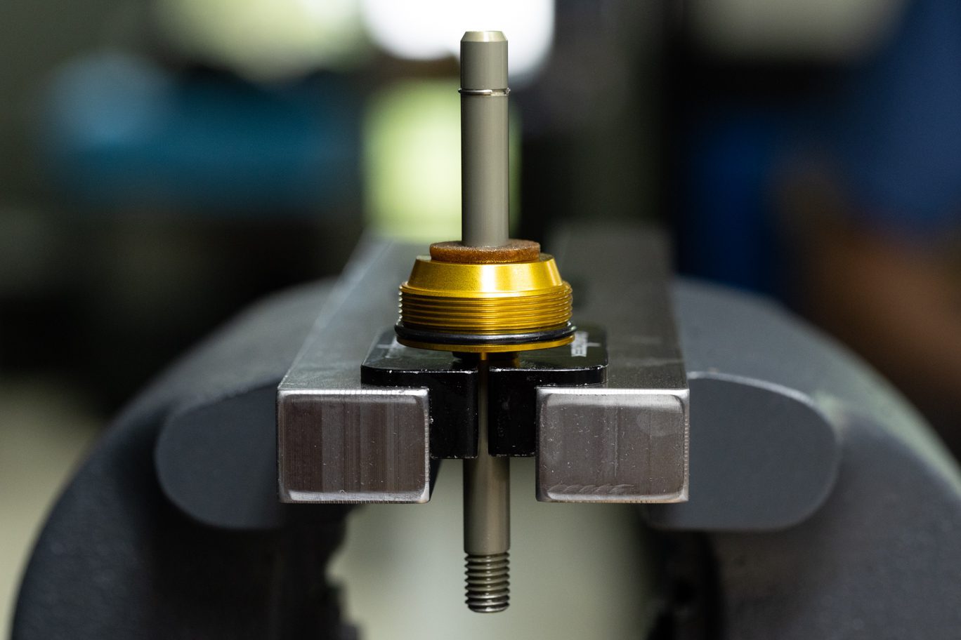
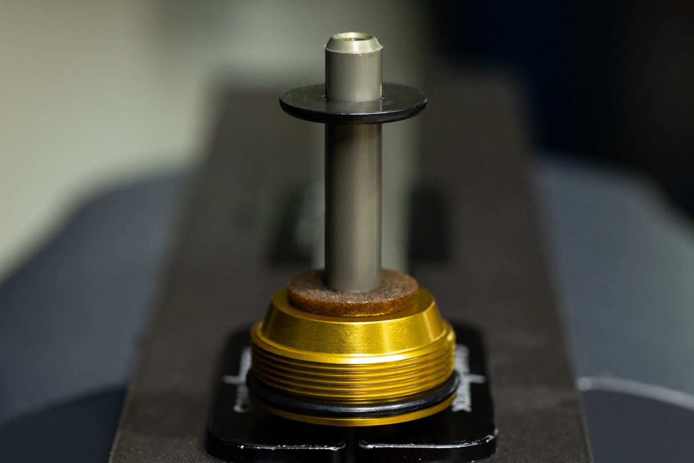
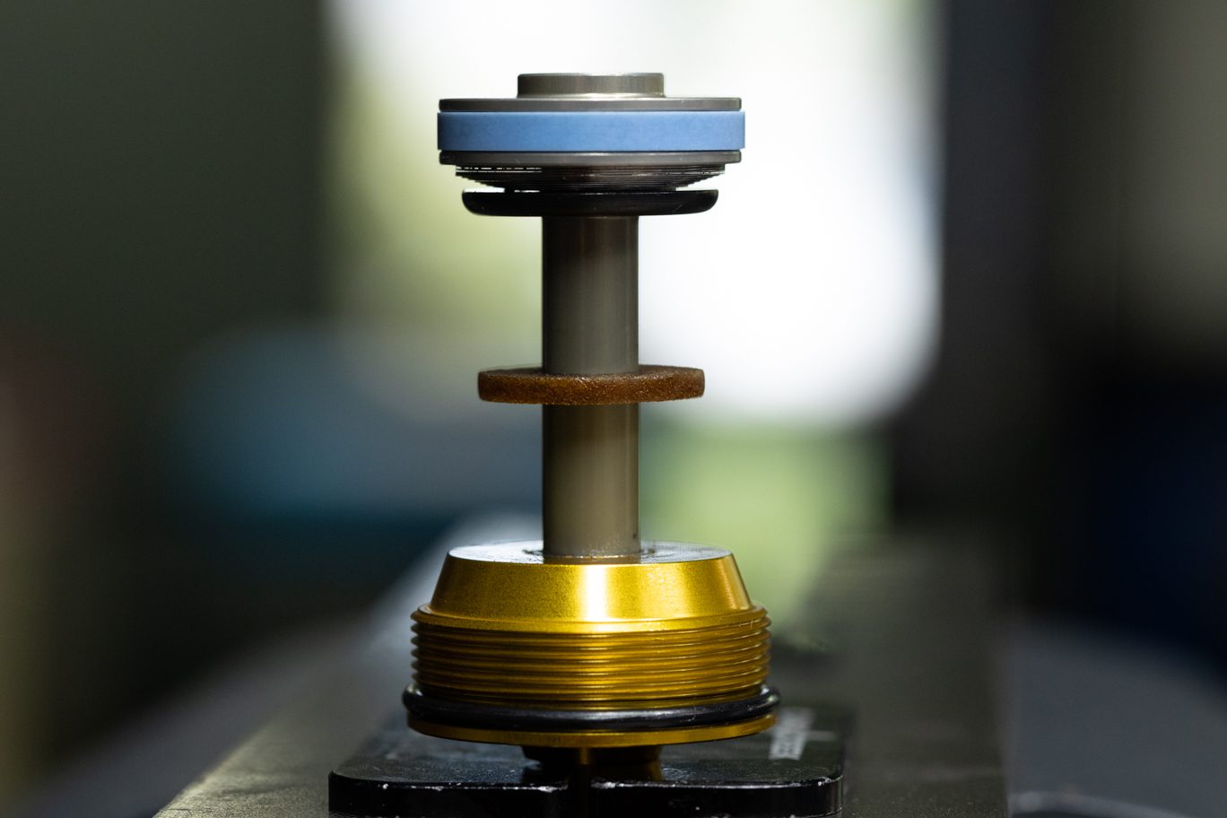
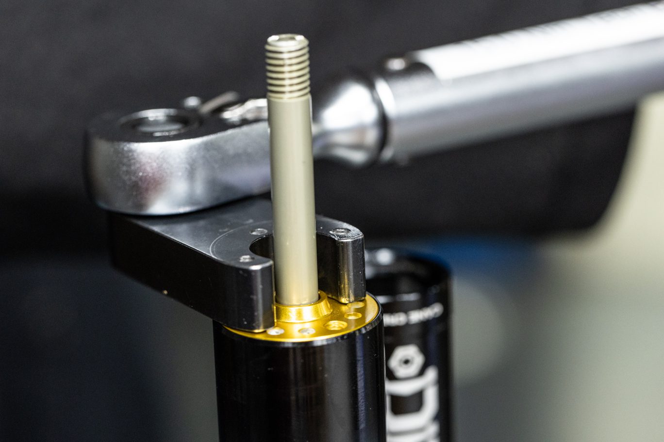
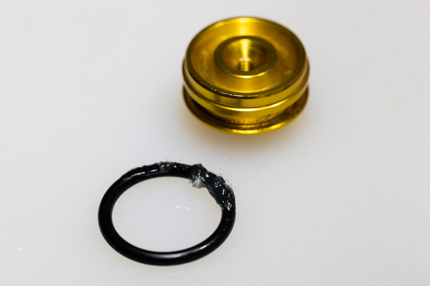
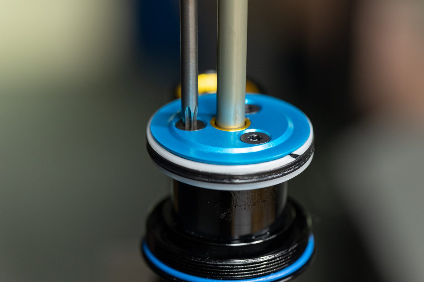
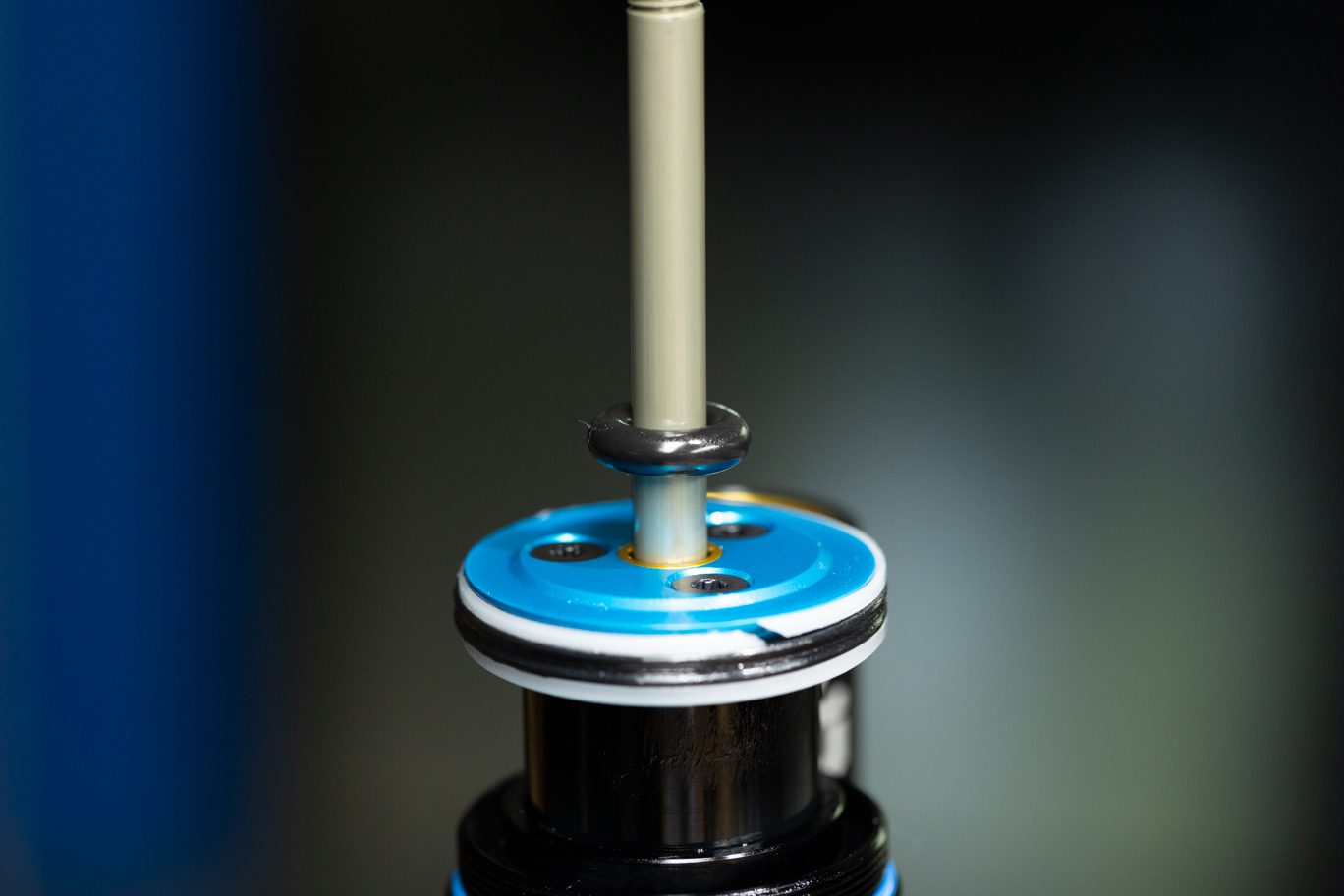
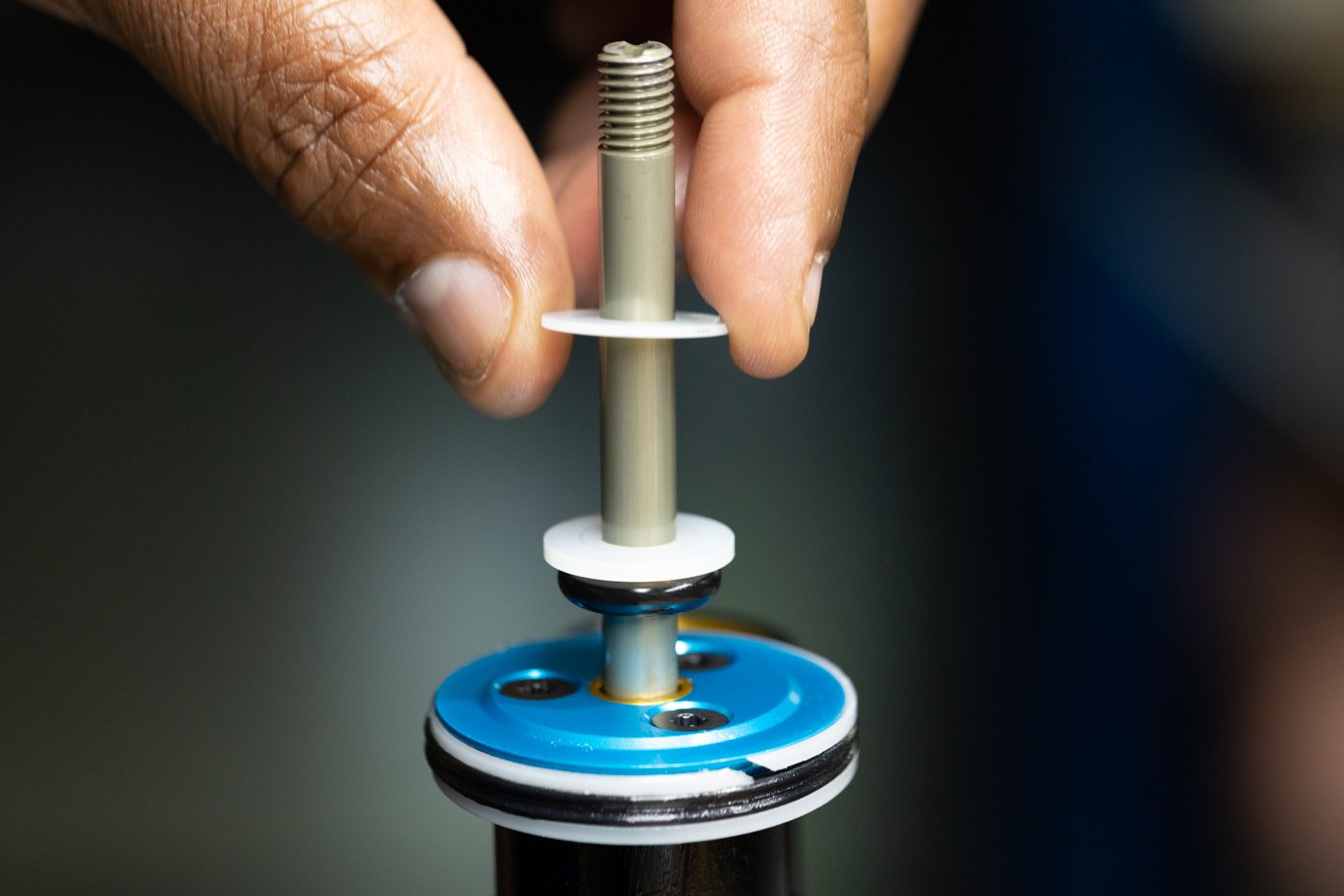
Remove and discard oil seal head and top out bumper. Inspect shaft for any damage. Replace if necessary. Clamp shaft in vise with piston up. Using 3mm Allen, remove shaft bolt. Remove piston, shim stack and stop washer. Note order of shim stack. Inspect piston port holes and check shim for wear. Flip face shim on reinstall if necessary.
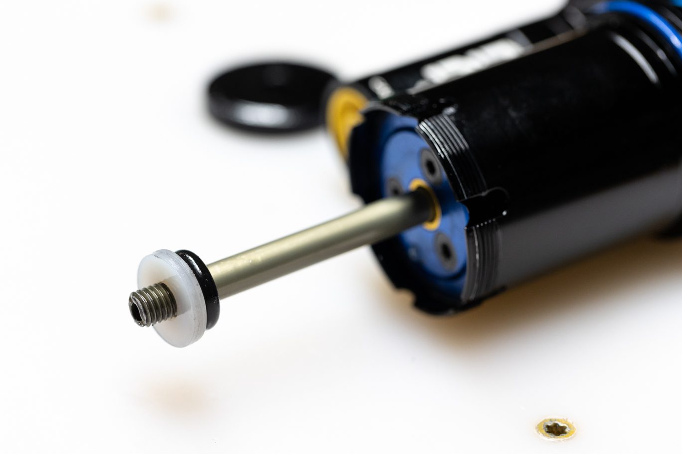
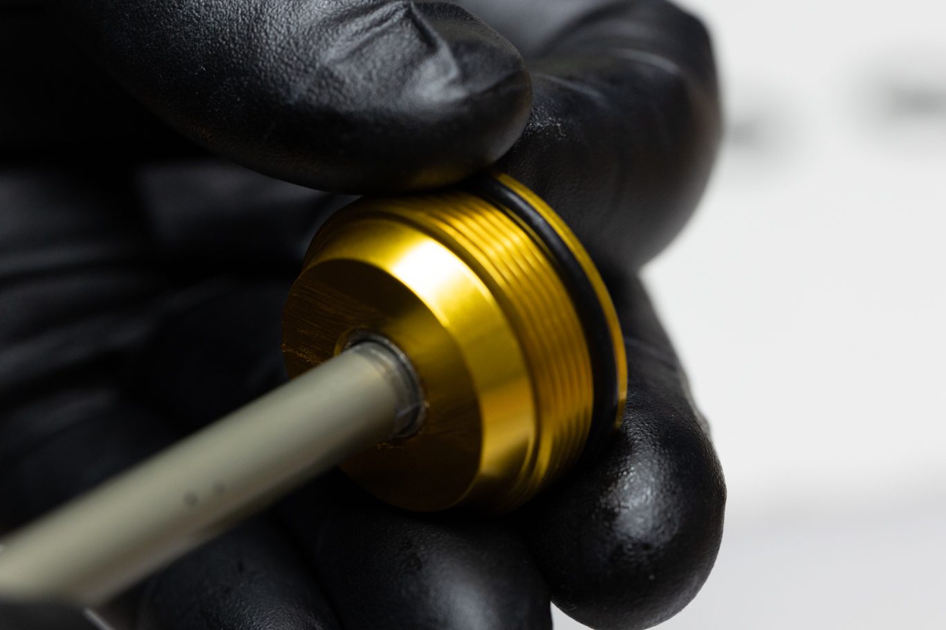
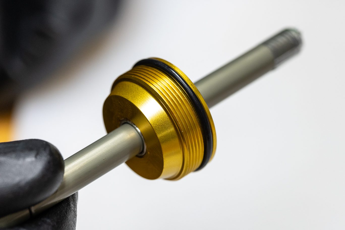
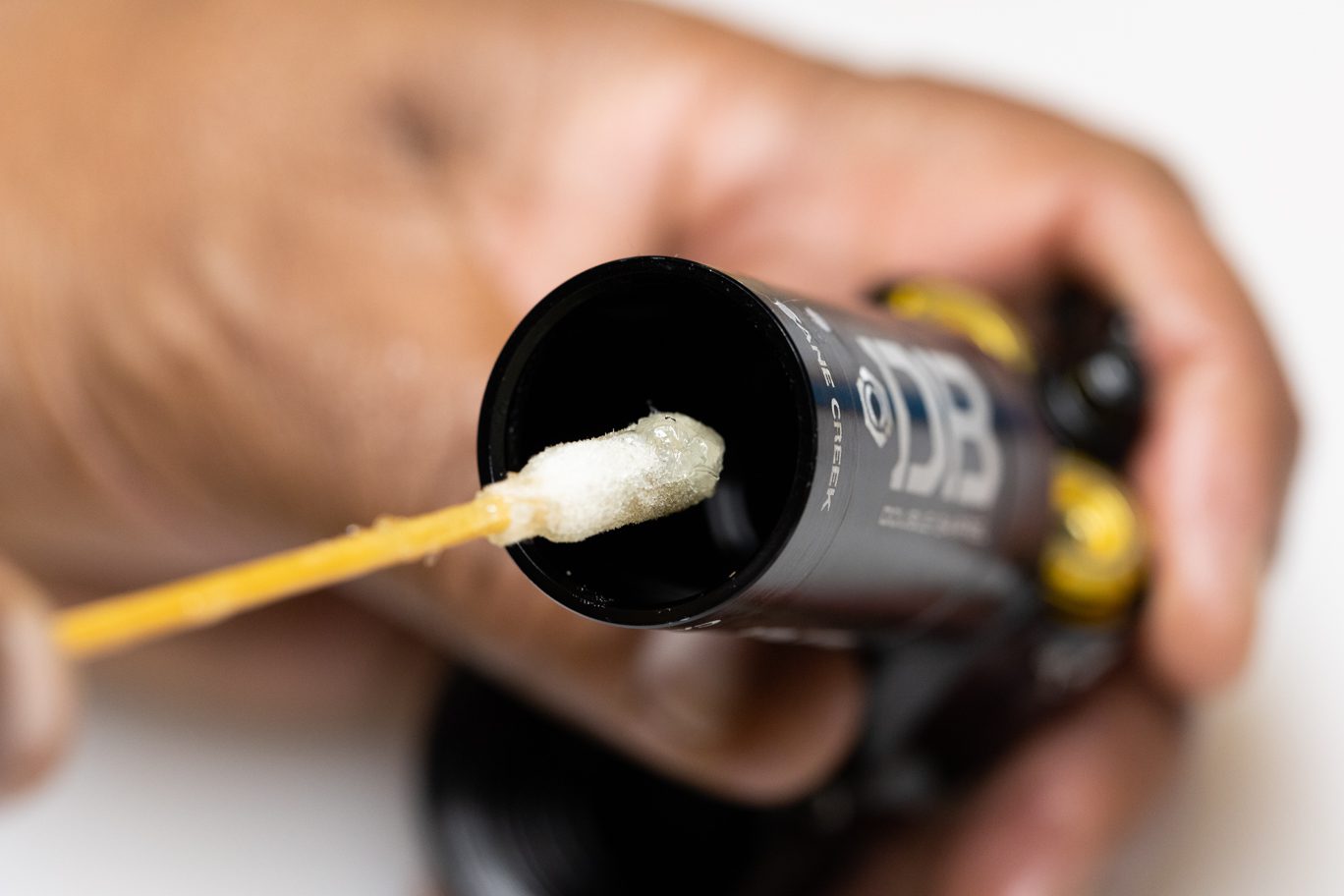
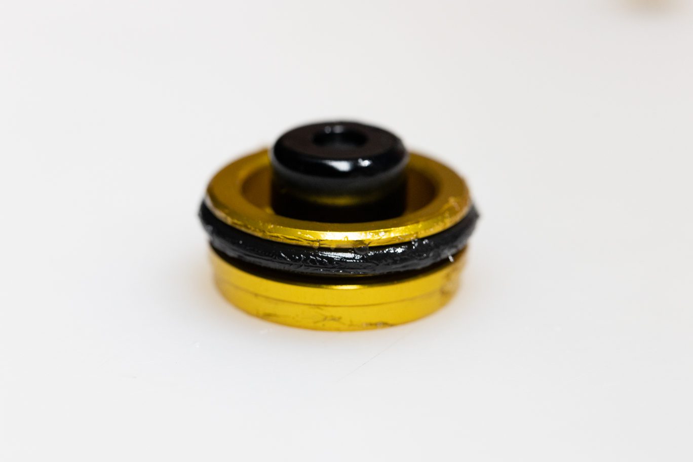
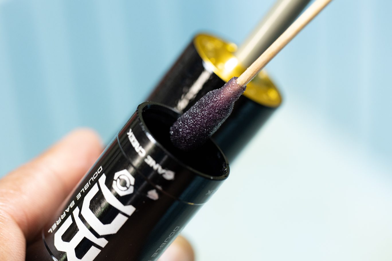
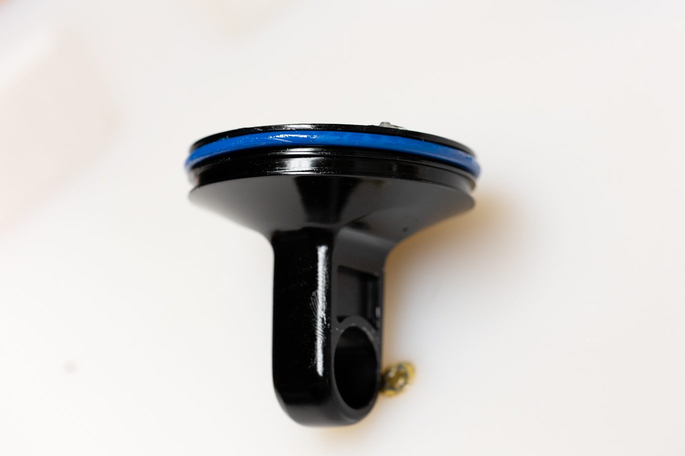
Thoroughly grease bushing and quad ring on new oil seal head (AAD0163). Lightly grease and install exterior oil seal head o-ring (.DB11108). If avaialble, slide shaft cover on shaft to cover threads only. Trim shaft cover to length if necessary. If cover not available, you can use tape to cover threads or simply take care installing seal head. Install oil seal head and new top out bumper (AAD1090), noting correct orientation.
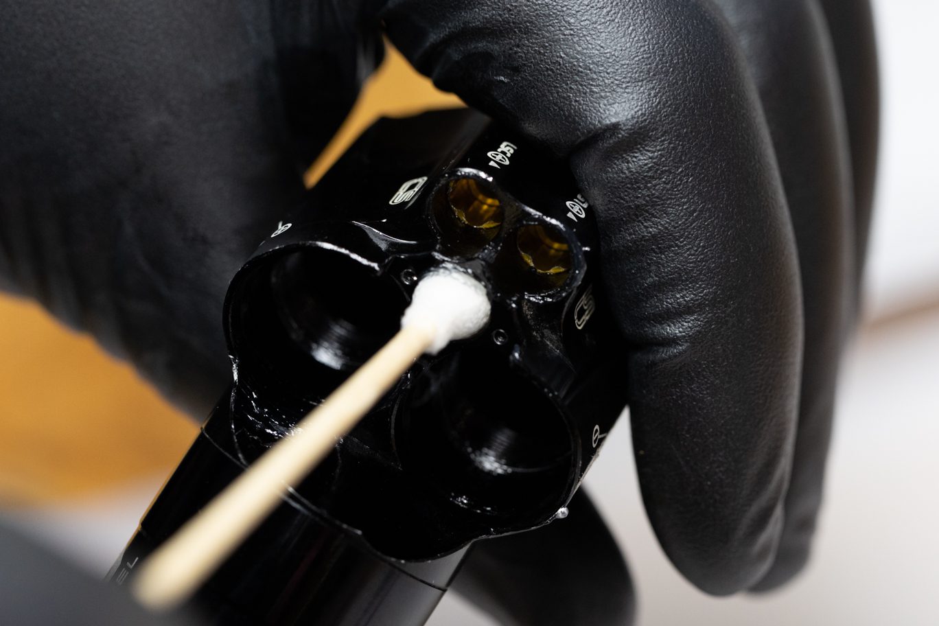
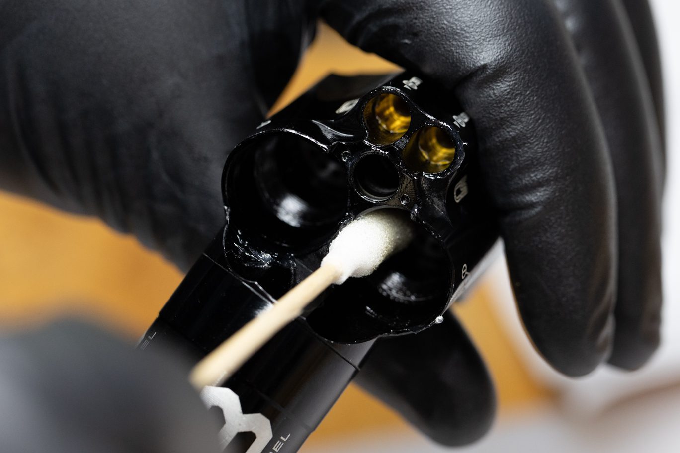
Lightly grease the walls of the spool valve and adjuster housing on valve body. Lightly grease and install high speed adjuster outside o-ring (AAD0032). Install high speed adjuster poppet o-ring (.DB11101). Install spring and poppet on high speed adjuster.
Replicate the original set up from disassembly. Rebound adjuster (0.8 with port) and spring (red, 30wt weight) and Compression adjuster (will vary from 0.0 without port, to 0.8, 1.0 or 1.2 with port) and spring (yellow, 10wt or standard 20wt). Spring color may have worn off.
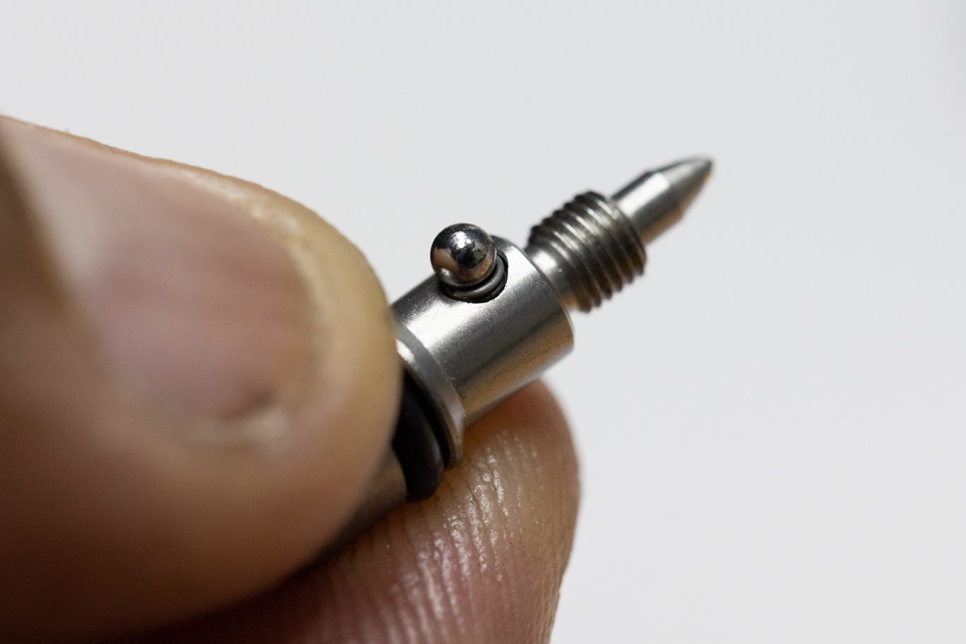
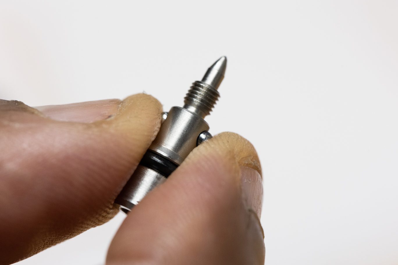
Lightly grease and install low speed needle o-rings (.DB11102). Using grease, install detent ball, spring and second detent ball. Using 3mm Allen, install low speed needles into valve body. Be sure to match needle to original circuit. Thread needles below cover plate surface. Test for detent clicks at this time.
Lightly grease and install spool valve o-ring (.DB11102). Lightly grease spool valve opening on cover plate. Using grease, install detent ball, spring and second detent ball.
Install spool valve. Repeat removal process of threading spool valve all the way closed (clockwise) then opening (counterclockwise) 1/2 turn and onto indicator dot at 6:00.
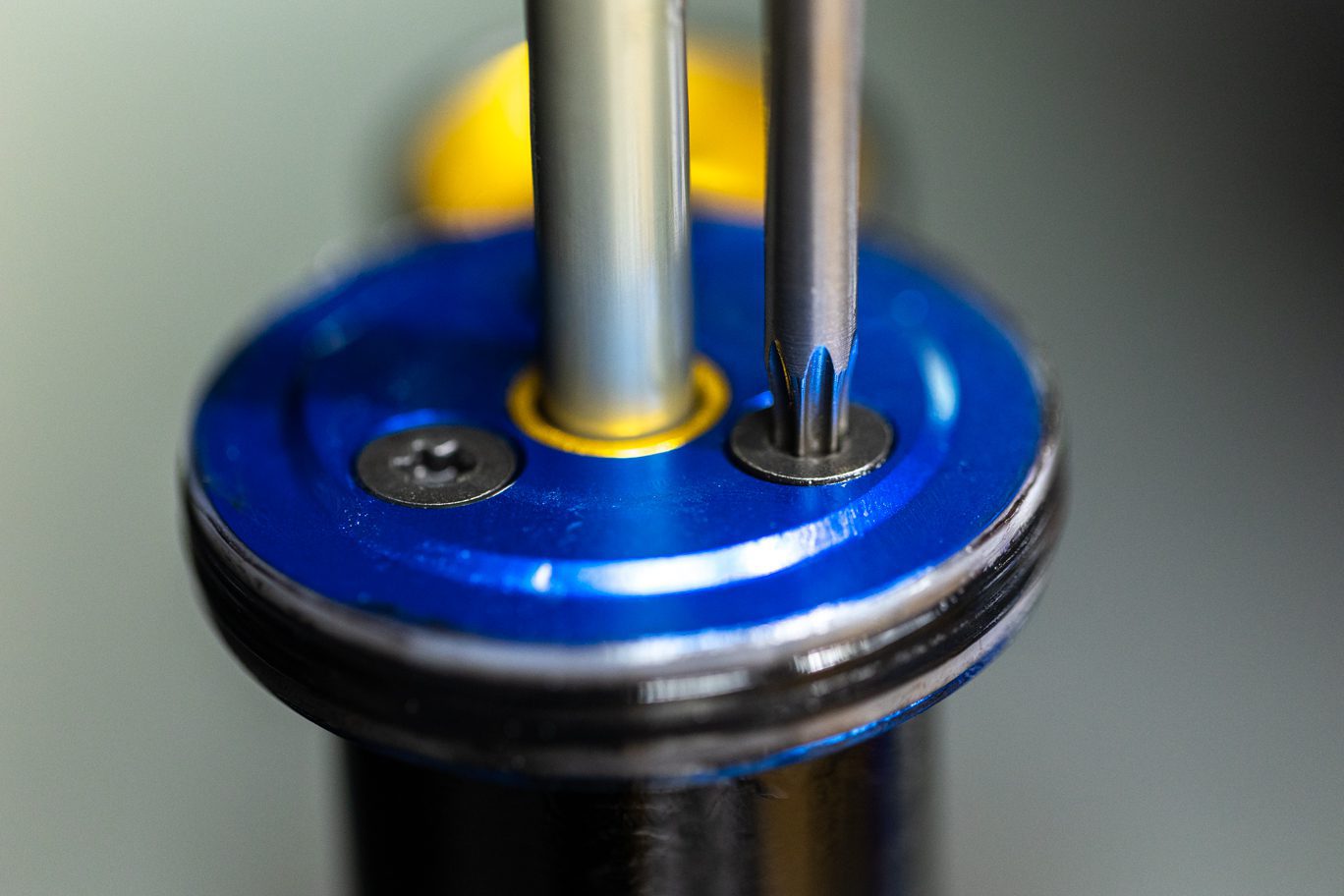
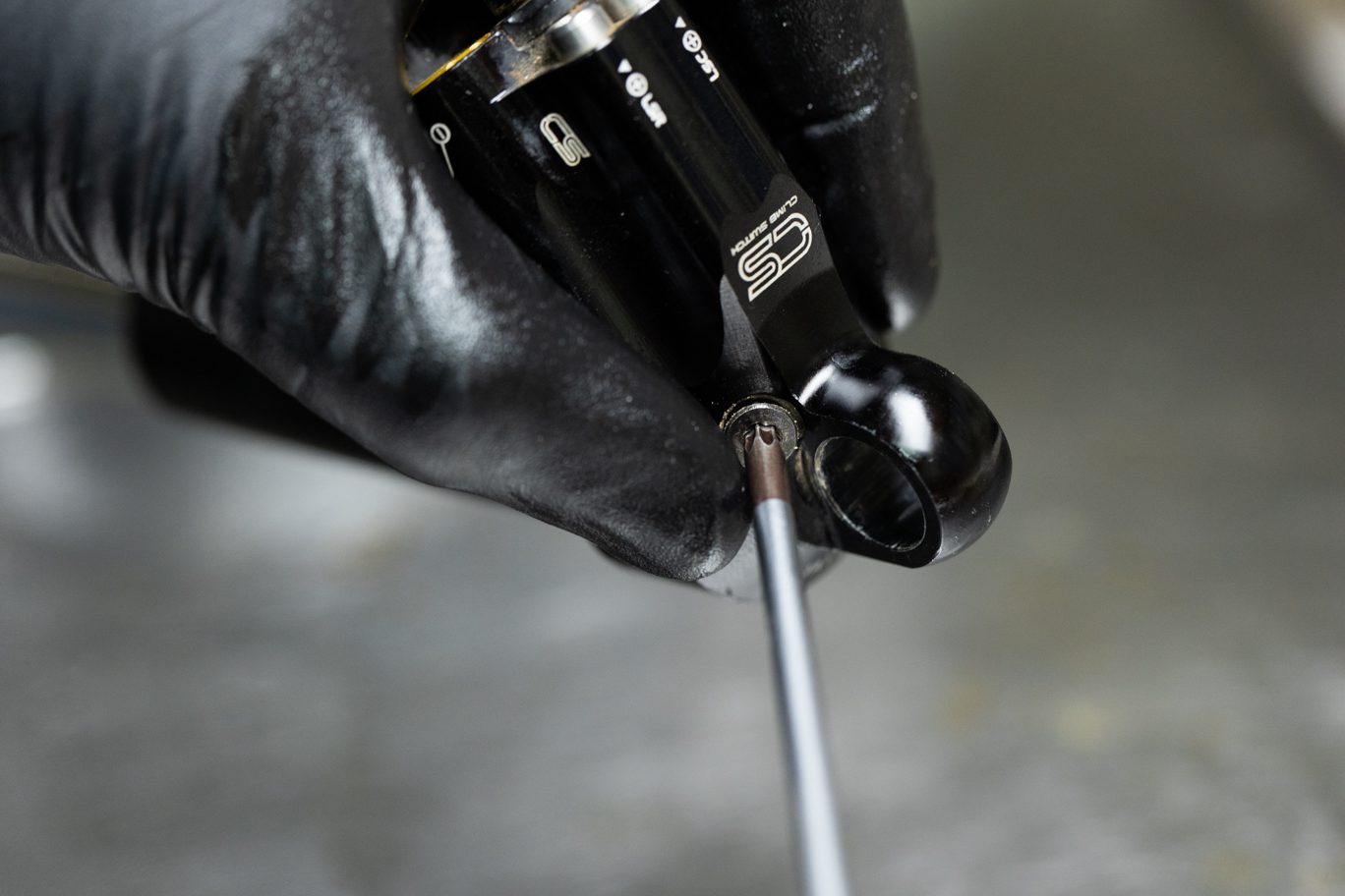
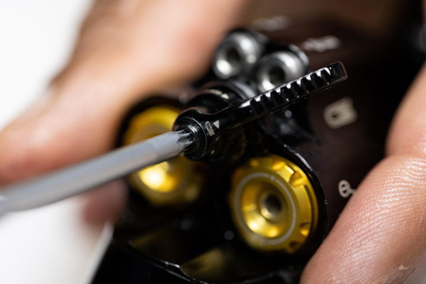
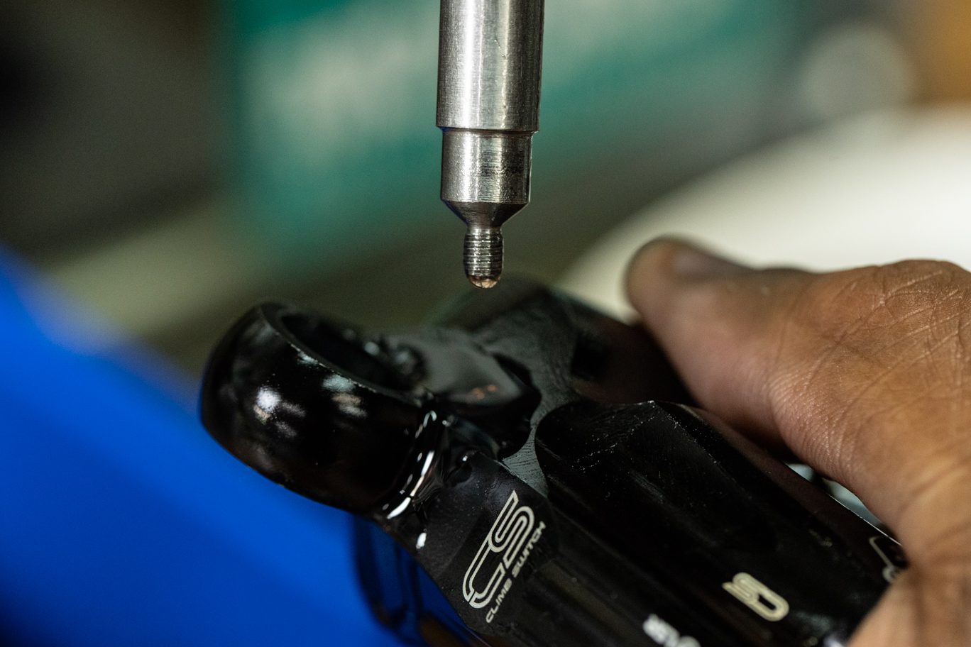
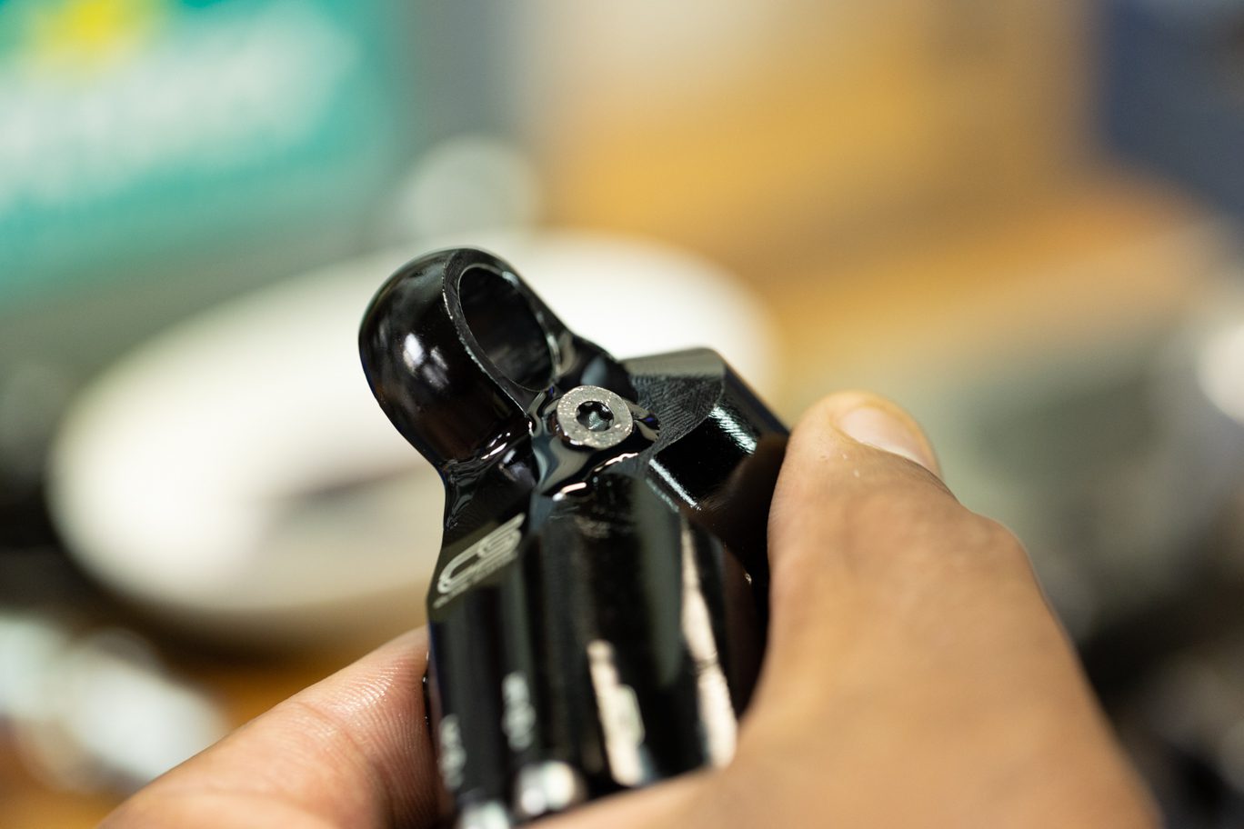
Apply blue (243) Loctite to internal threads on spool valve. Install Climb Switch with lever pointing towards the Rebound adjusters (in the climb switch “on” position). Install Climb Switch screw and torque to 1.2 Nm using a T10 wrench. Back out both low and high speed adjusters until gently touching the cover plate.
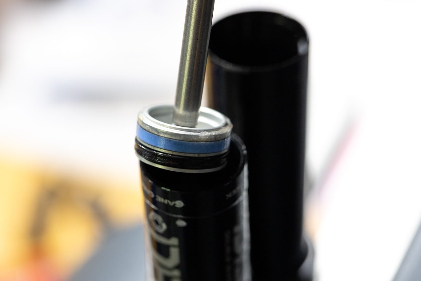
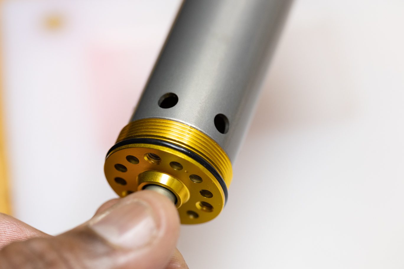
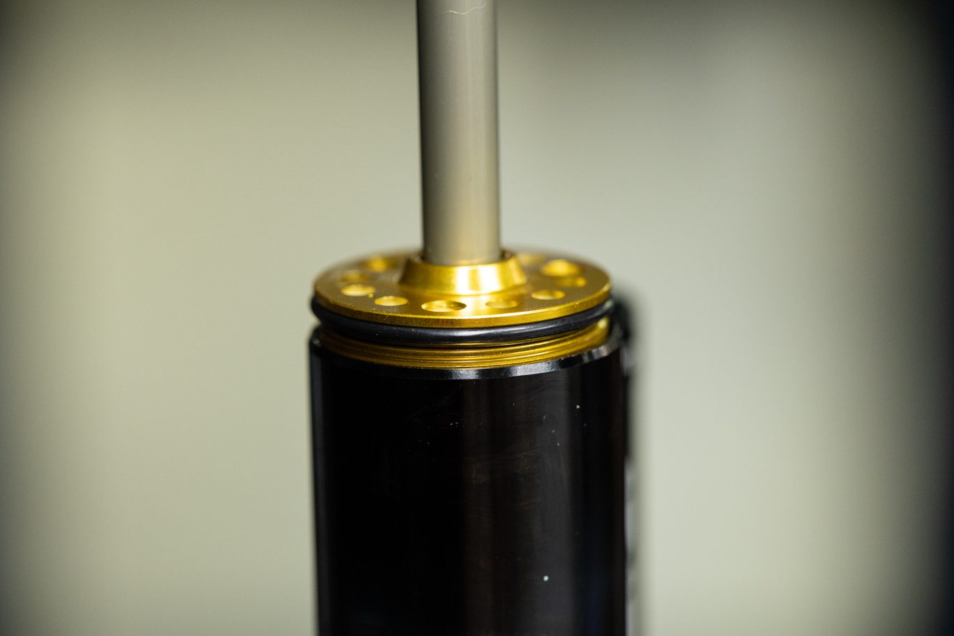
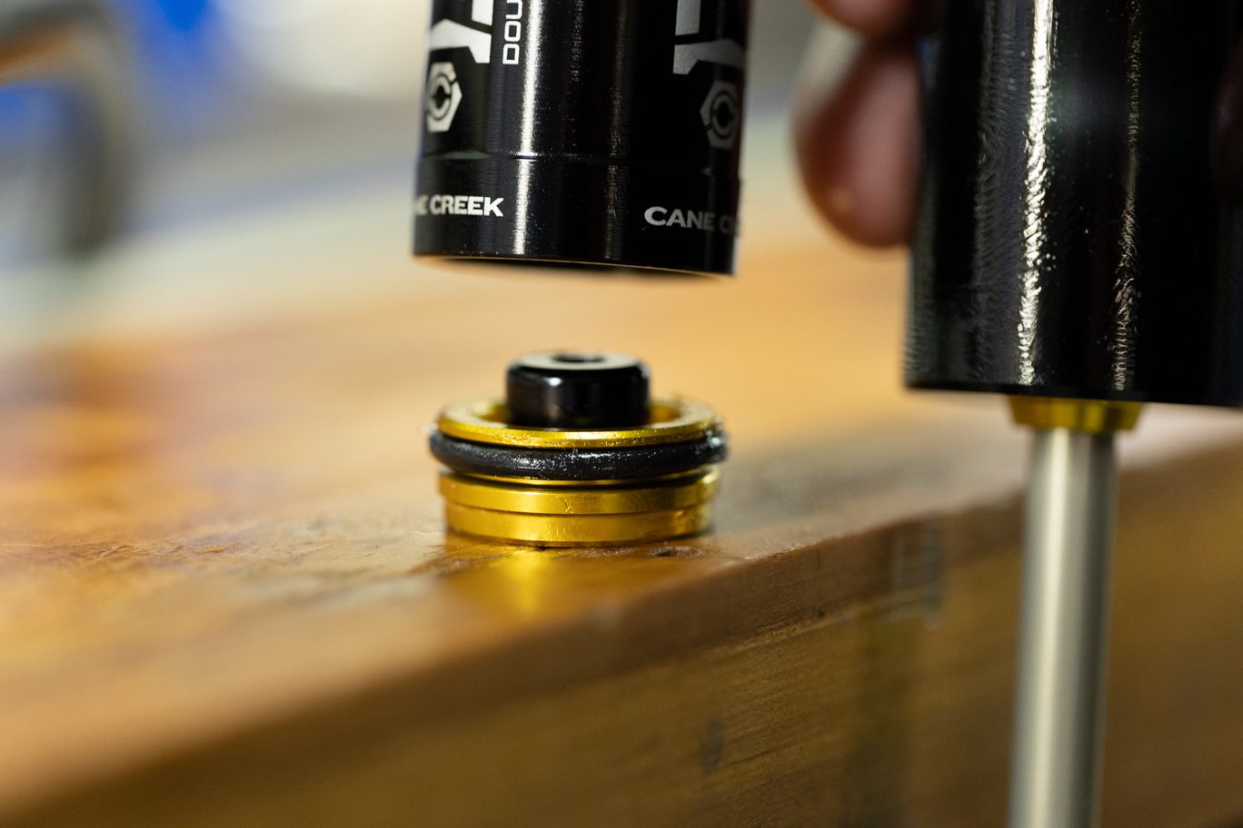
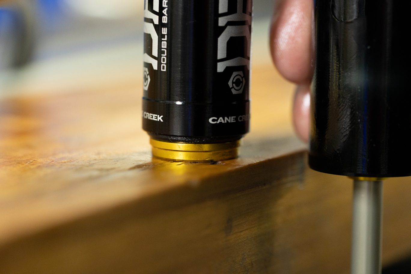
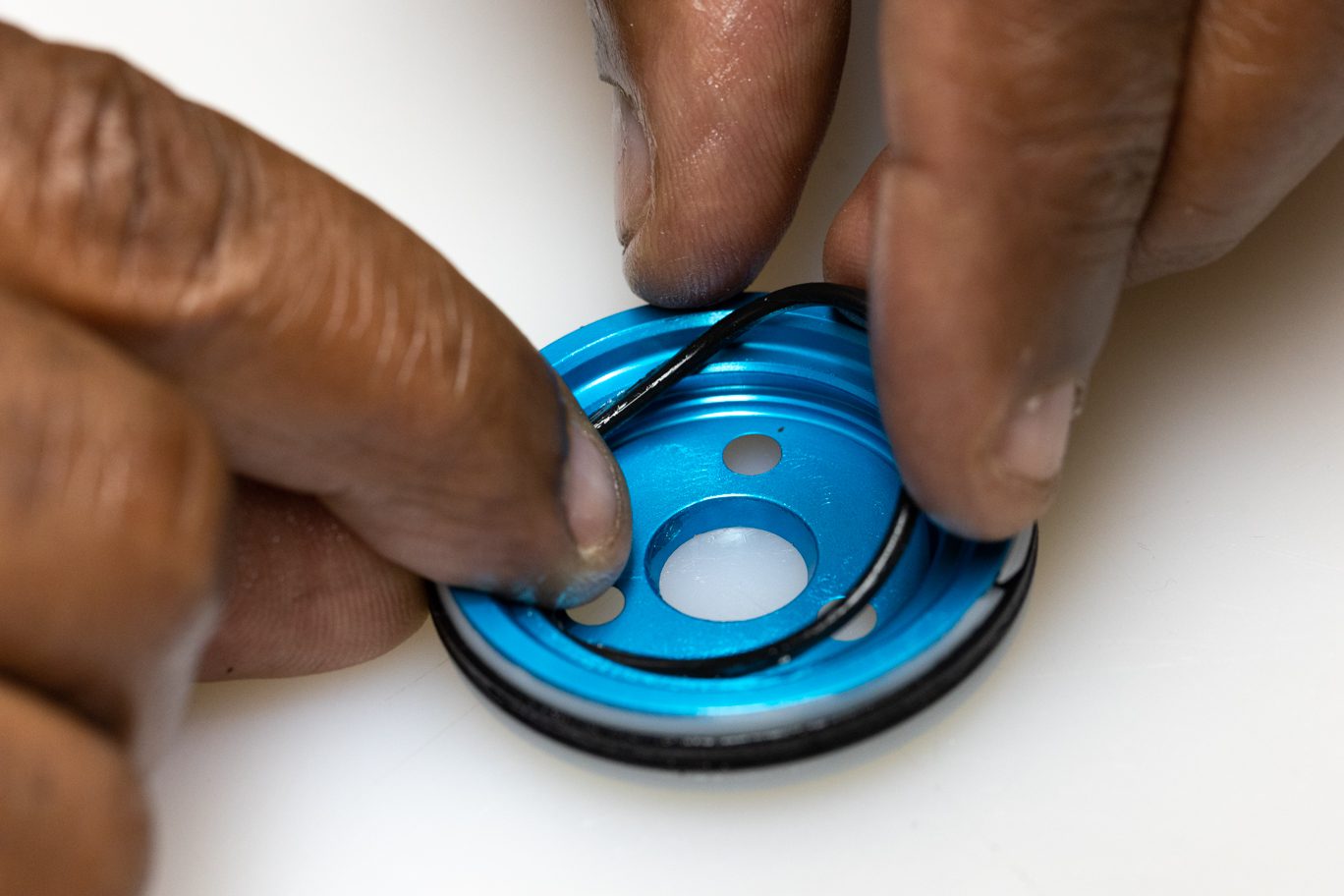
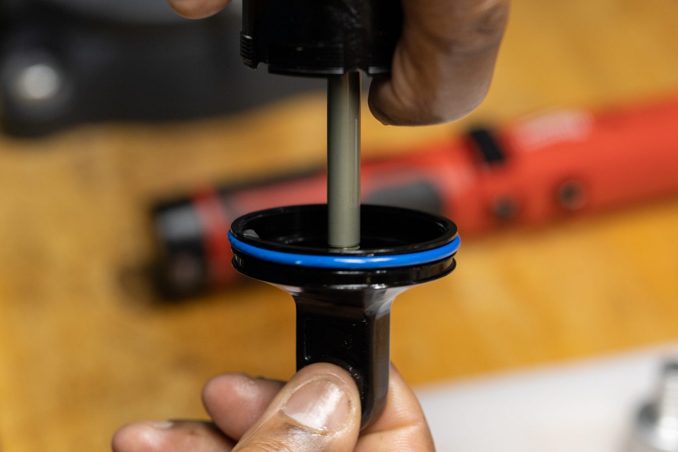
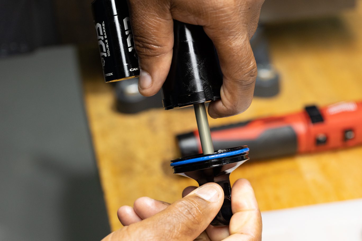
Install sag o-ring (AAD0837). Coat air piston with shock oil and insert shaft assembly into inner damper tube. Note location of holes on seal head end. Install inner damper tube/shaft assembly into outer damper tube. Thread oil seal head into outer damper tube and torque to 15 Nm using Oil Seal Head wrench.
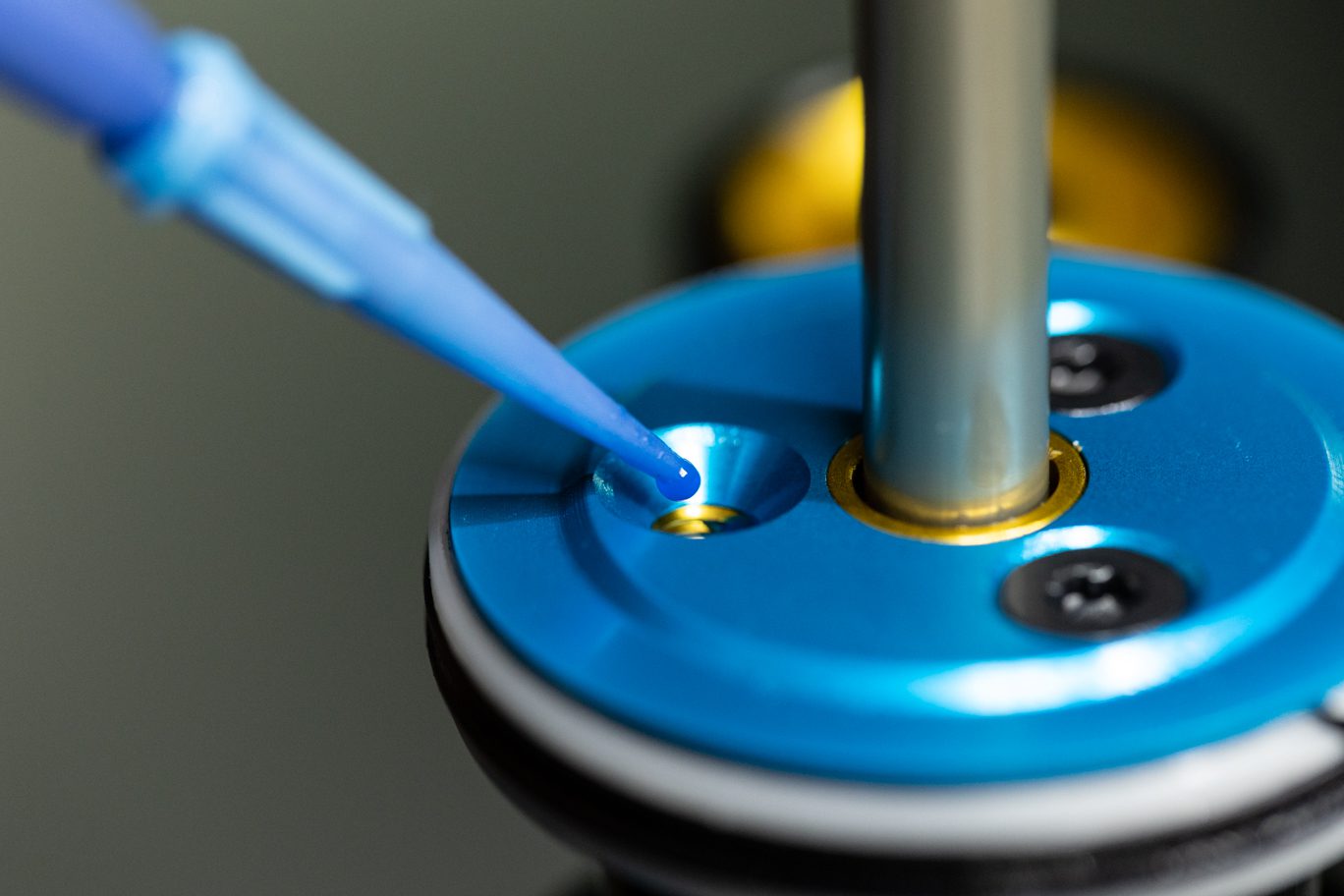
Do not use tool in holes with threads to avoid damaging threads.
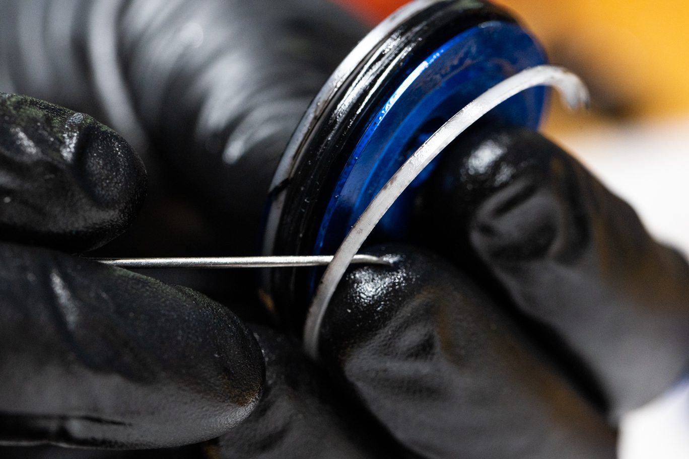
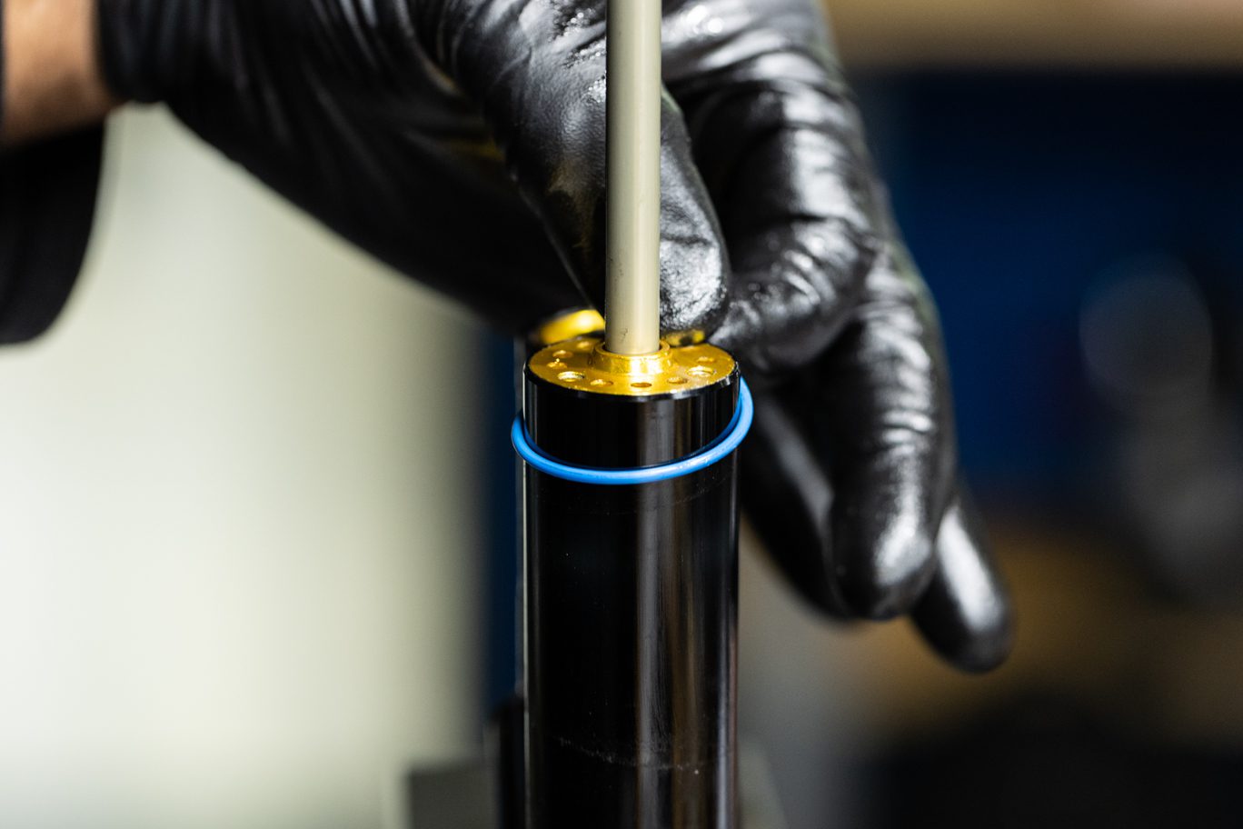
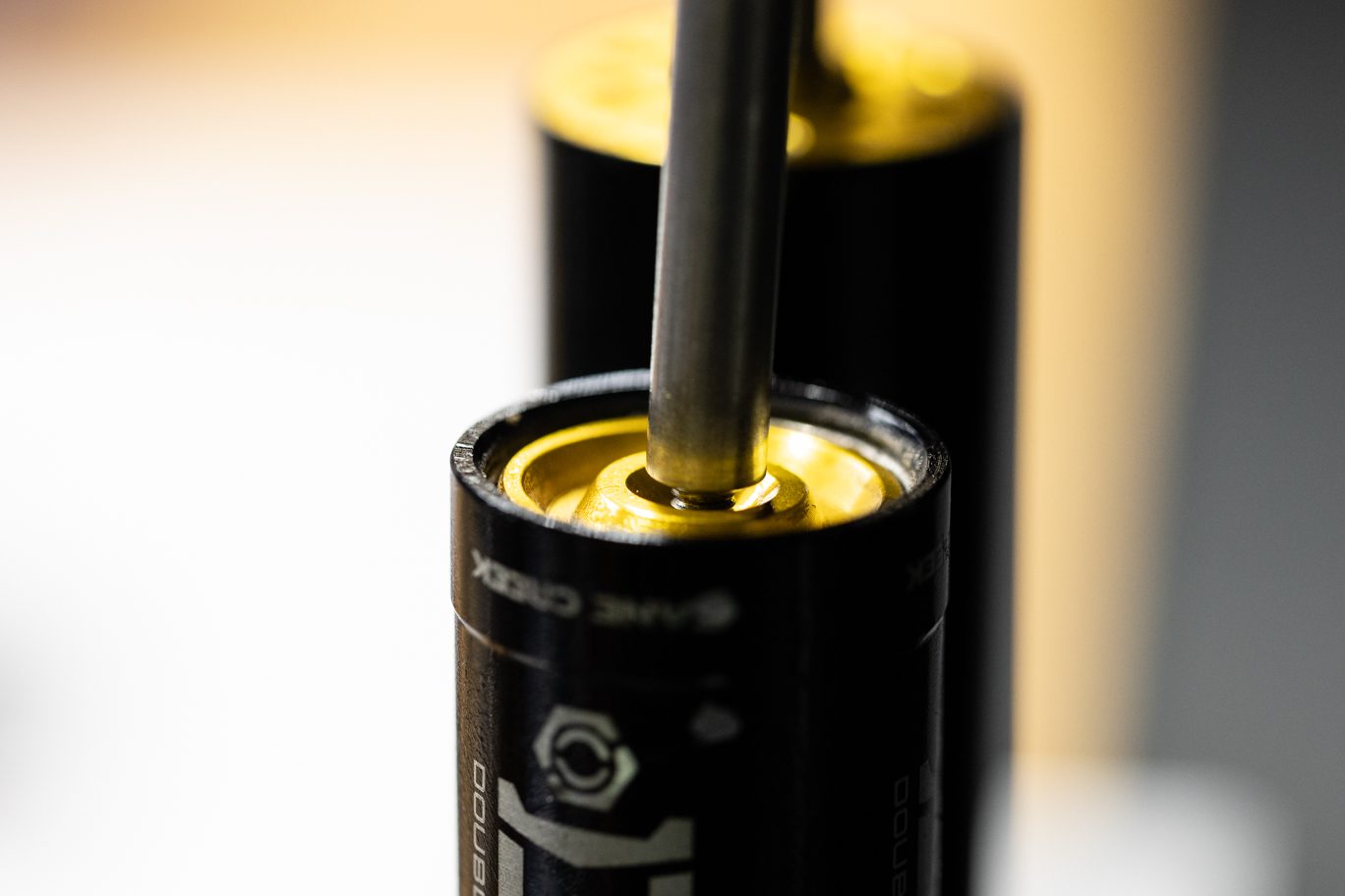
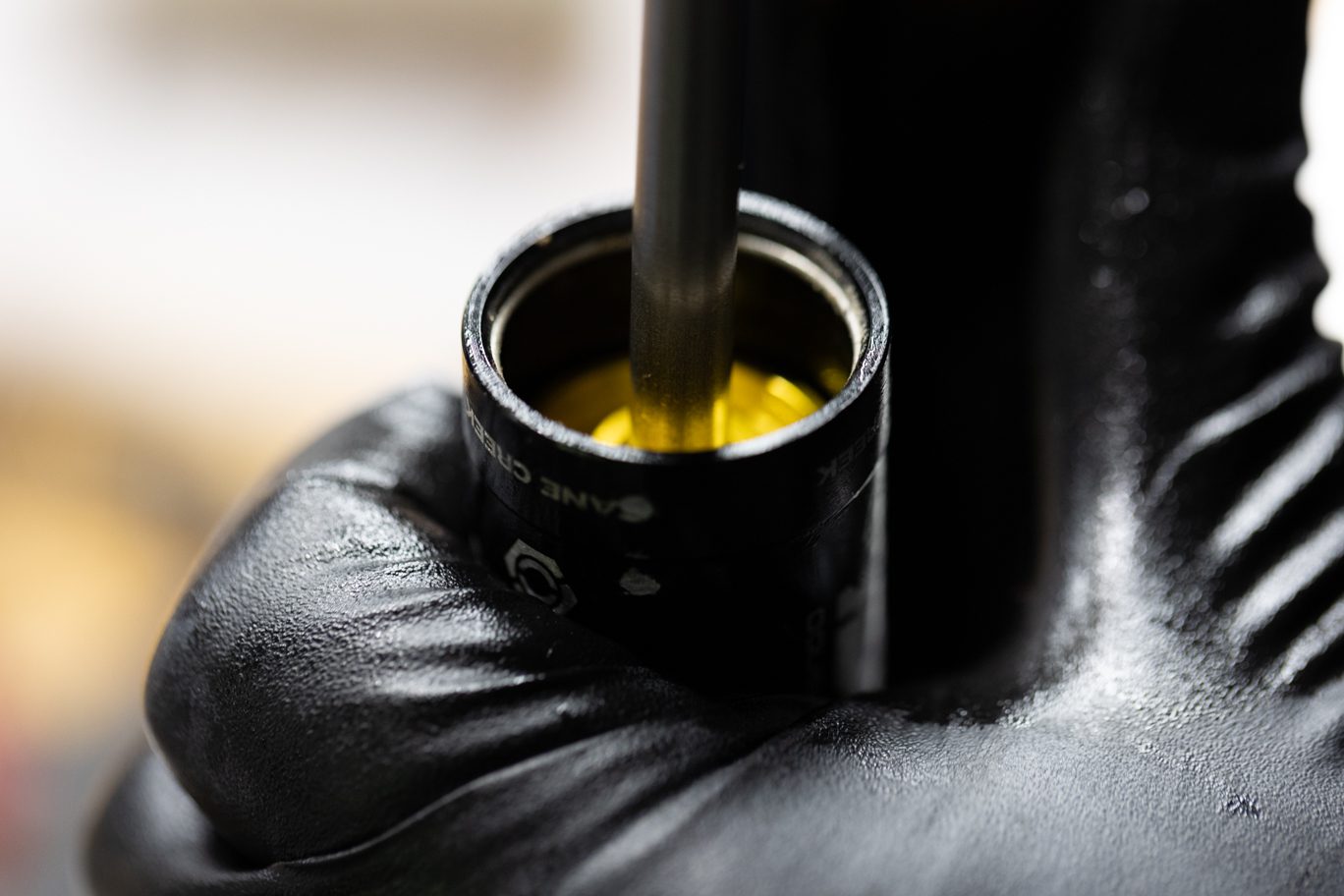
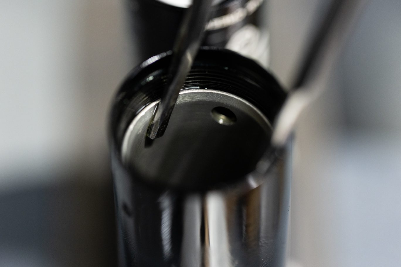
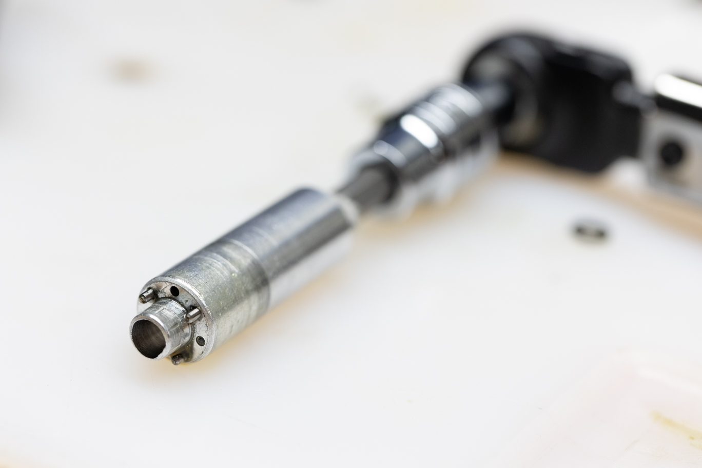
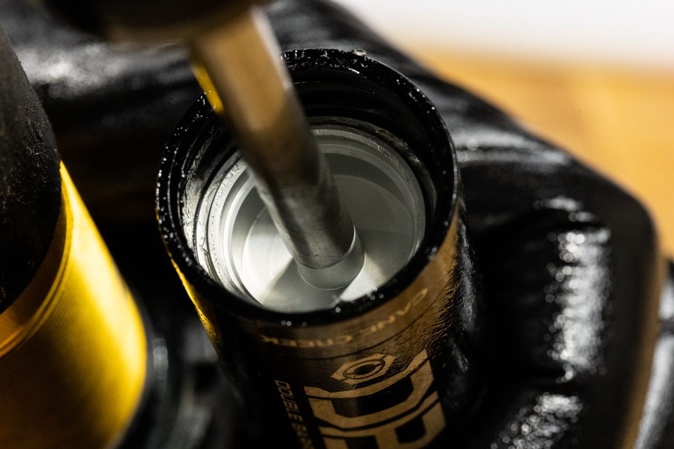
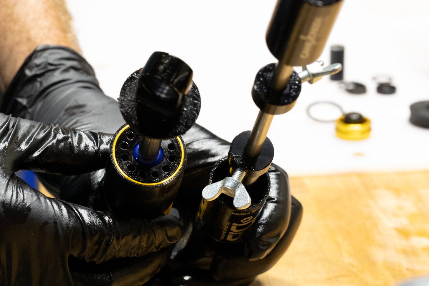
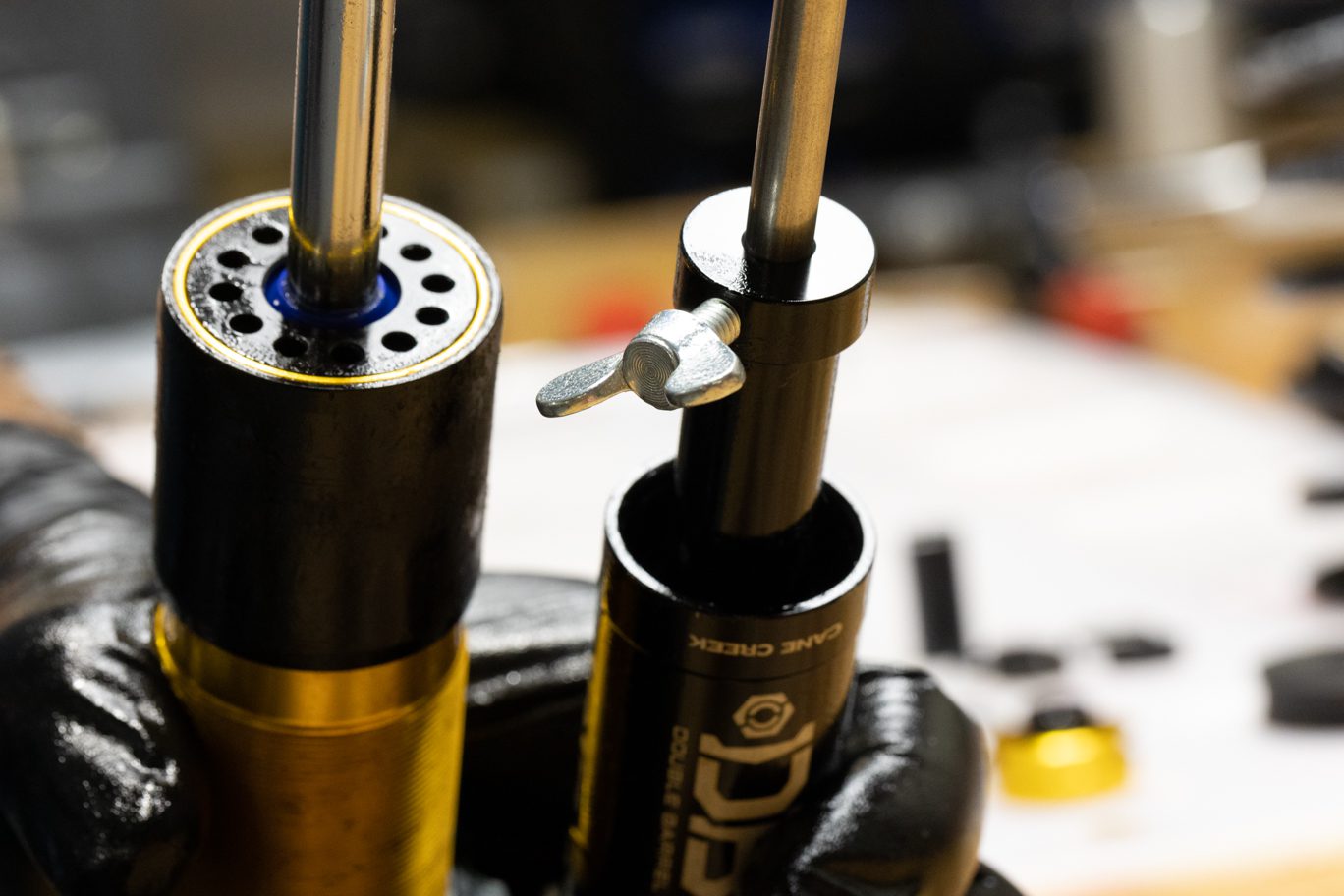
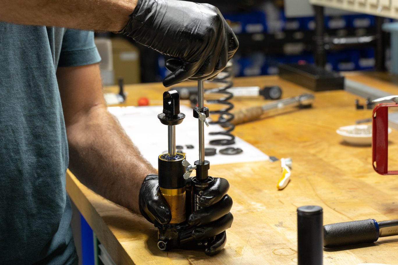
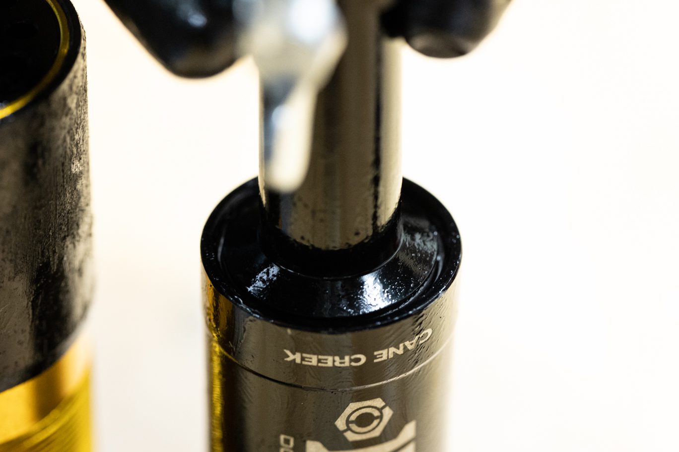
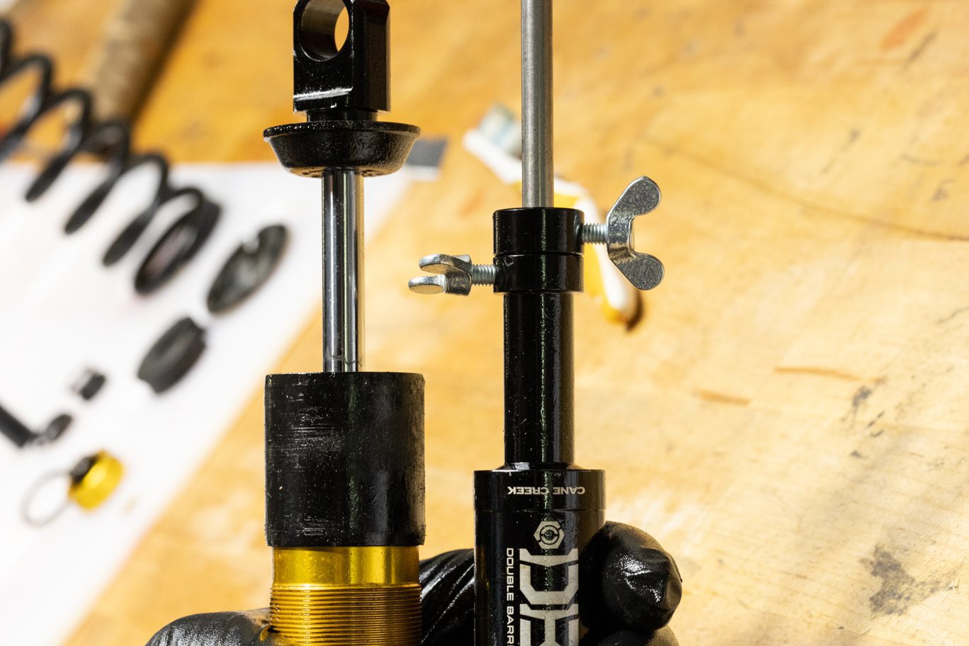
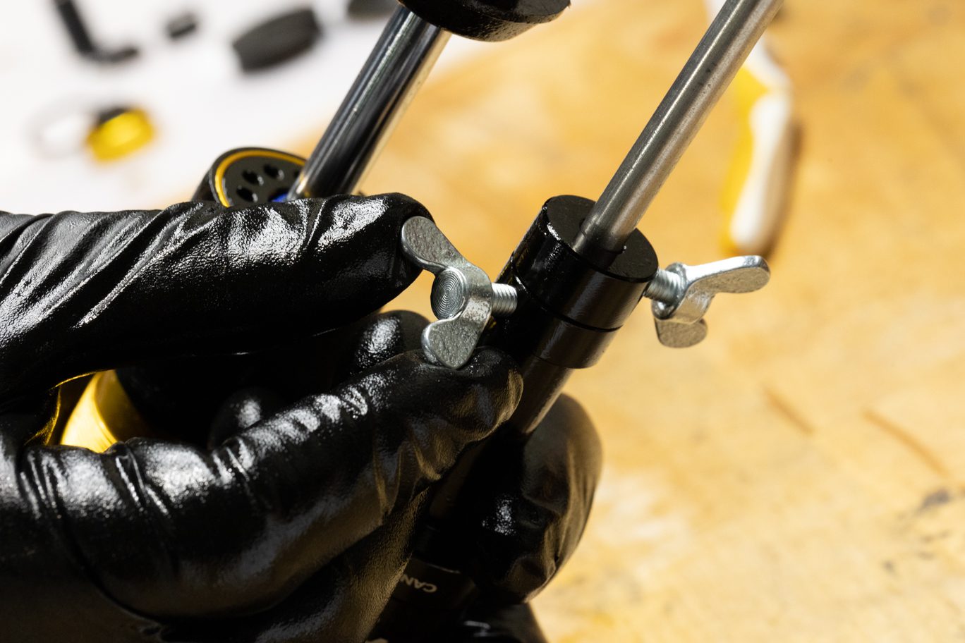
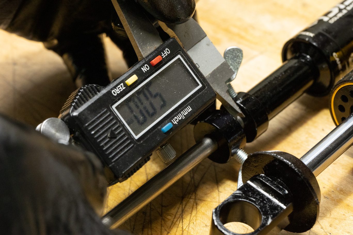
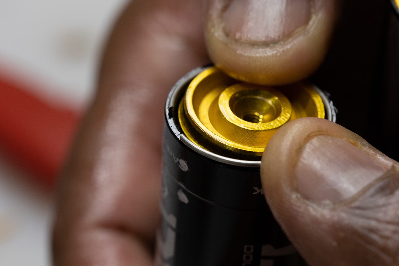
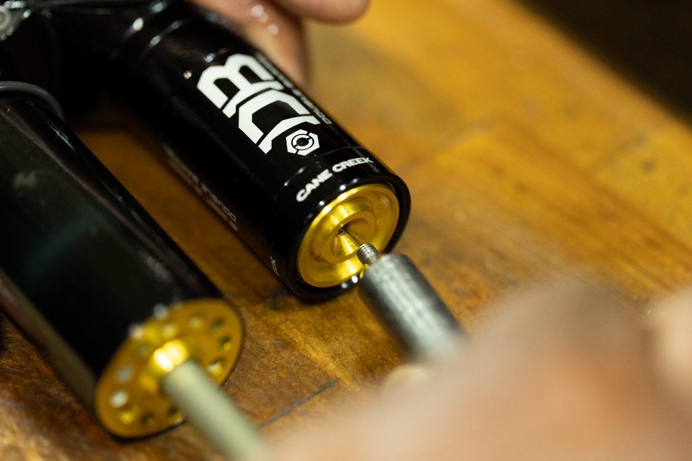
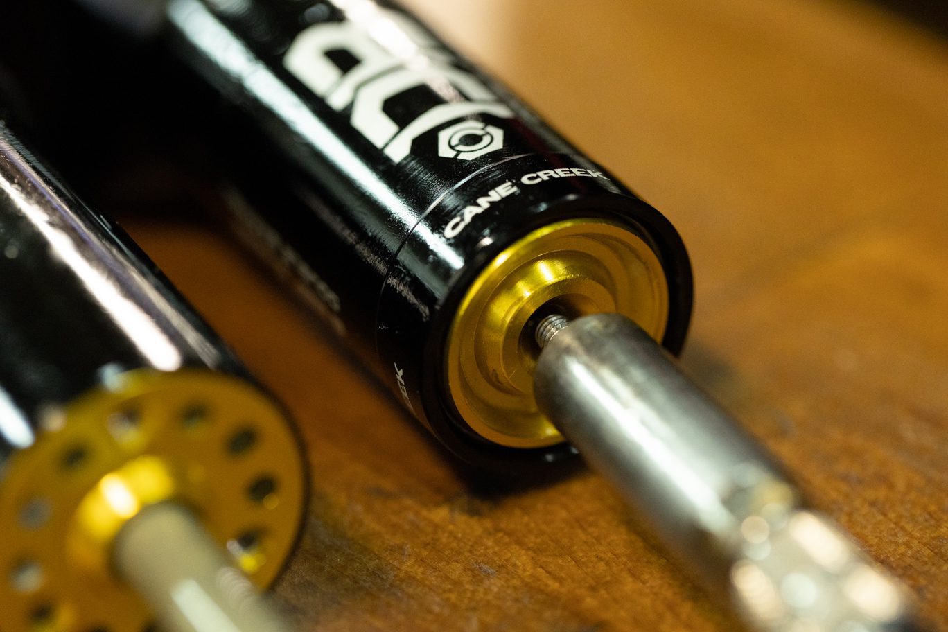
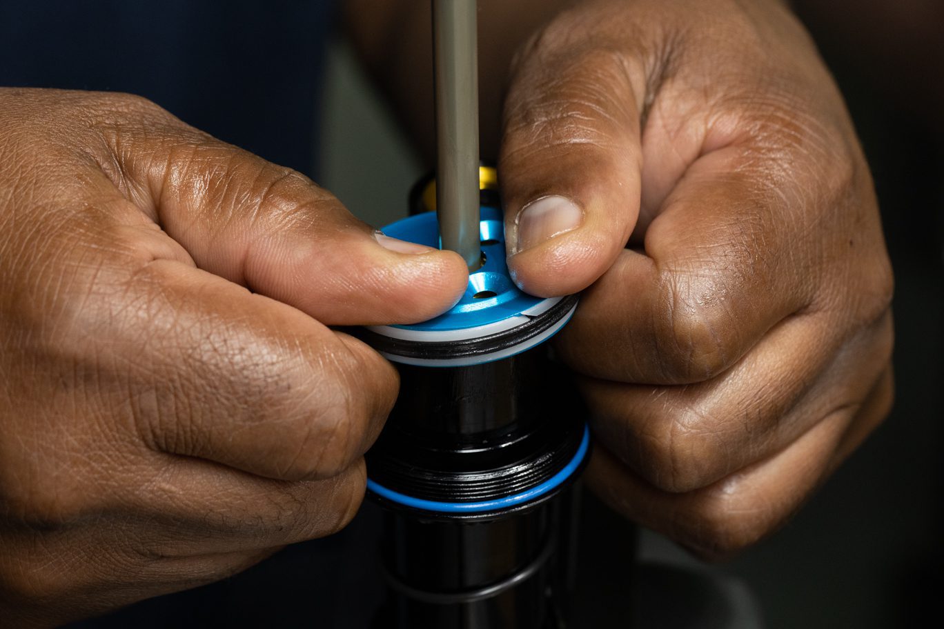
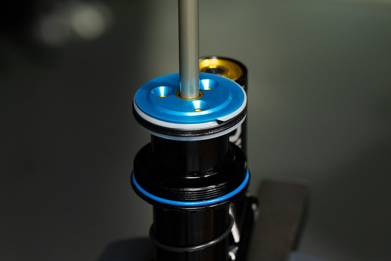
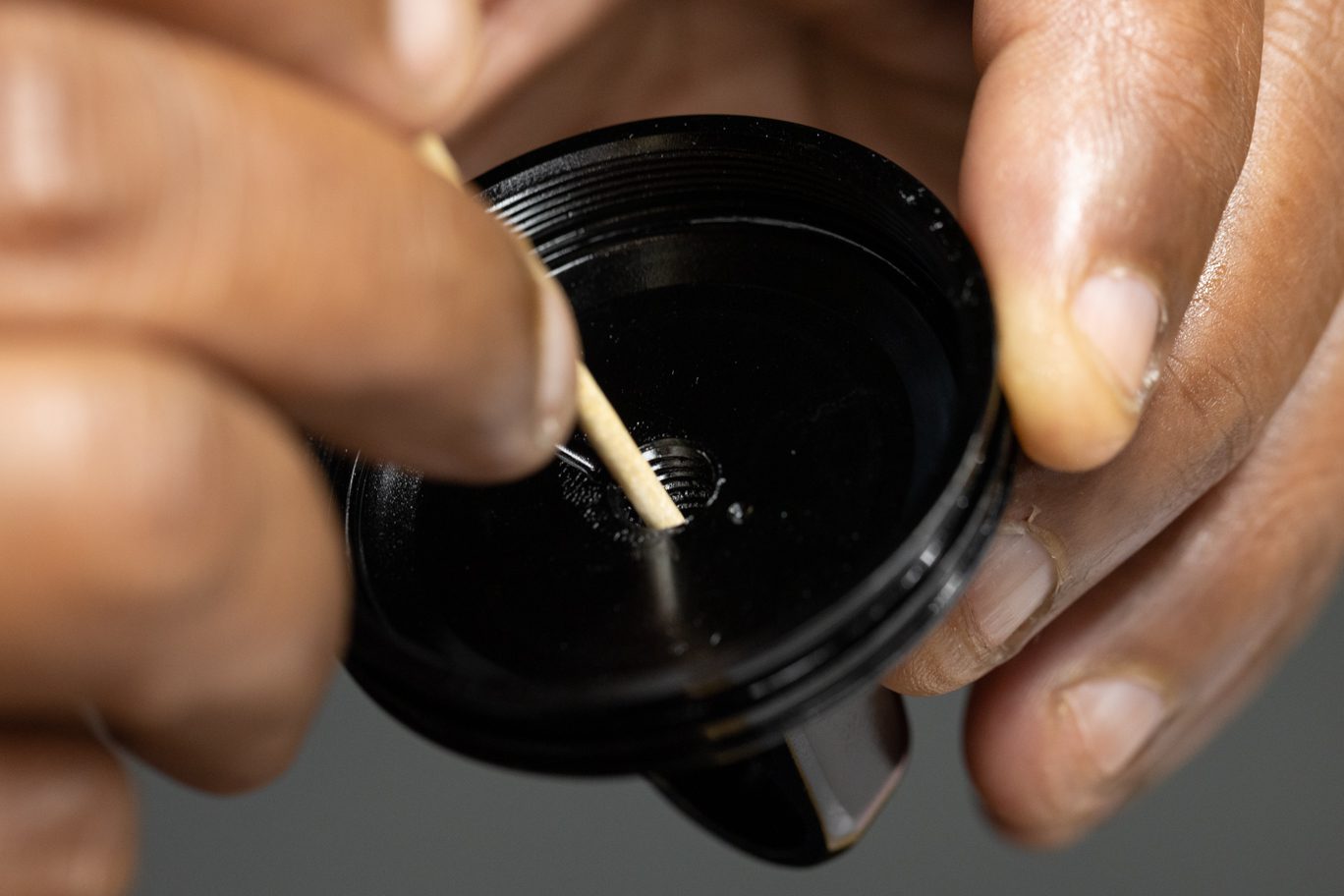
Thread IFP tool into IFP until bottomed. Push into reservoir tube until bottomed. Slide plunger into res tube. Install res end circlip. With IFP bottomed, slide the plunger out until contacting circlip. Lock plunger in place. Lock spacer in place onto top of plunger. Loosen plunger and pull IFP out 5mm. Relock plunger in position to set IFP depth.
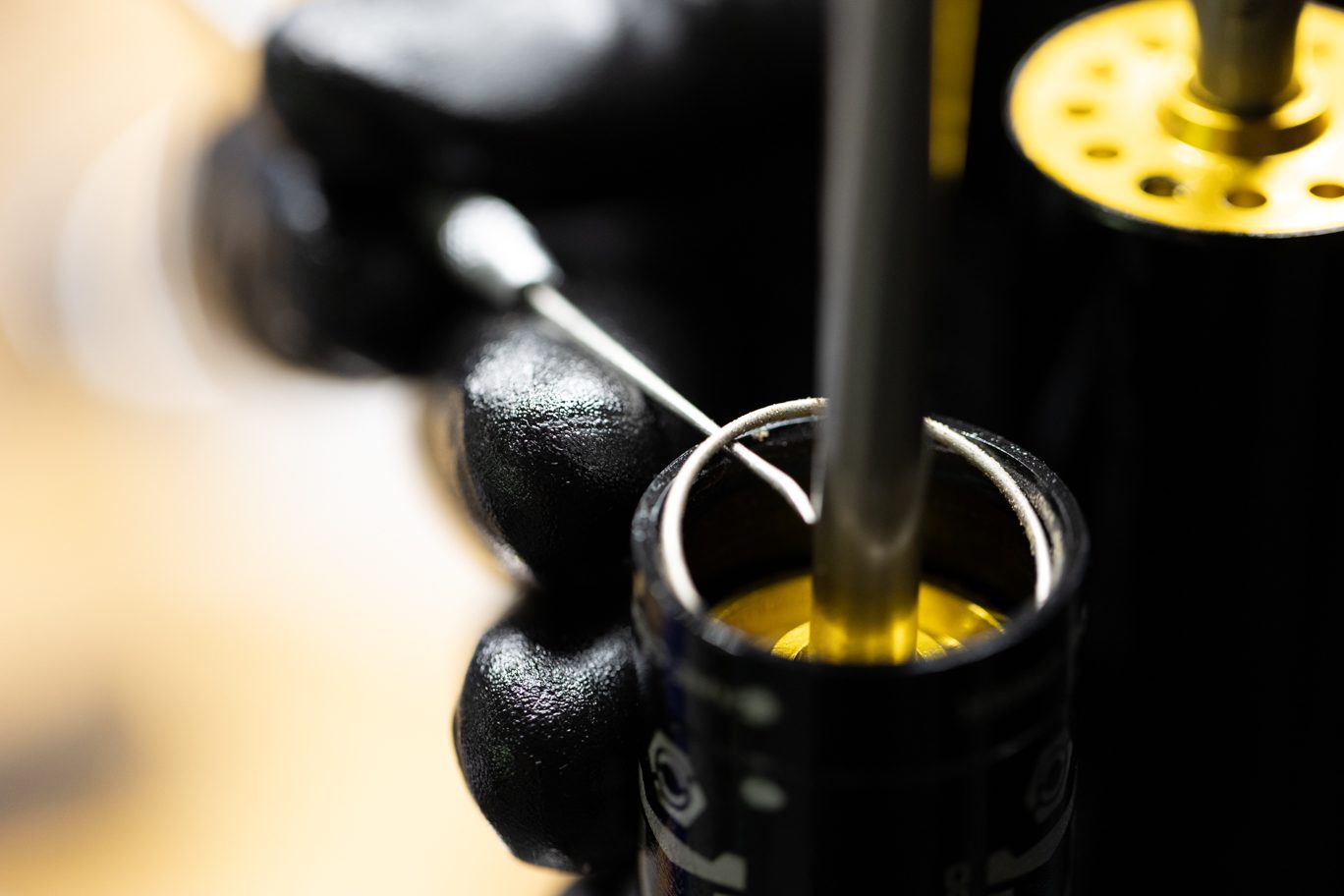
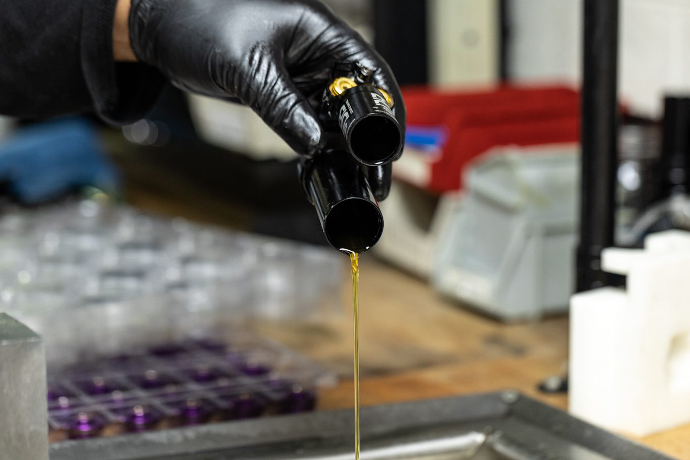
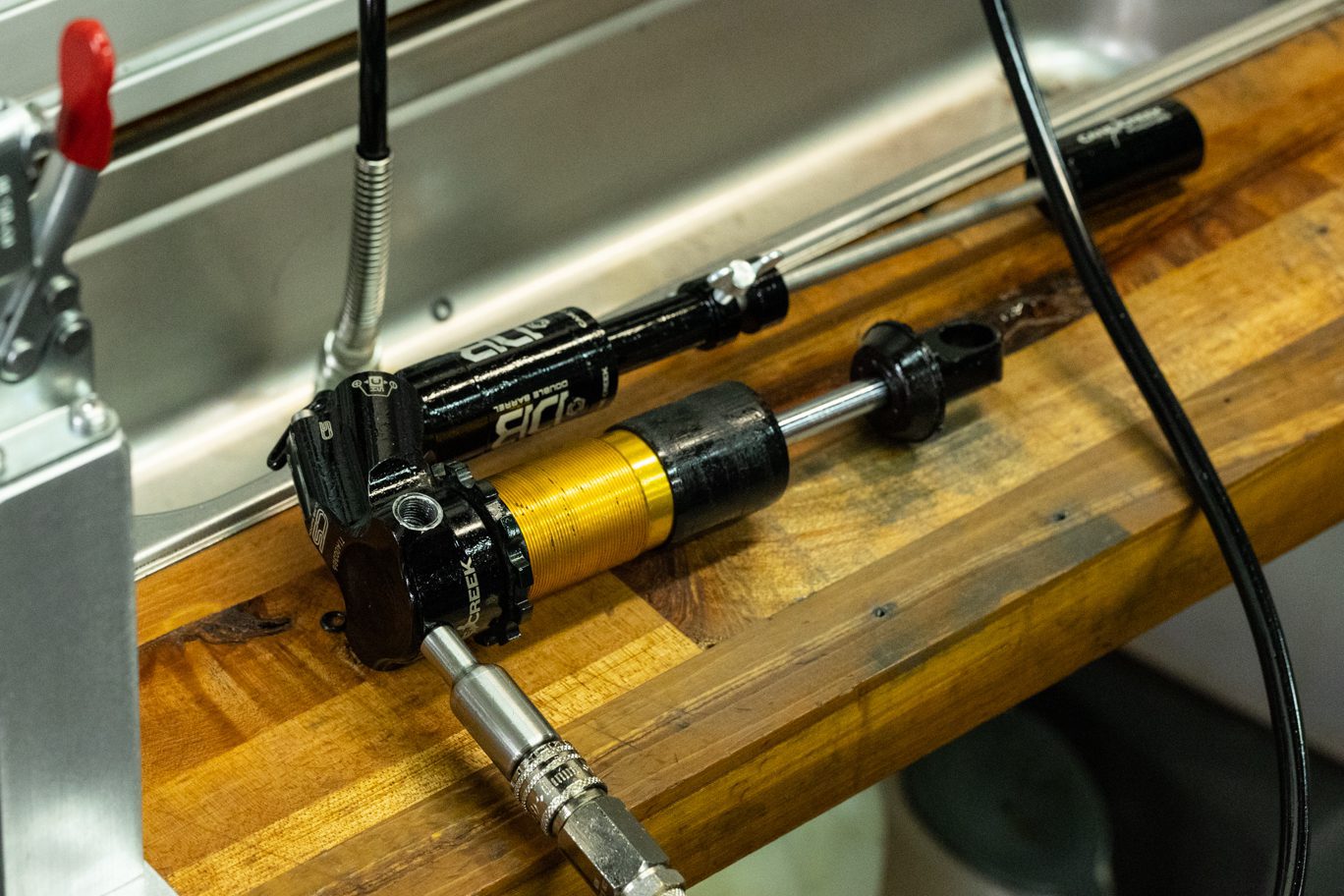
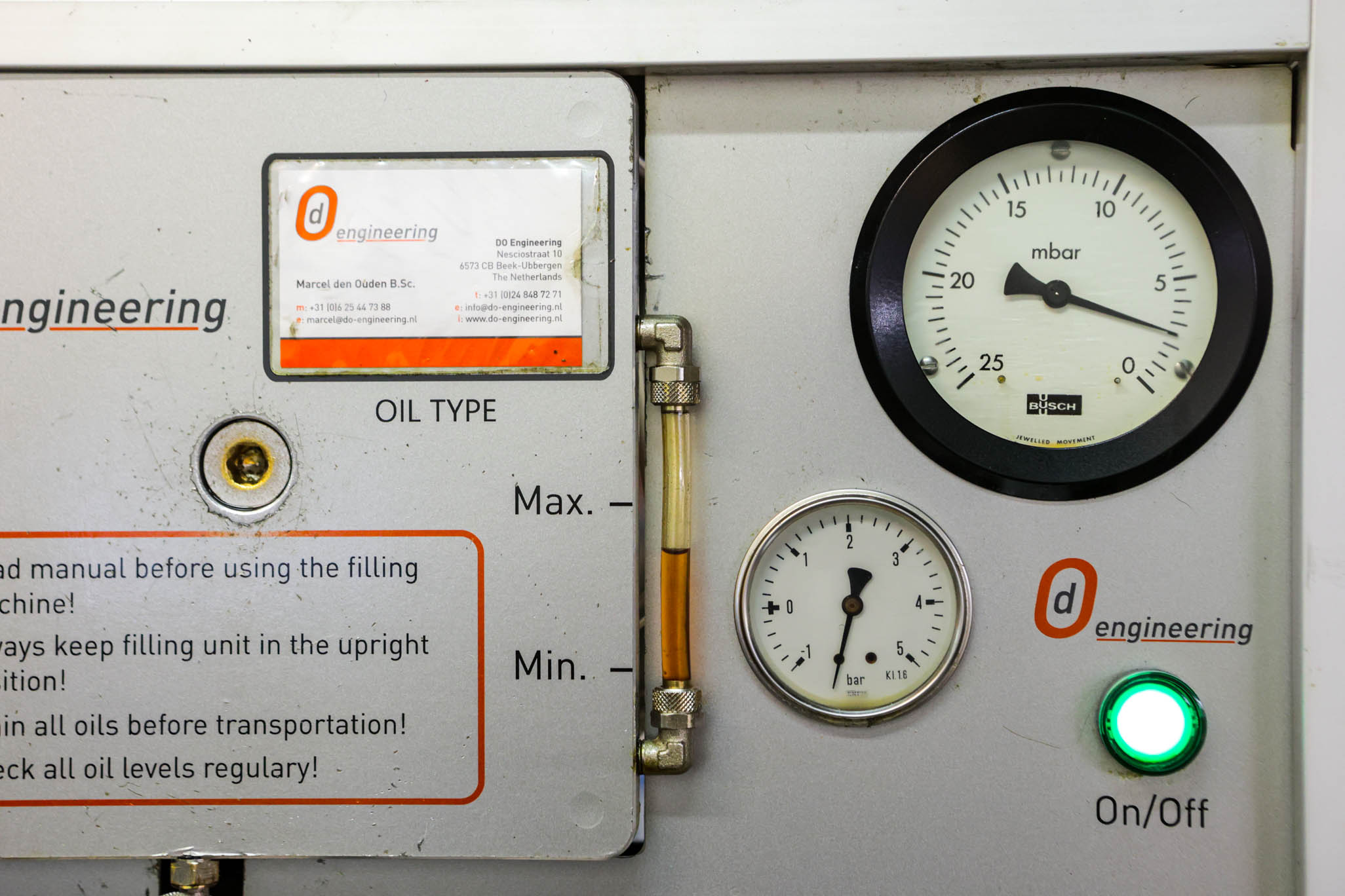
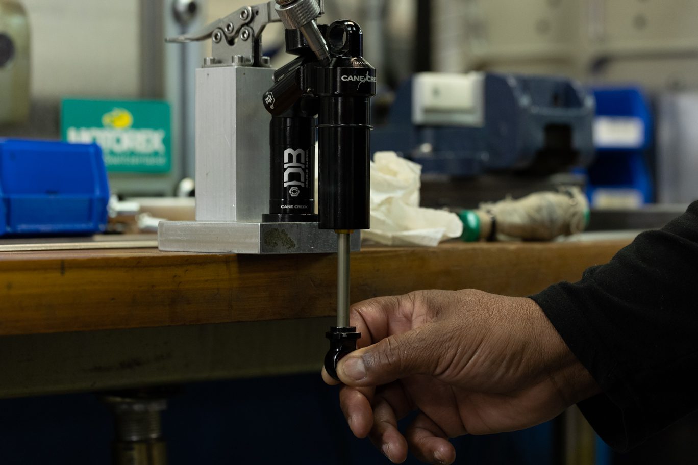
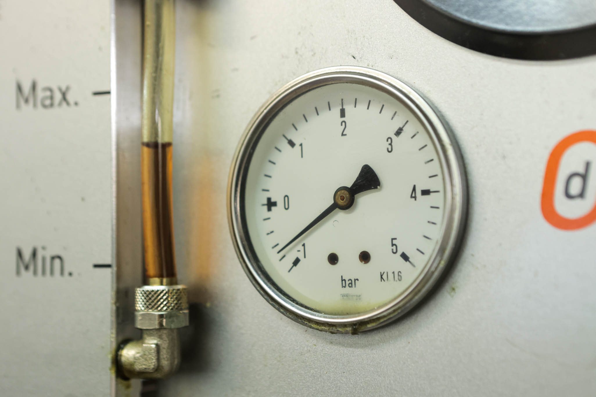
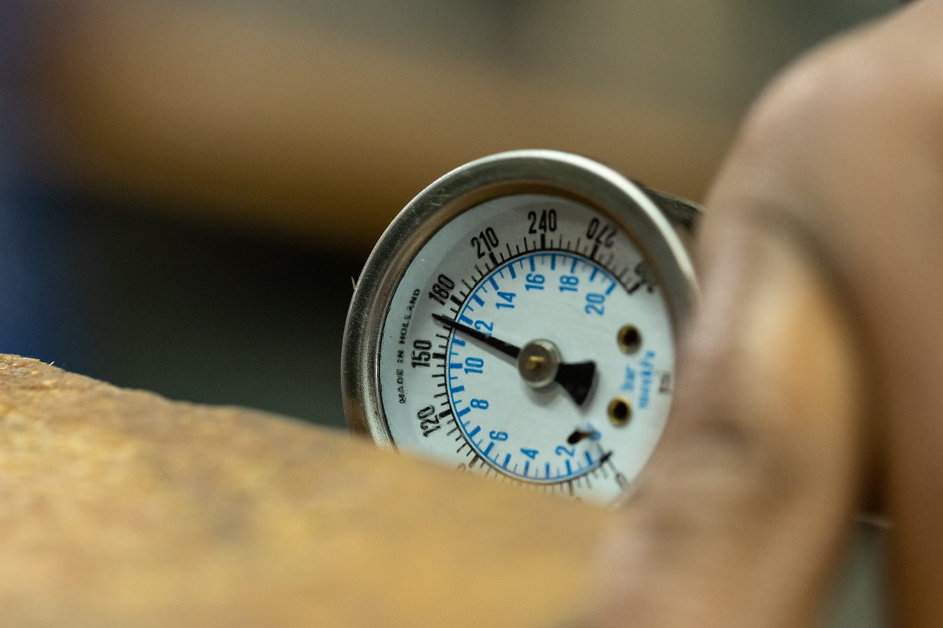
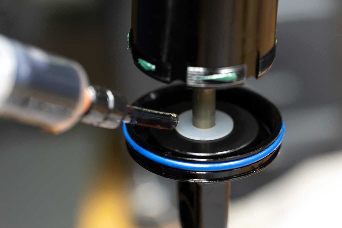
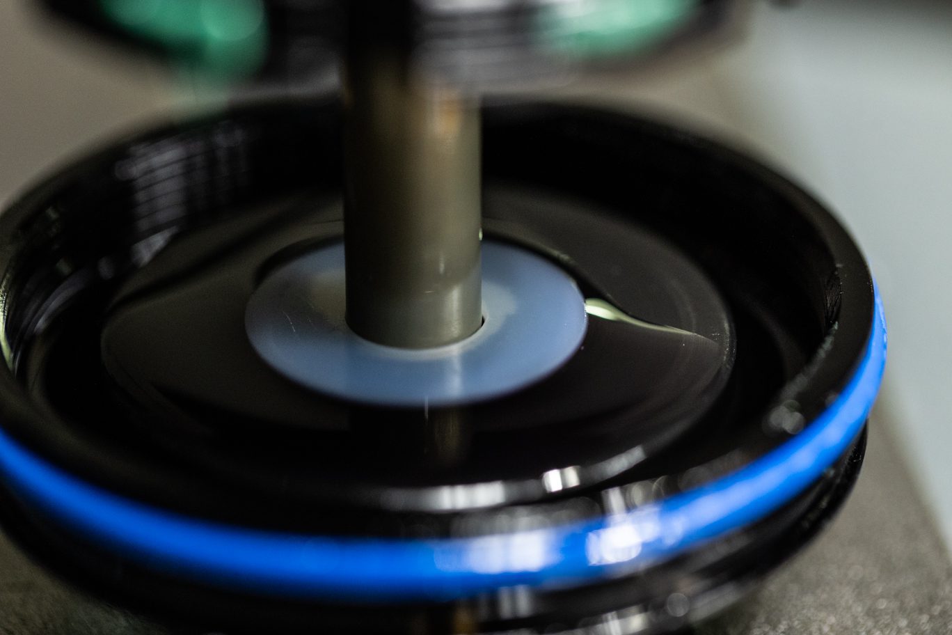
Vacuum system to (4) mbar. Pressure with Oil to (3) bar. Slowly cycle shaft finishing with shaft fully out. Cut fill and equalize pressure. Vacuum system to (4) mbar, leaving shaft out. Pressure again with Oil to (3) bar. Slowly cycle shaft finishing with shaft fully out. Cut fill.
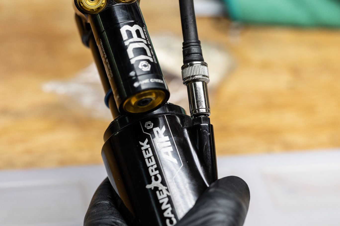
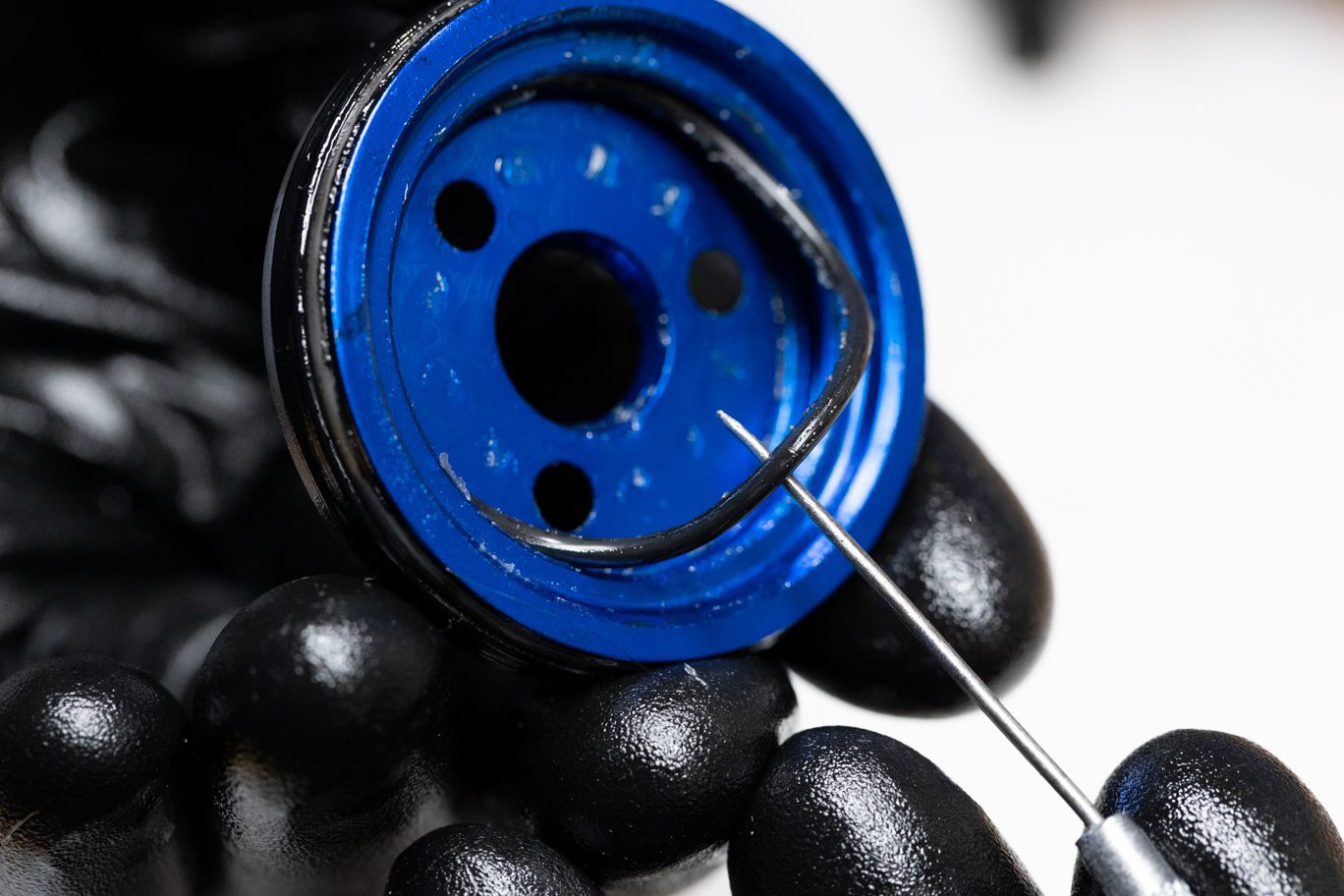
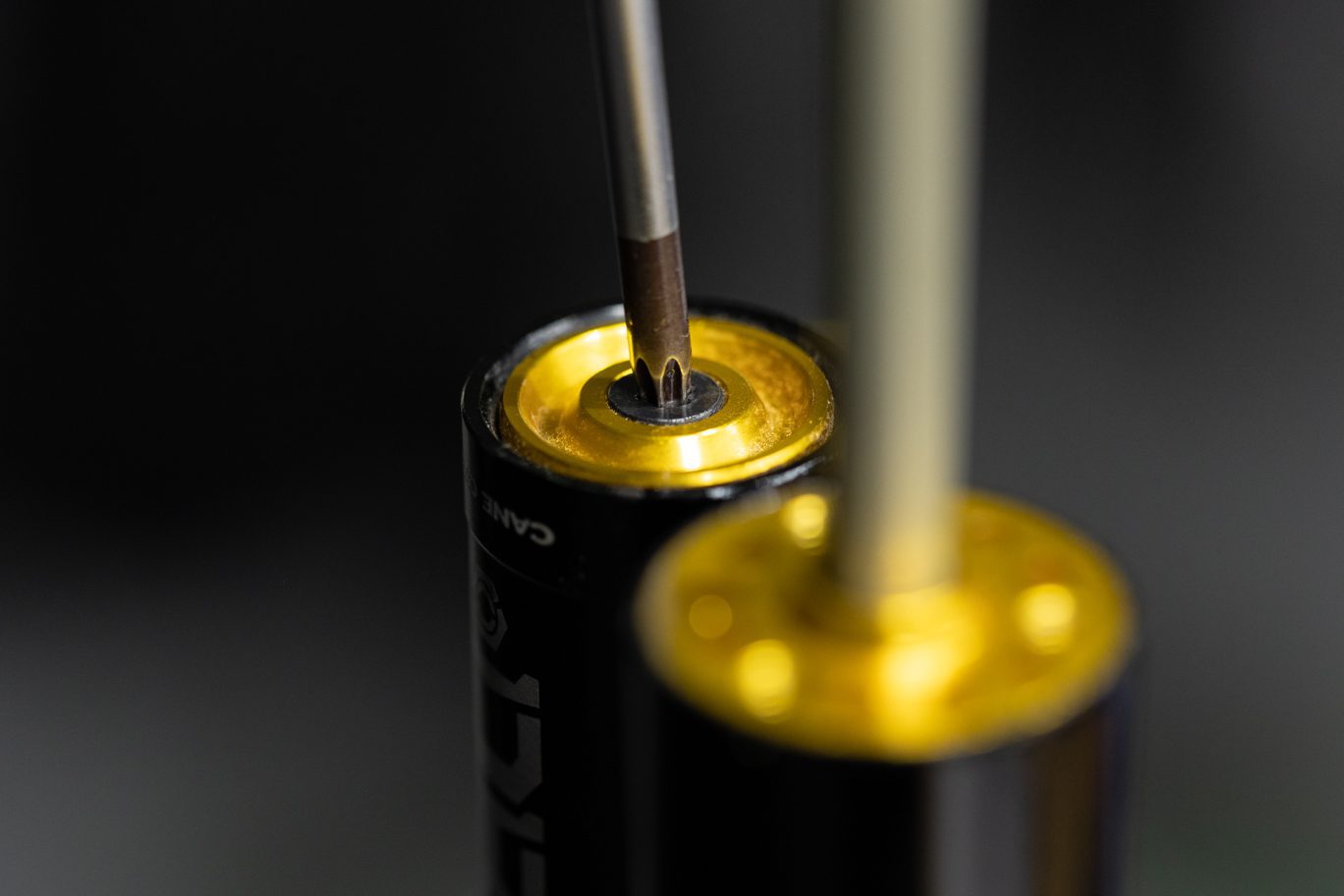
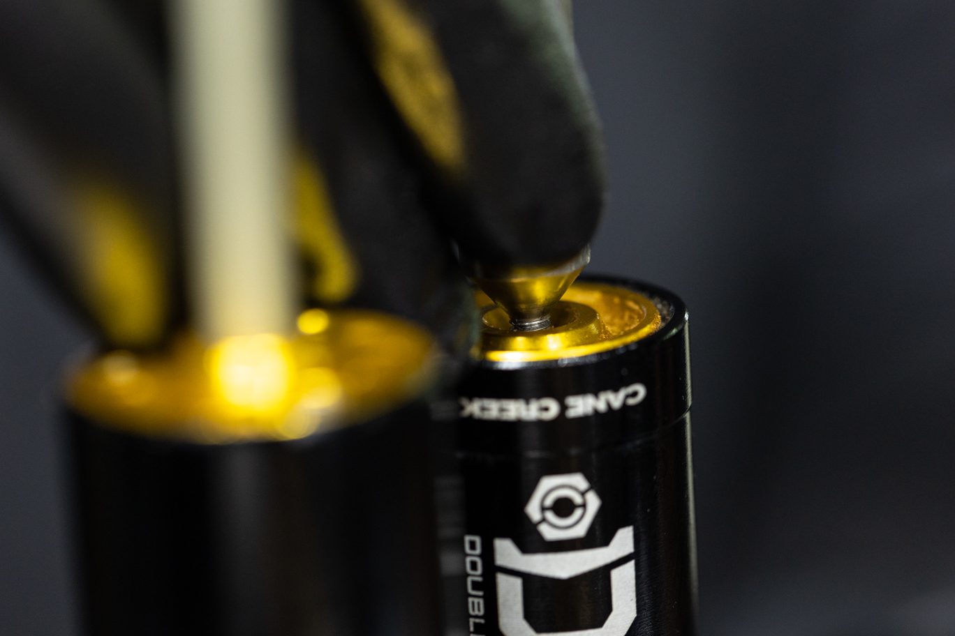
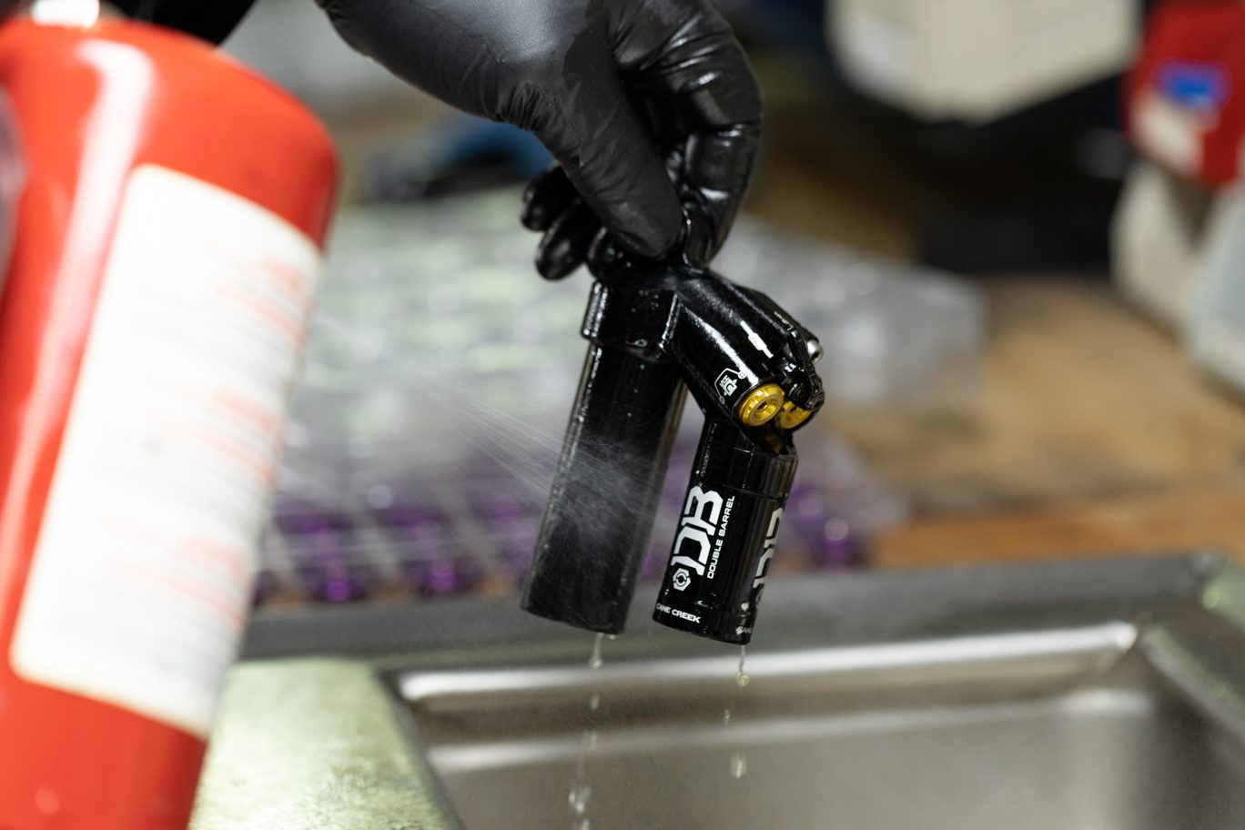
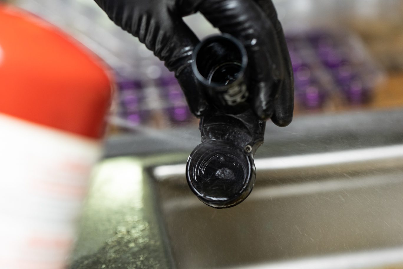
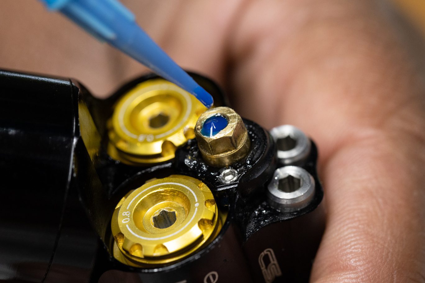
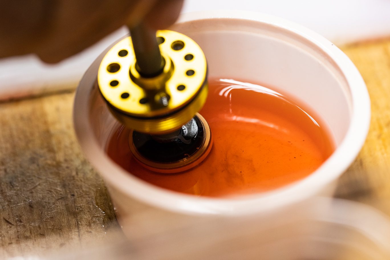
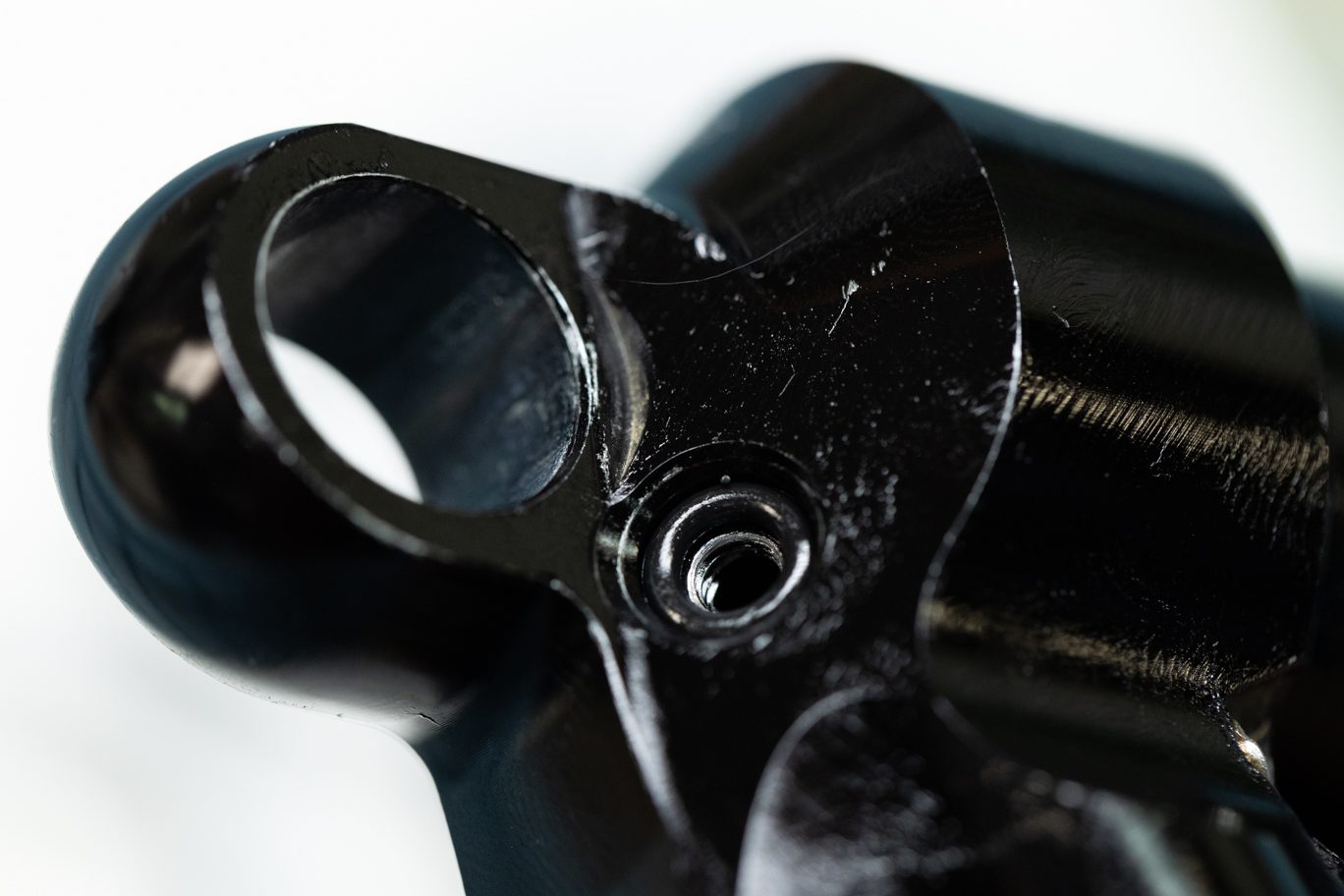
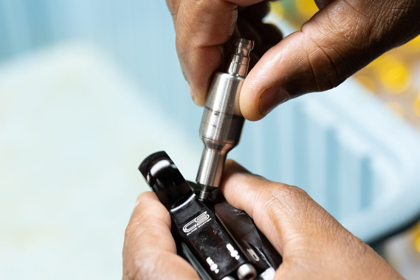
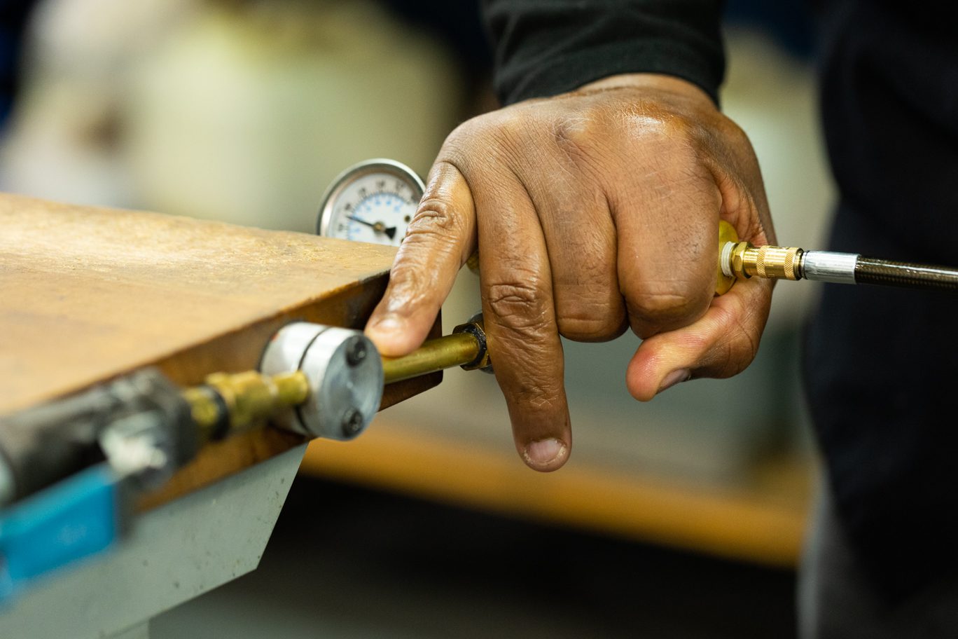
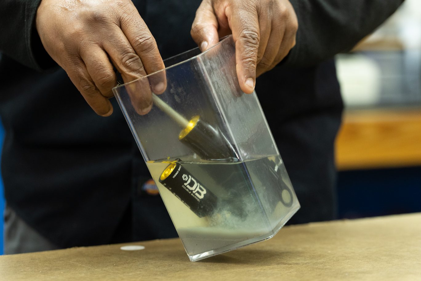
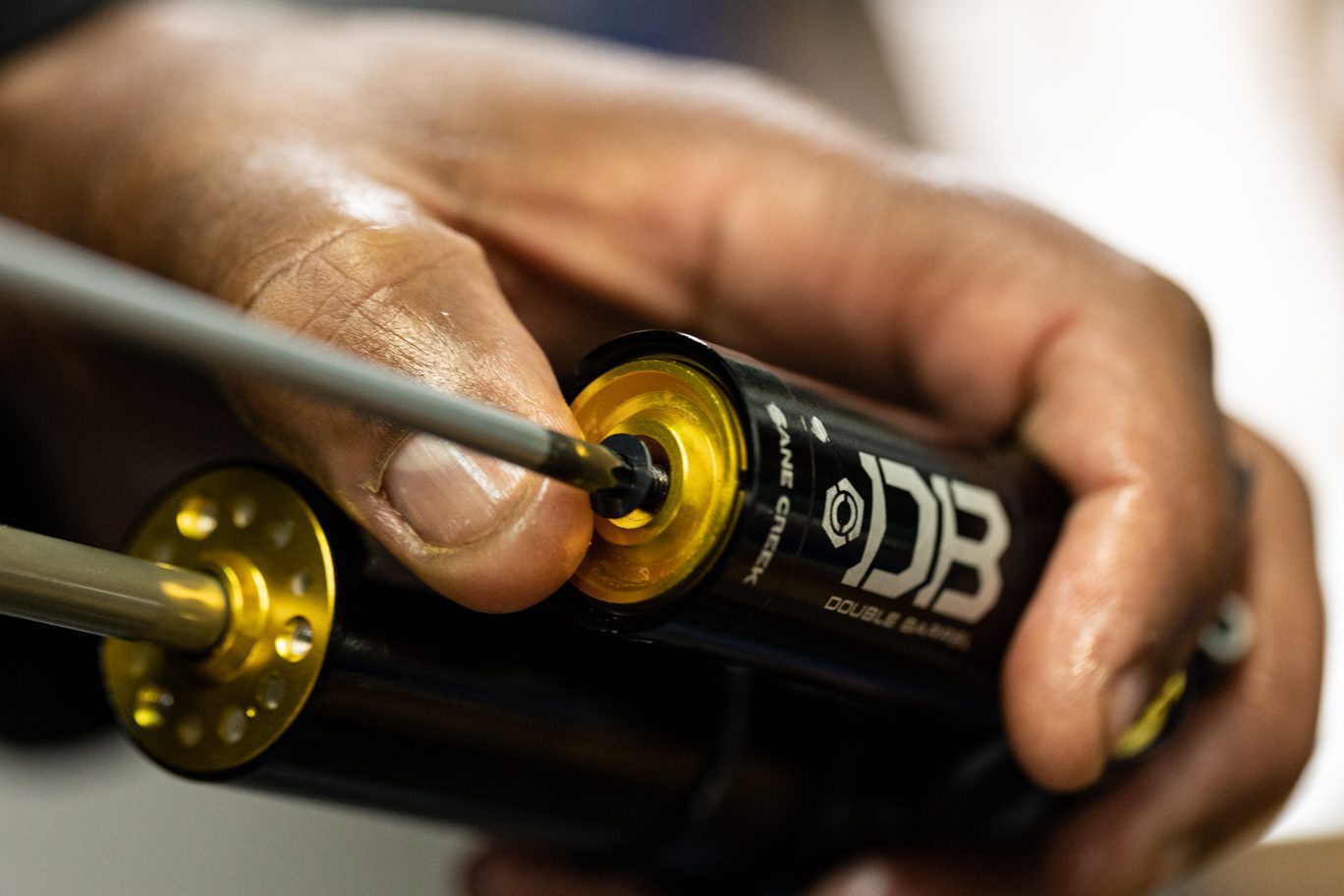
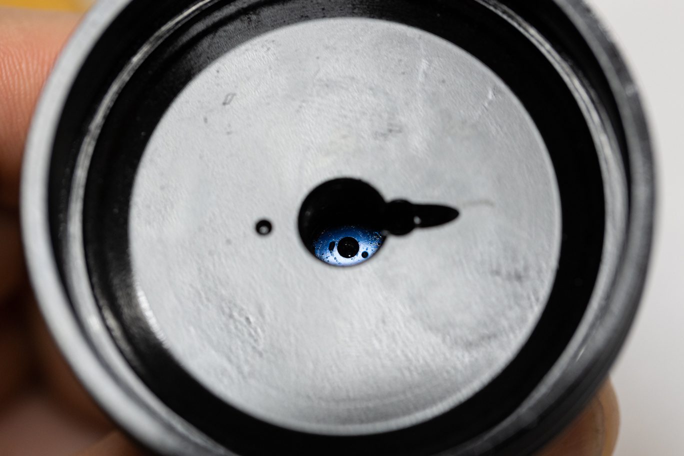
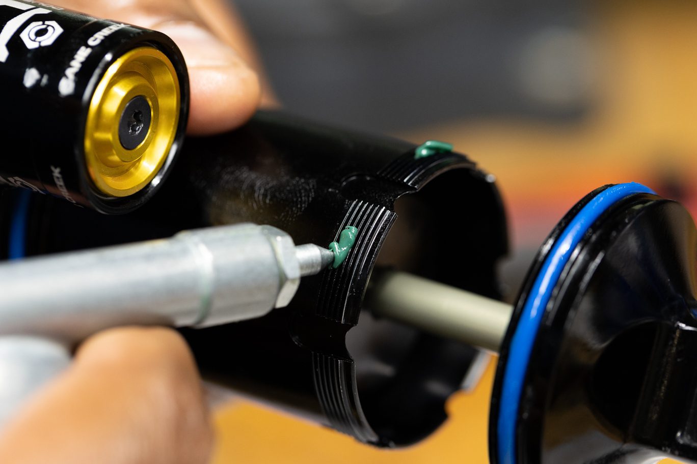
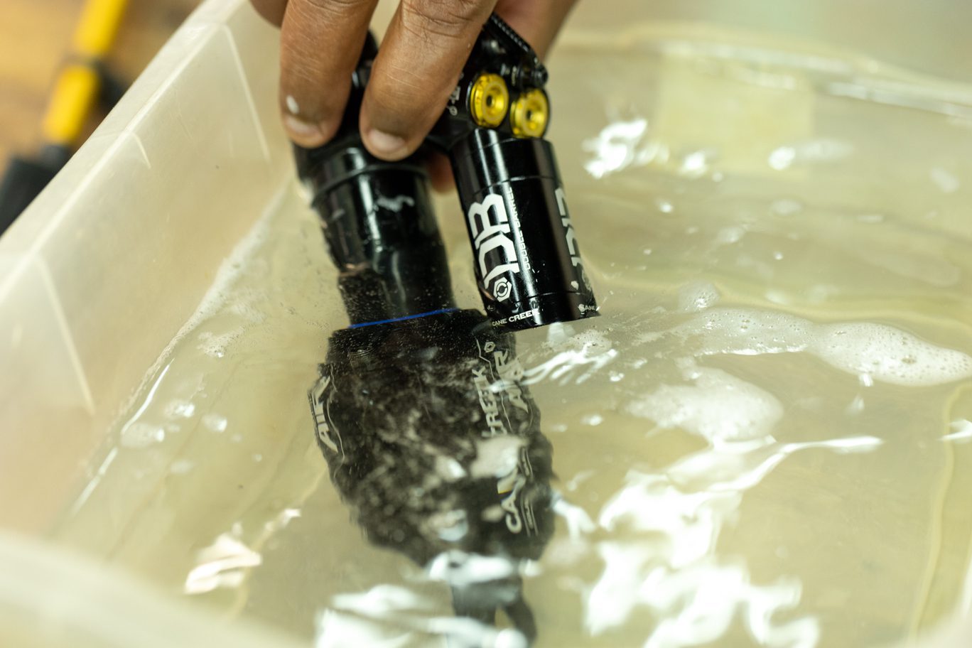
Insert gas fill needle in gas fill port on reservoir end cap. Pressurize to 11-12 bars of nitrogen. Compress shaft and ensure proper gas by observing shaft return to full extension. Submerge valve body in water to check for gas leaks. Install fill screw.
If mechanic dyno equipment is available, run shock on dyno at this point.
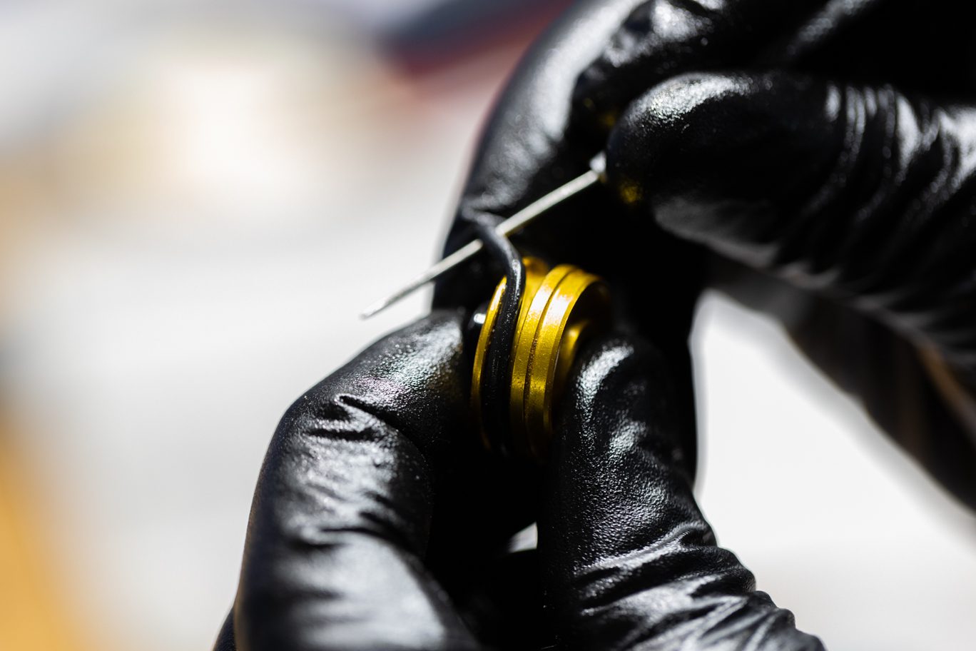
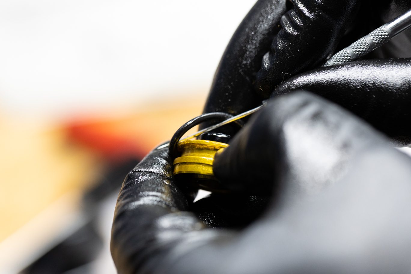
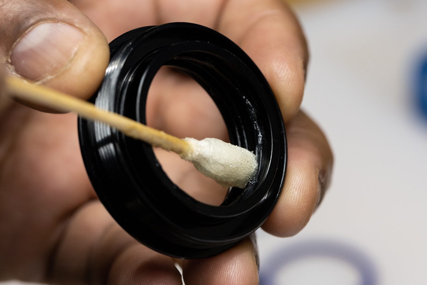
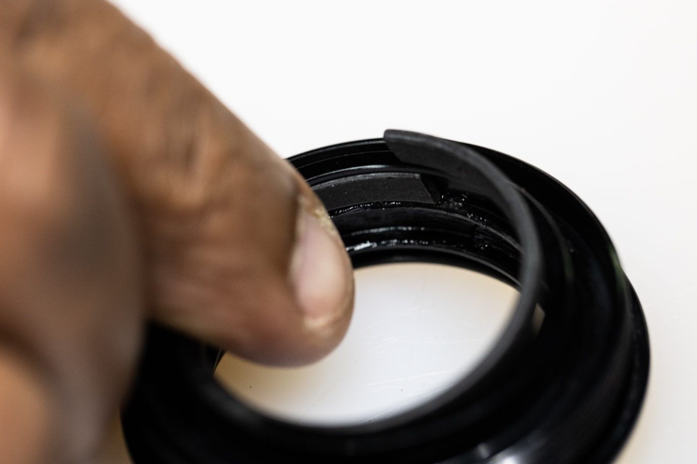
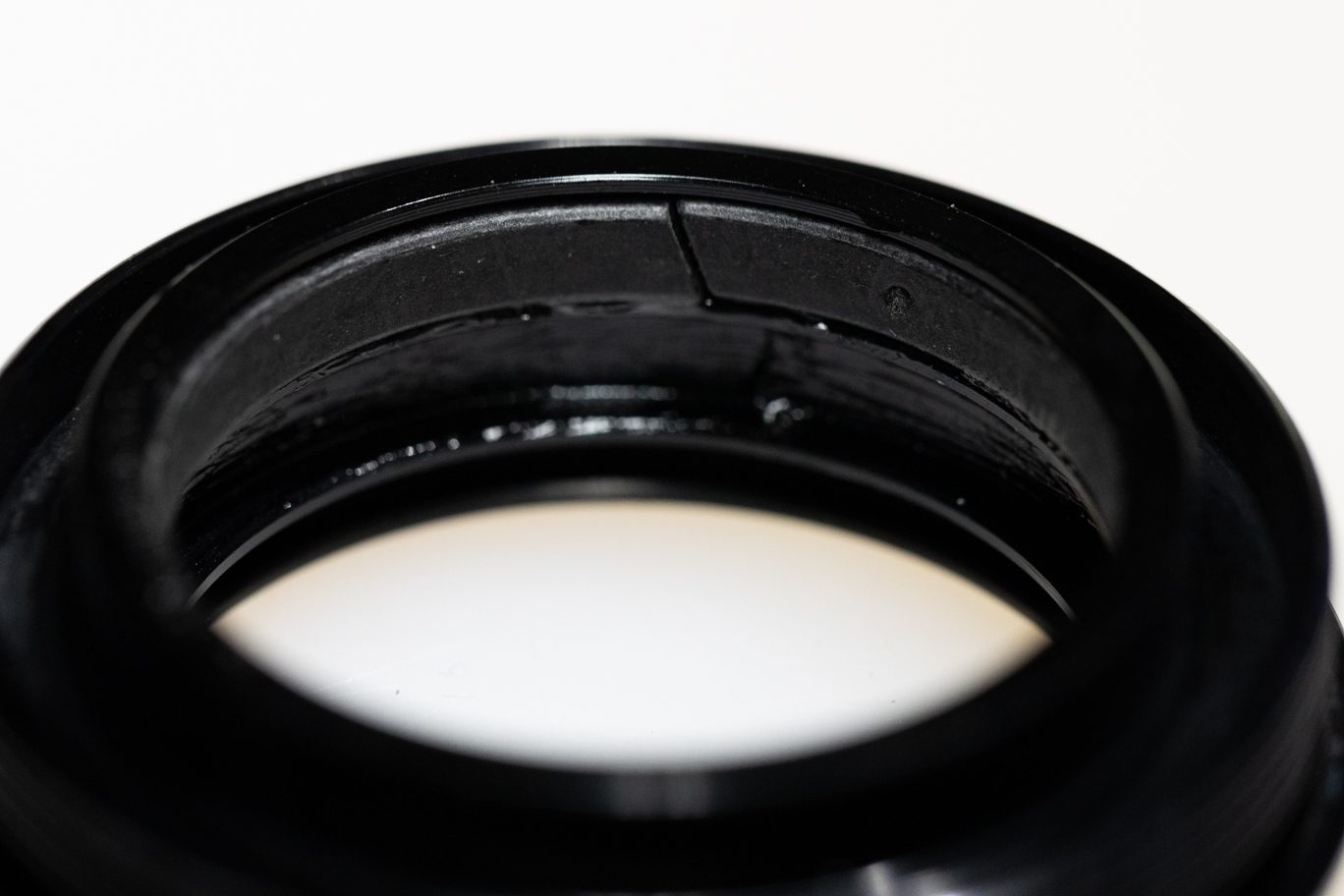
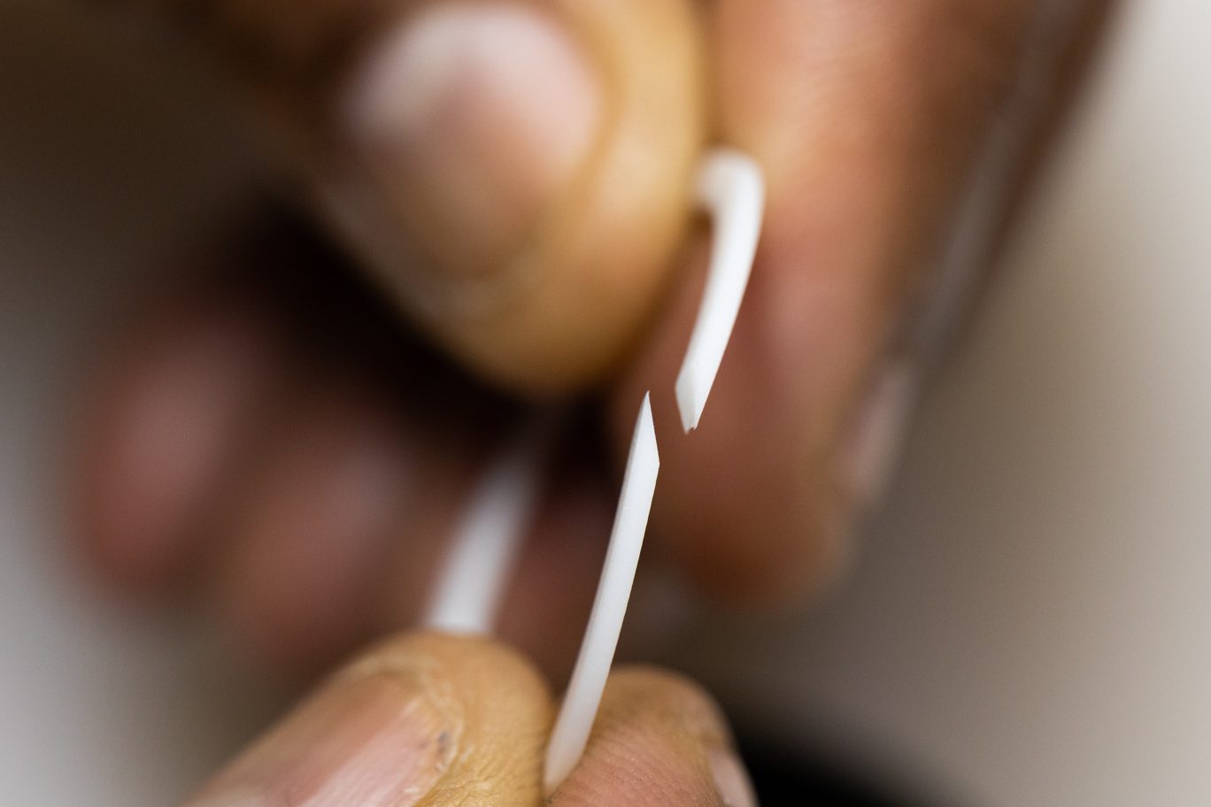
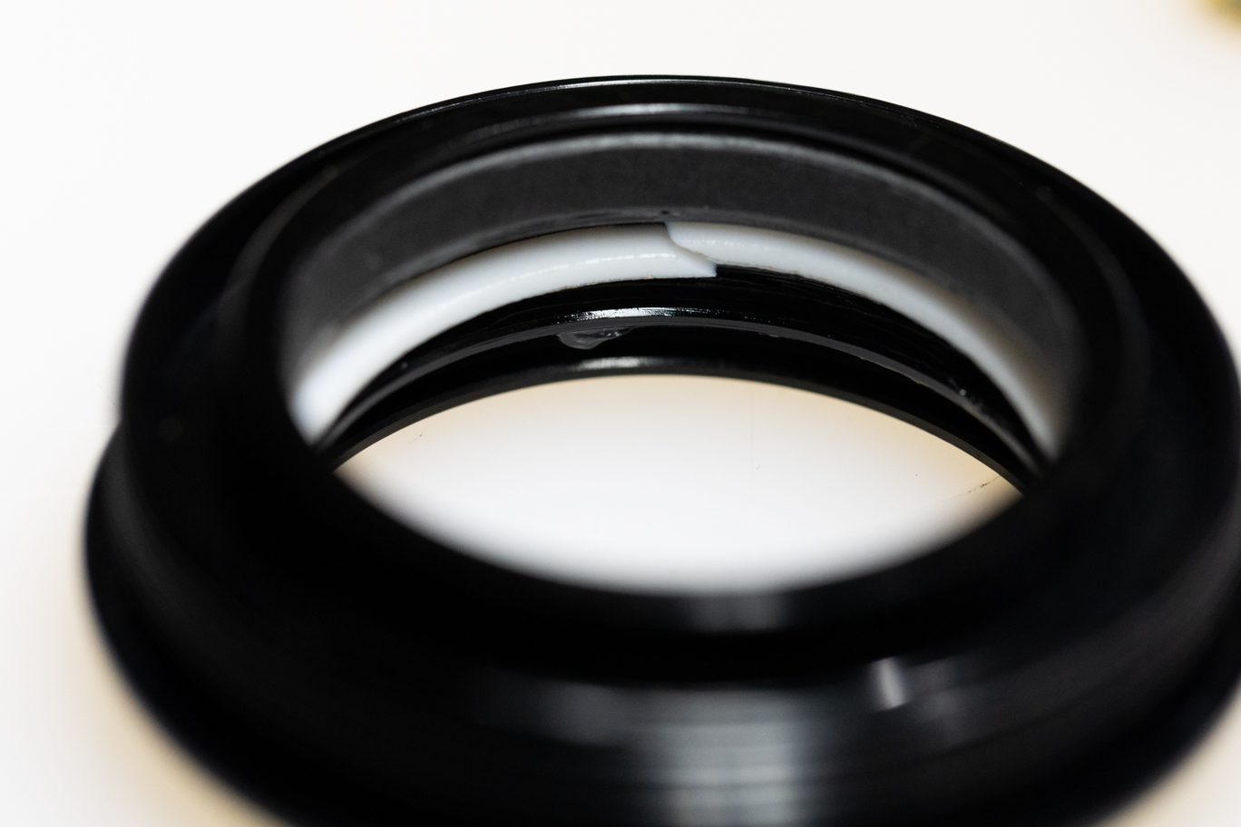
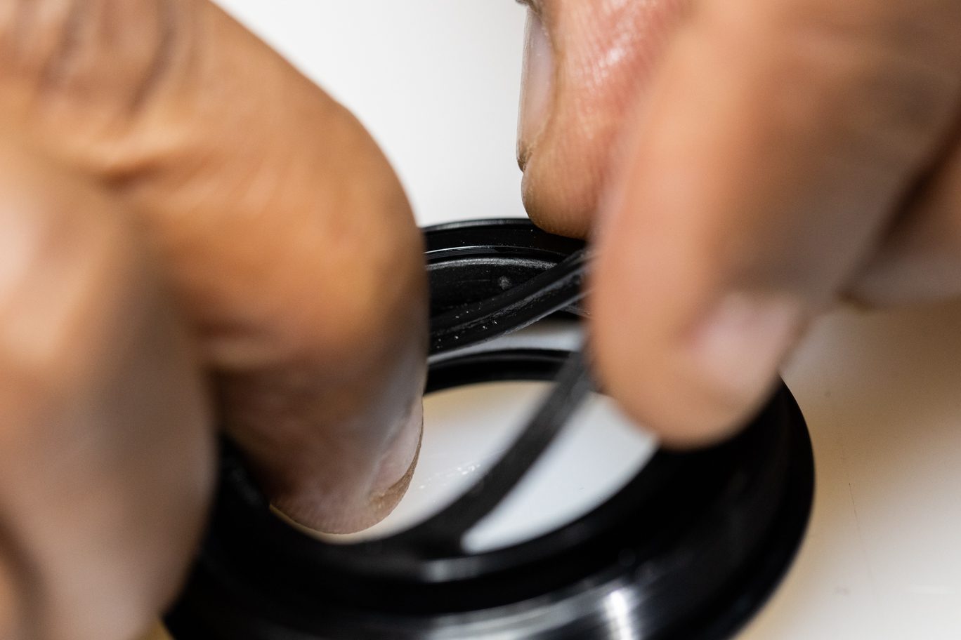
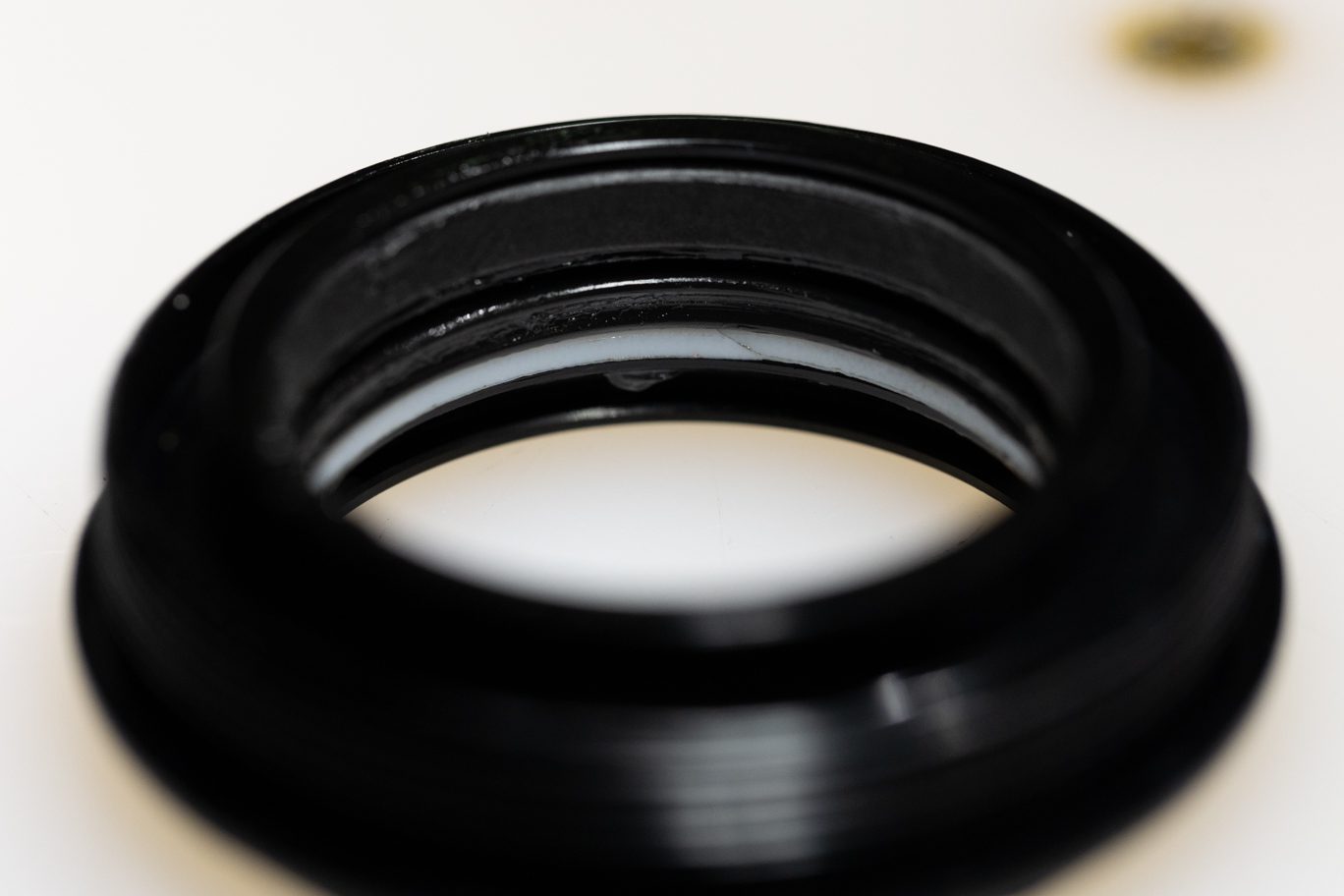
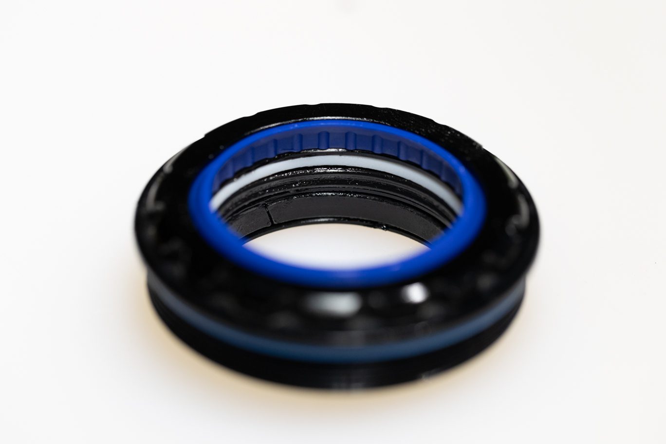
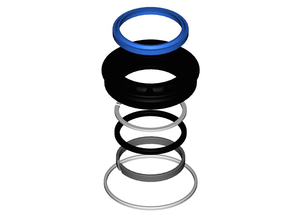
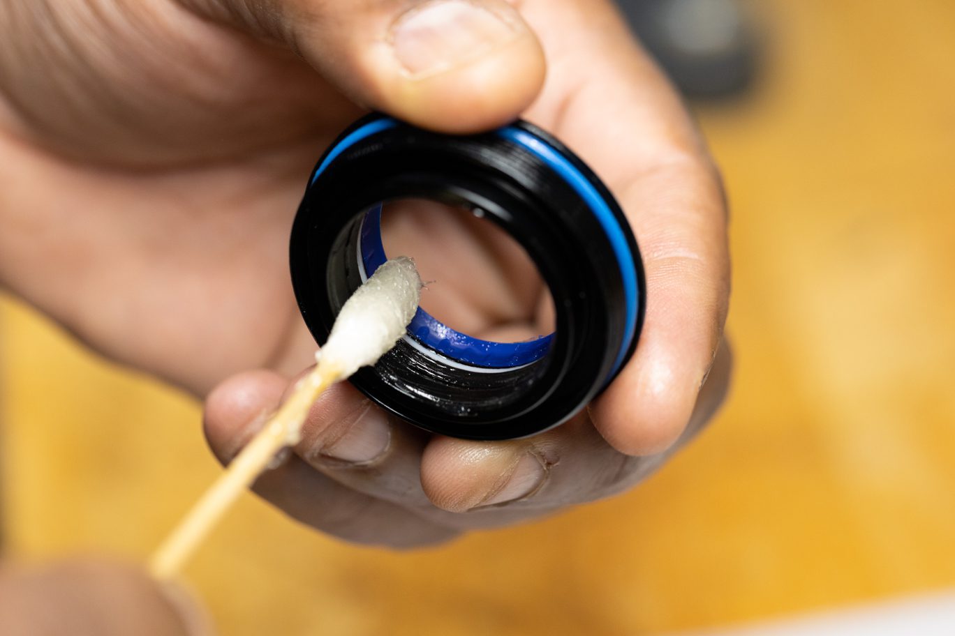
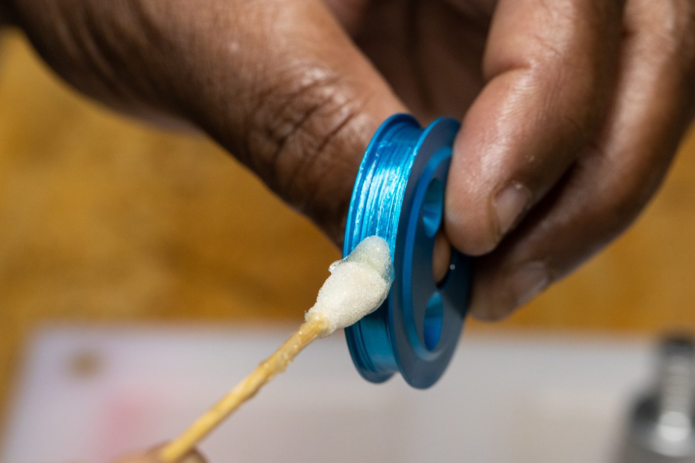
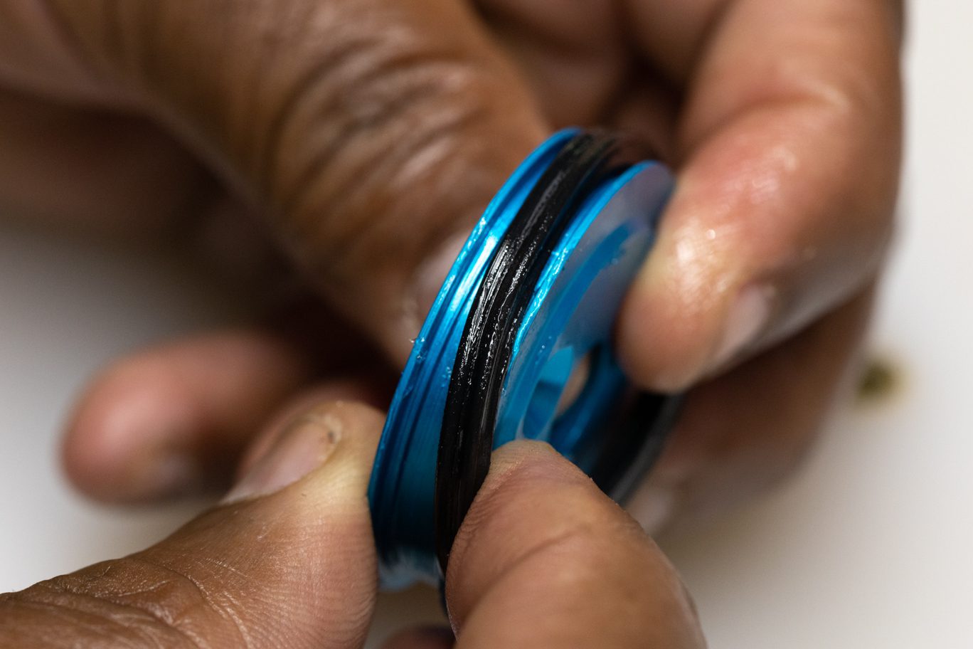
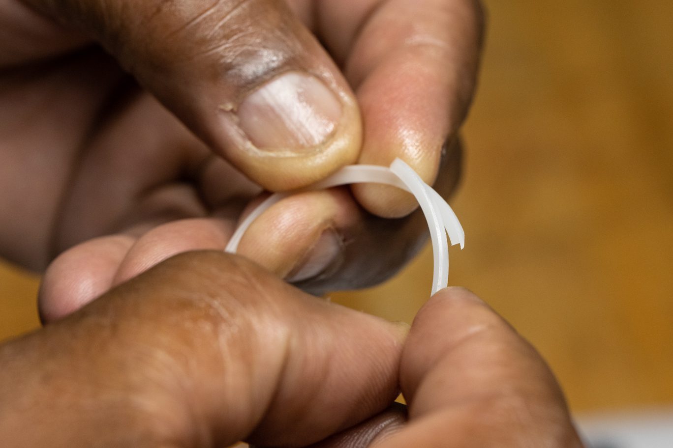
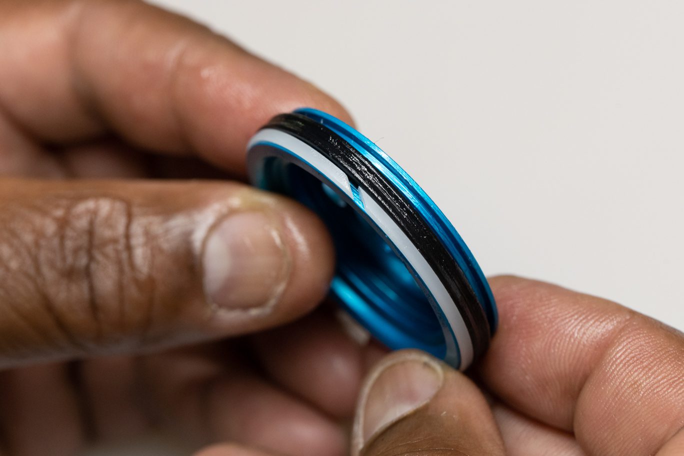
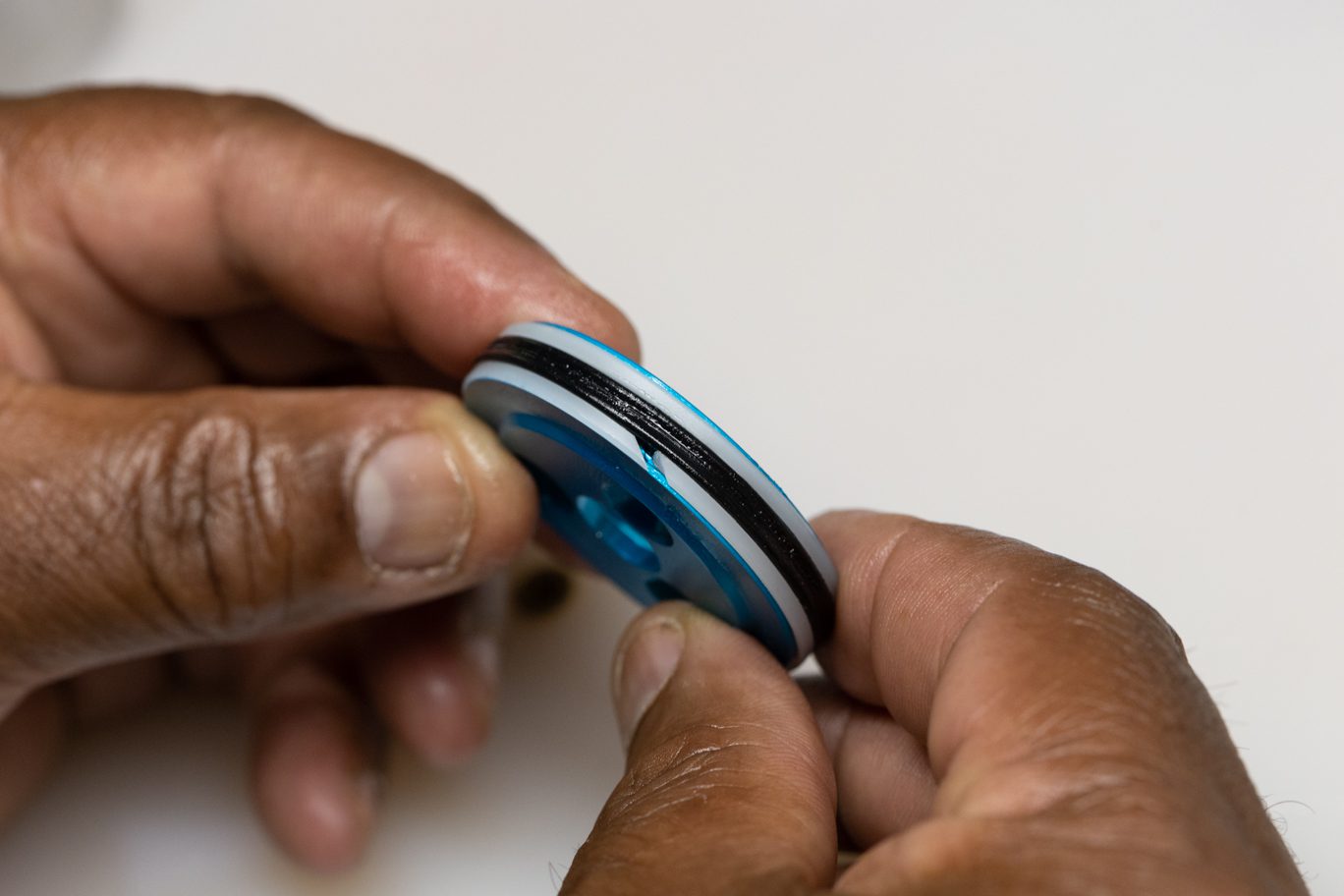
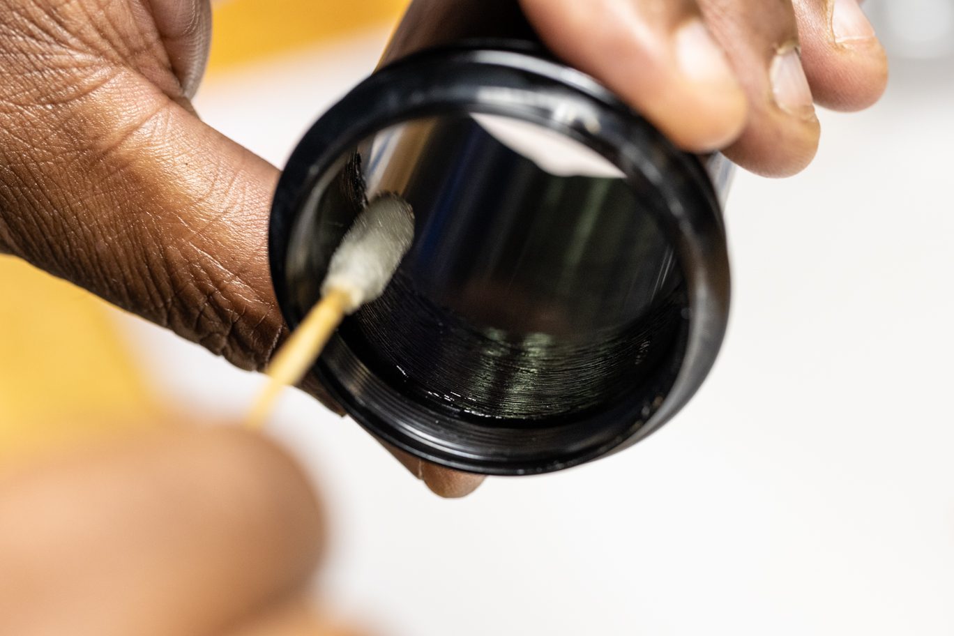
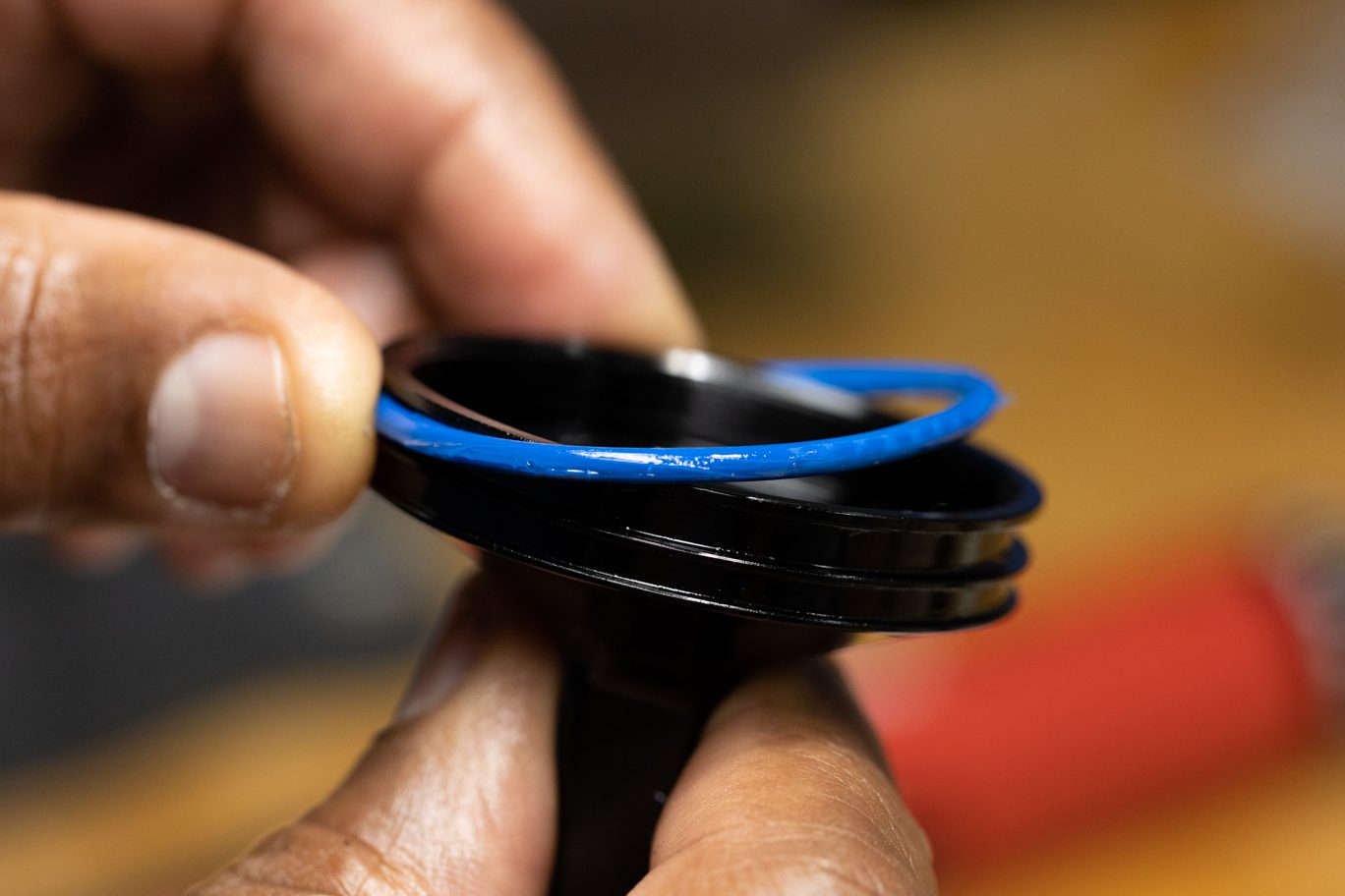
Lightly grease air seal head quad ring channel. Install new air seal head glide ring (AAD0017) into first groove on air seal head. Install new back up ring (AAD0131) below glide ring. Thoroughly grease and install new quad ring (AAD1847) behind back up ring. Lightly grease and install new external seal head o-ring (AAD1162). Install new wiper (AAD0129).
Lightly grease channel on air piston. Thoroughly grease new air piston quad ring (ADD0010). Precompress new back up L-rings (AAD0900). Install back up rings on opposite side of quad ring with openings opposite of each other on piston. Lightly grease new internal piston o-ring (AAD0138) and install on piston.
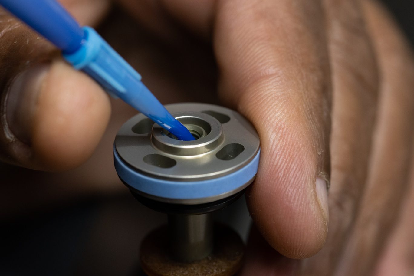
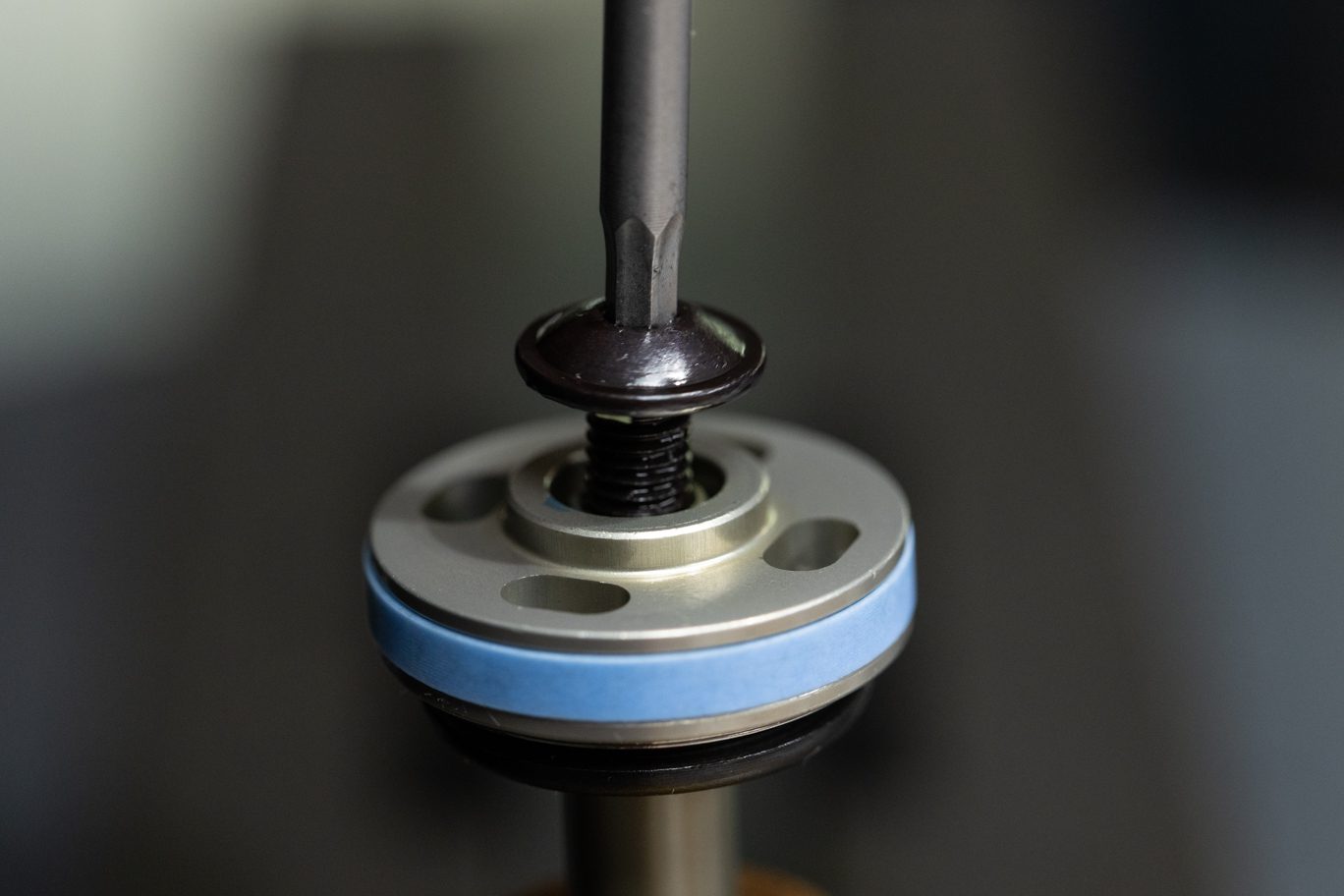
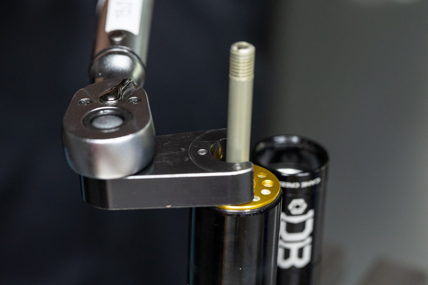
Install piston on oil seal head. Note orientation for proper installation of air piston screws. Add blue (243) Loctite to piston threads on oil seal head. Install air piston screws and torque to 4 Nm using a T20. Lightly grease quad ring on piston. Install bottom out bumper and any required stroke and/or volume reduction. Note correct orientation of large reduction spacer.
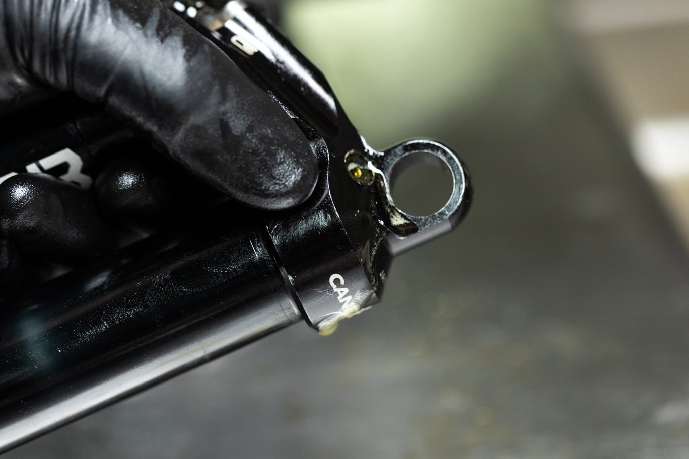
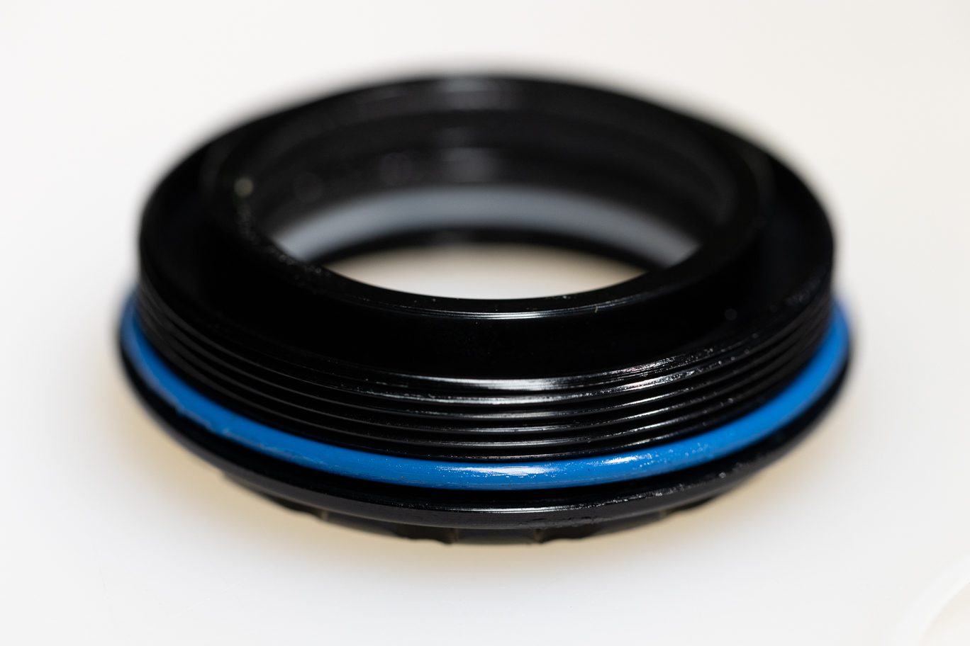
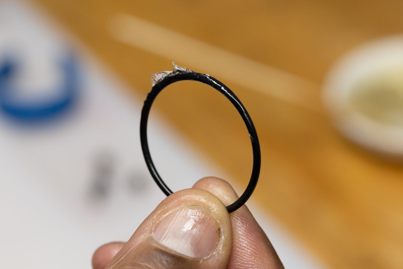
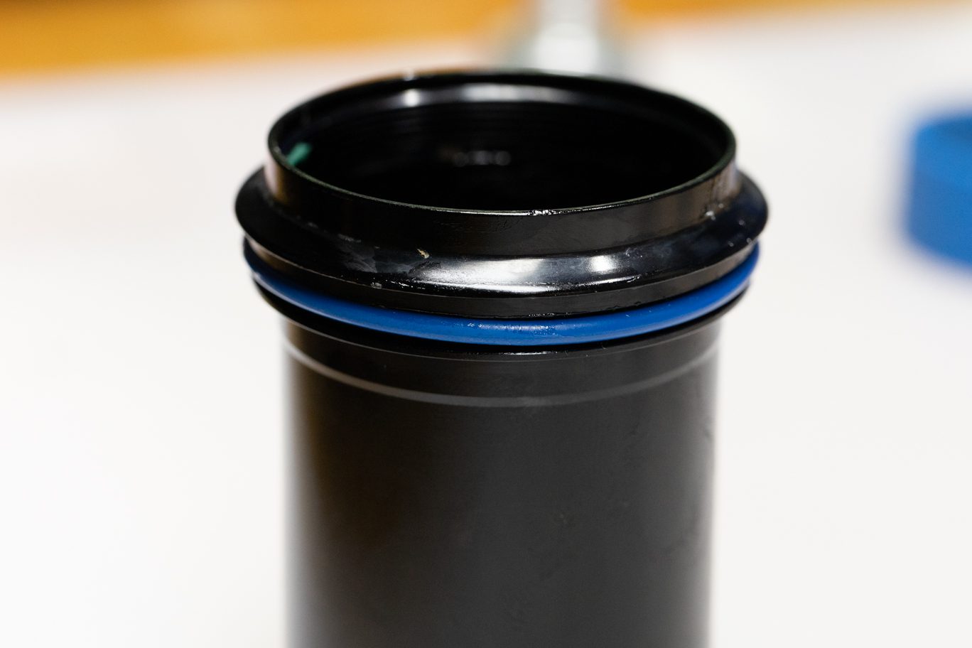
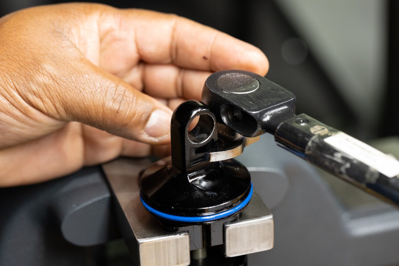
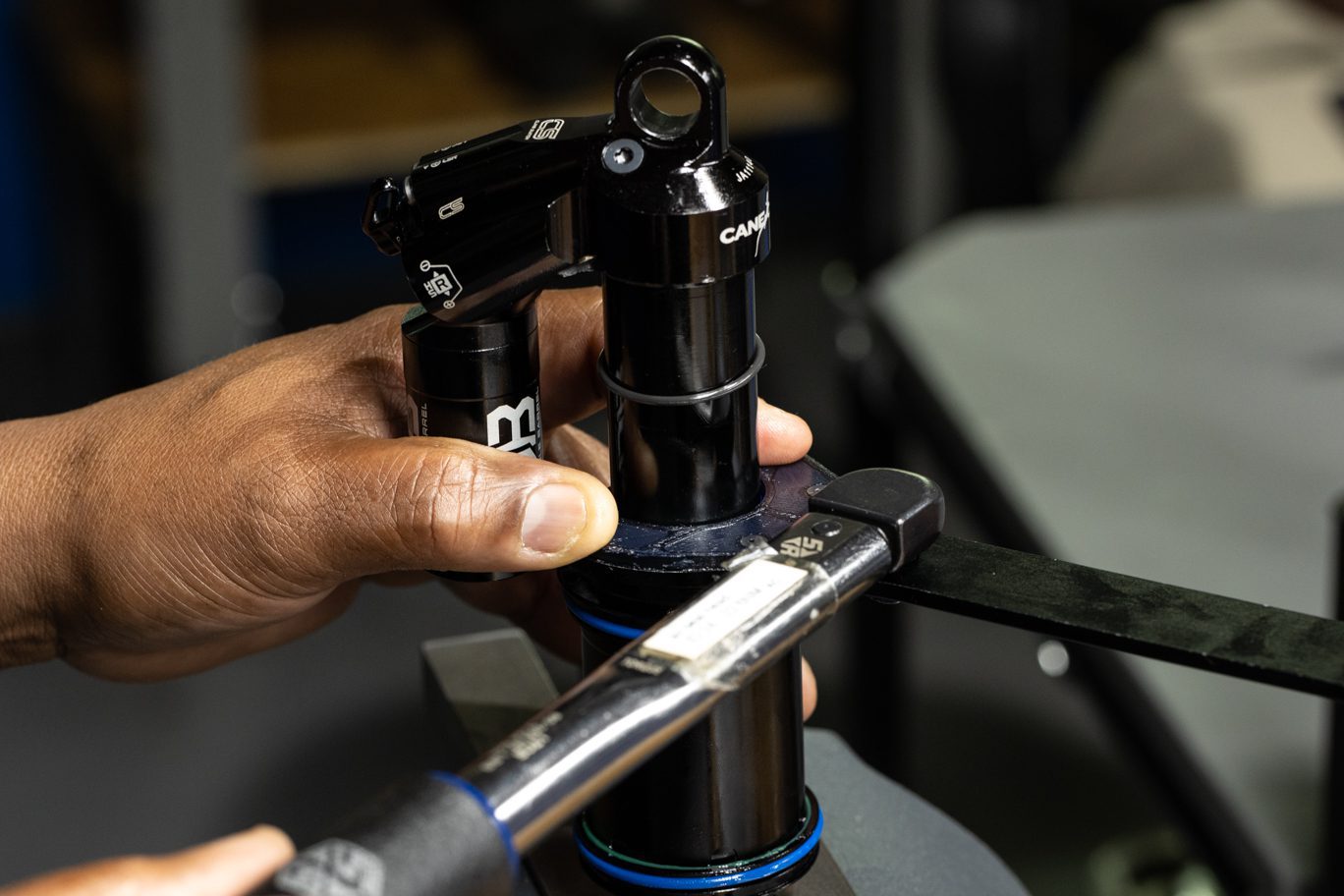
Install new end eye shim (AAD1543). Lightly grease and install new outer air can o-ring (AAD0136B) in groove on end eye. Apply blue (243) Loctite to shaft threads. Bring shaft to end eye to avoid losing end eye shim and thread end eye onto shaft. Remove any excess Loctite. Clamp shaft in vise leaving room to tighten end eye. Torque end eye to 4.8 Nm using 1/2″ crowsfoot.
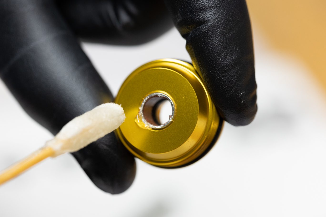
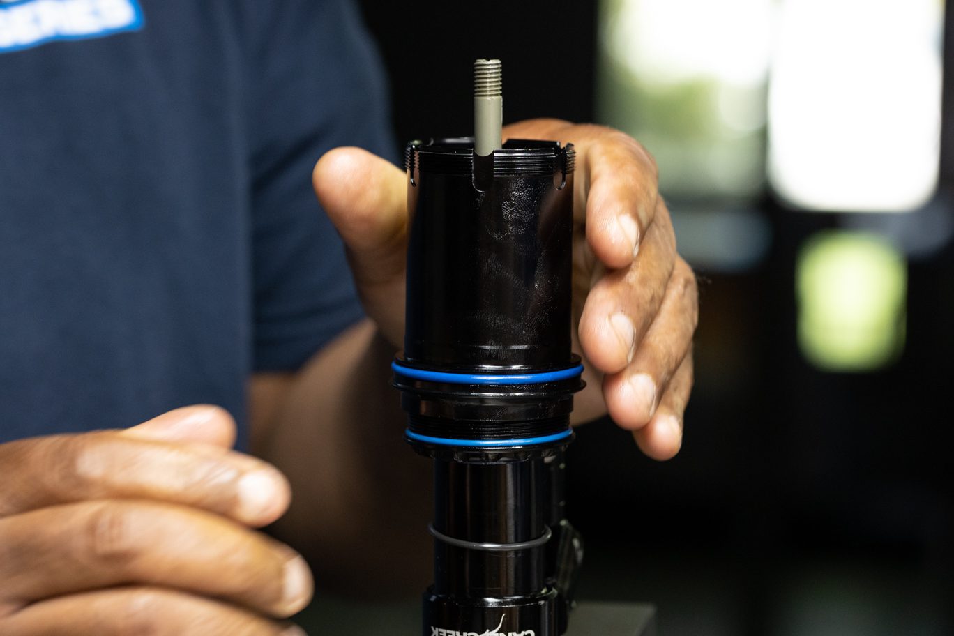
Apply Poly Lube to end eye threads on inner air can. Clamp end eye in vise. Add 8mL of Royal Purple 10w-30 to end eye. Thread inner air can onto end eye. Continue threading air seal head onto inner air can. Torque air seal head to 22.6 Nm using air seal head tool. Clean off any excess Poly Lube.
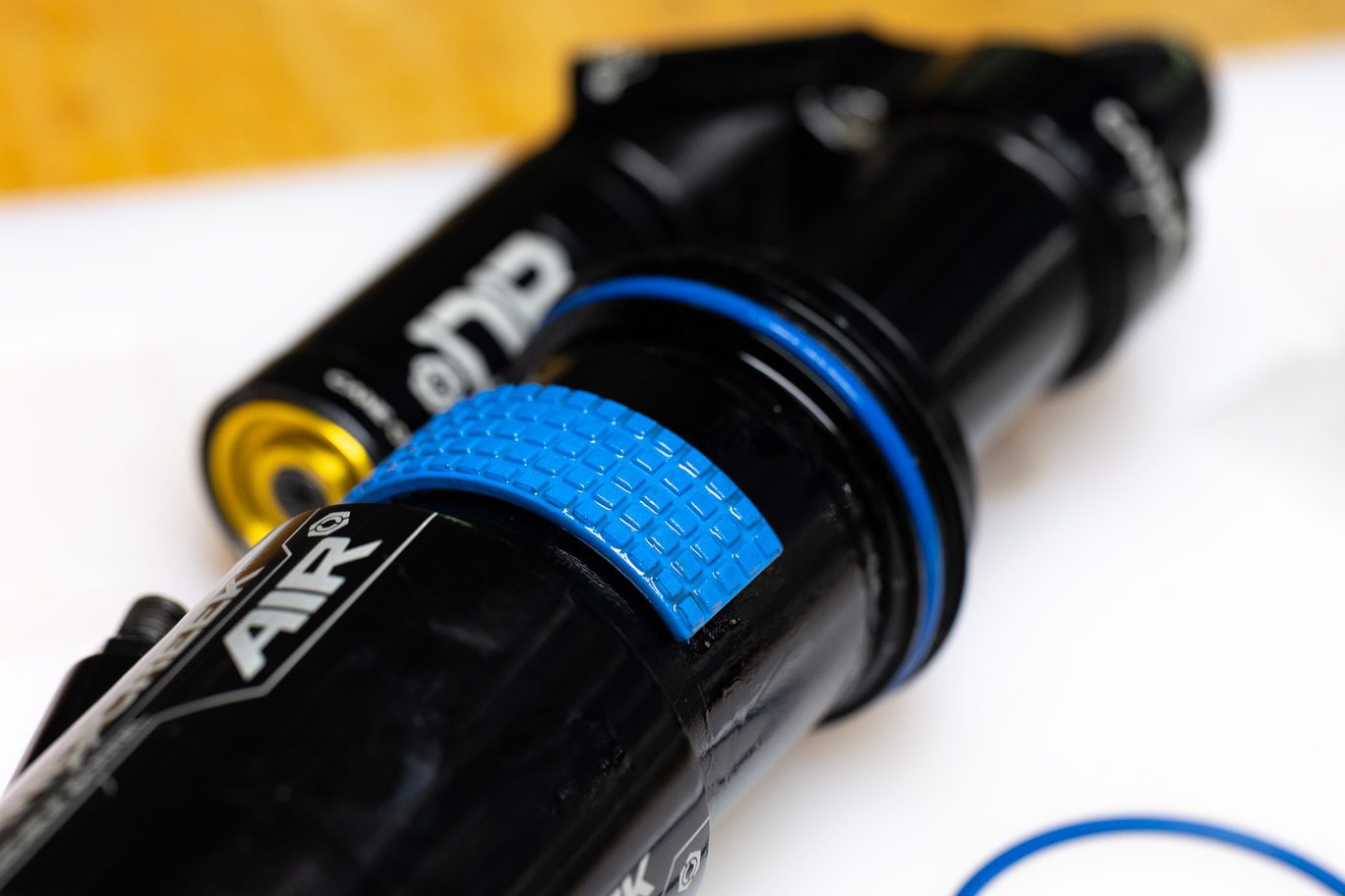
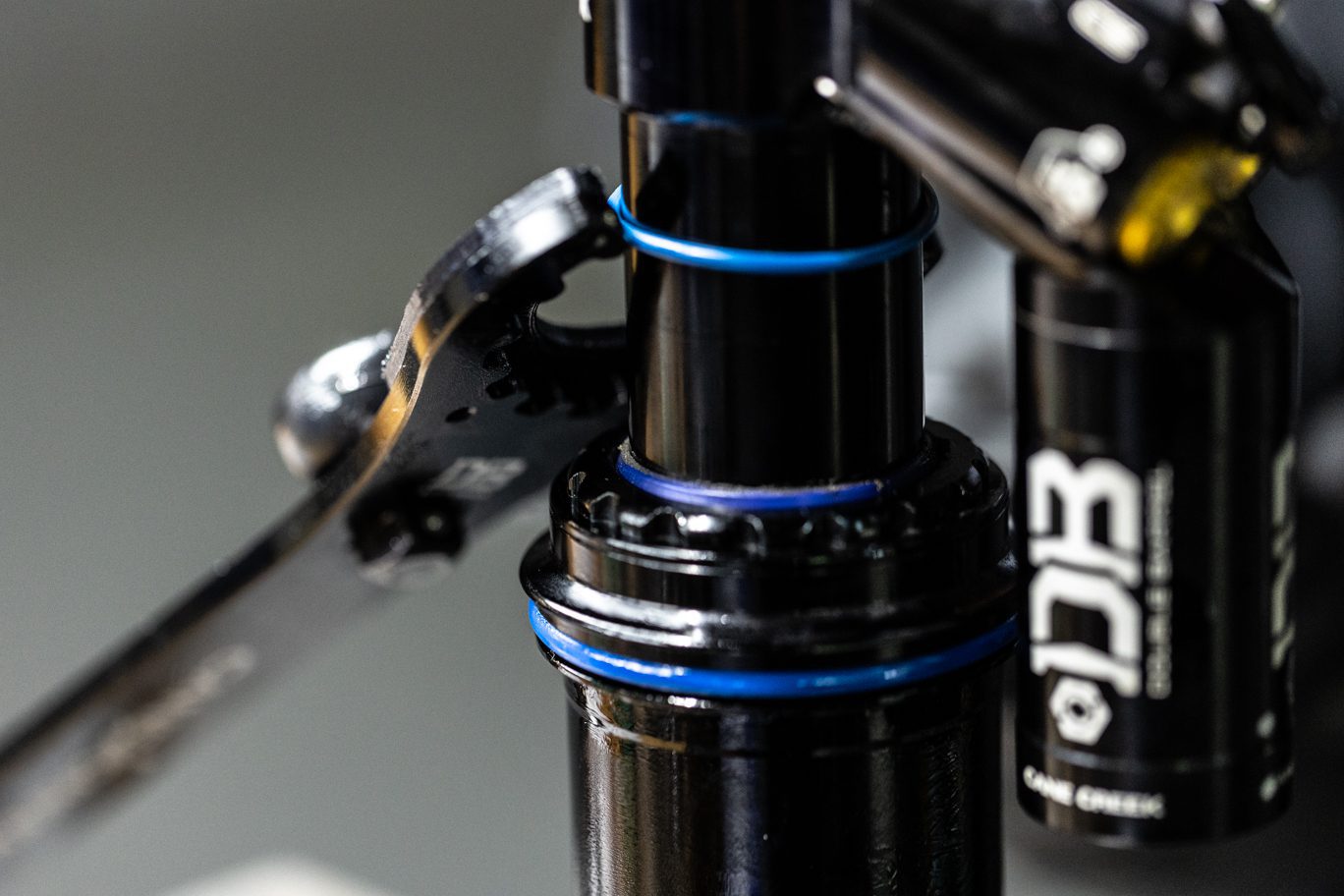
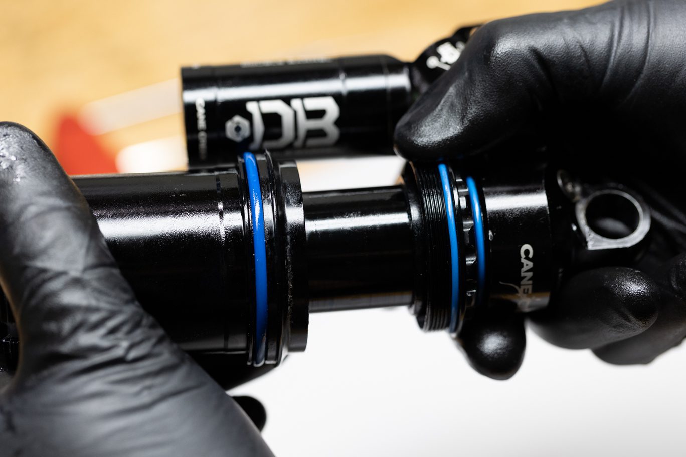
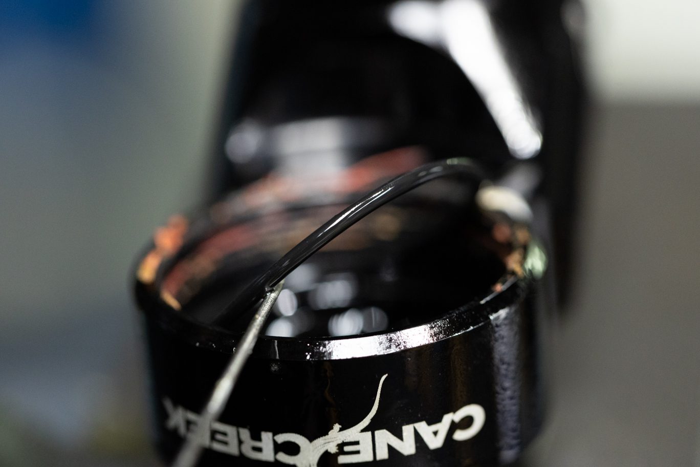
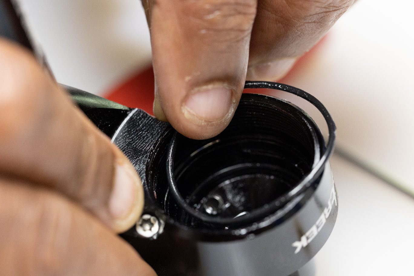
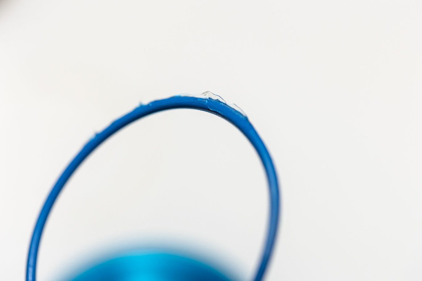
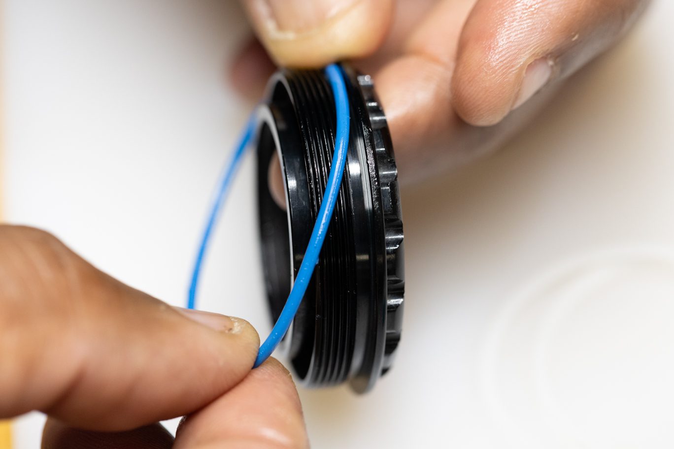
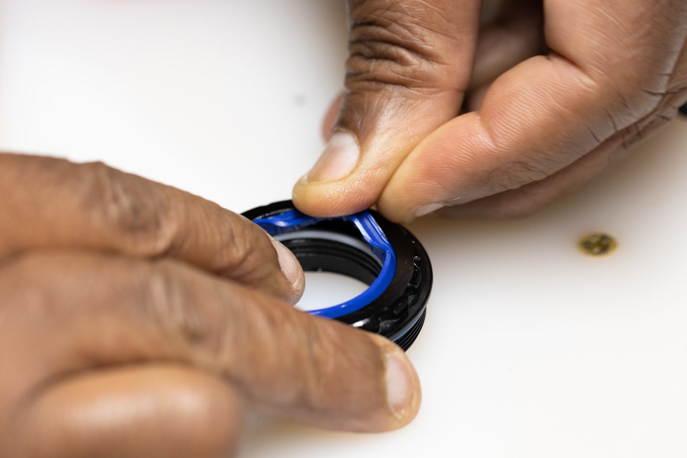
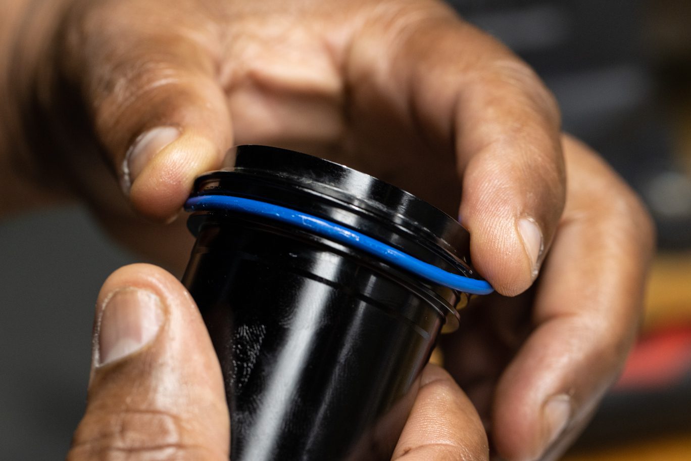
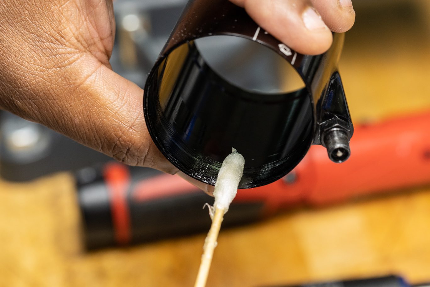
Lightly grease interior of air can on both ends. Flip shock in vise. Install outer air can onto shock working past end eye o-ring. Note air valve orientation towards cylinder head. Install any volume reduction if necessary. Install outer air can the rest of the way onto inner air can. Strap wrench can be used as needed. Install new outer air can retainer o-ring (AAD1102) on air can.

Monday: 10:00 am – 5:00 pm
Tuesday – Thursday: 10:00 am – 7:00 pm
Friday: 10:00 am – 5:00 pm
Saturday – Sunday: Closed