PayPal now available at checkout
Free US Shipping On Orders $99+
Previous slide
Next slide
Feb 2024 orig., Jun 2024 rev.
Please dispose of all waste products and materials through proper channels to avoid contamination of the environment.
Any damage or issues resulting from improper service will not be covered by warranty. If you have a shock still in its original warranty period and do not wish to void your warranty, please contact an authorized Cane Creek service center.
These service instructions cover the basic service procedures using standard service kits. If your suspension requires parts beyond standard replacement parts – shaft, damper tubes, end eyes – please consult your authorized Cane Creek service center or contact us at our Cane Creek Support Center.
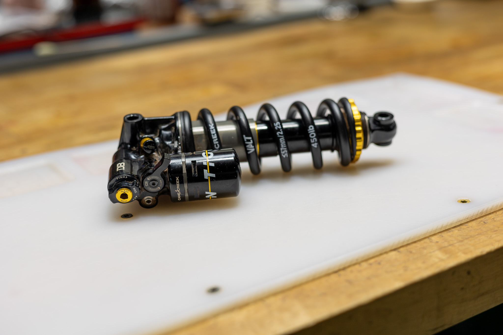
The Standard and Trunnion variants of the Tigon have identical service procedures other than where to clamp the cylinder head. Some images in these instructions may not be identical to the valve body, but process is the same for the shock in the image and the shock on your bench.
100 vs. 200 hour service
The only difference between the 100 hour service and the 200 hour service is whether to service or replace the Oil Seal Head. At 100 hours, the Seal Head should be cleaned, serviced and reinstalled. At 200 hours, it should be replaced. If uncertain on hours, check for wear on the dual bushings inside the Seal Head. When in doubt, replace.
BDD0341– Tigon Complete 100 Hour Rebuilt Kit
OR
BDD0343– Tigon Complete 200 Hour Rebuilt Kit
BDD0320 – Tigon Oil Seal Head Pin Spanner
ADD0327 – Tigon Shaft Seal Head Bullet
ADD0328 – Tigon IFP Service Plug
AAD1361-01 – DBCoil/ DBAir – Oil Fill Needle Adapter
DBT016 – DB Gas Fill Needle
Shaft Clamp – 12.7mm (1/2″)
Allen wrench – 4mm
Torx wrench – T20
Crowfoot wrenches – 12 & 34mm
Open end wrench – 19mm
Torque wrenches
Knipex pliers
Pick – metal & plastic
Strap wrench
M8 x 1.25 bolt, min. 45mm length
Suspension Grease
Motorex 4wt Racing Fork Oil
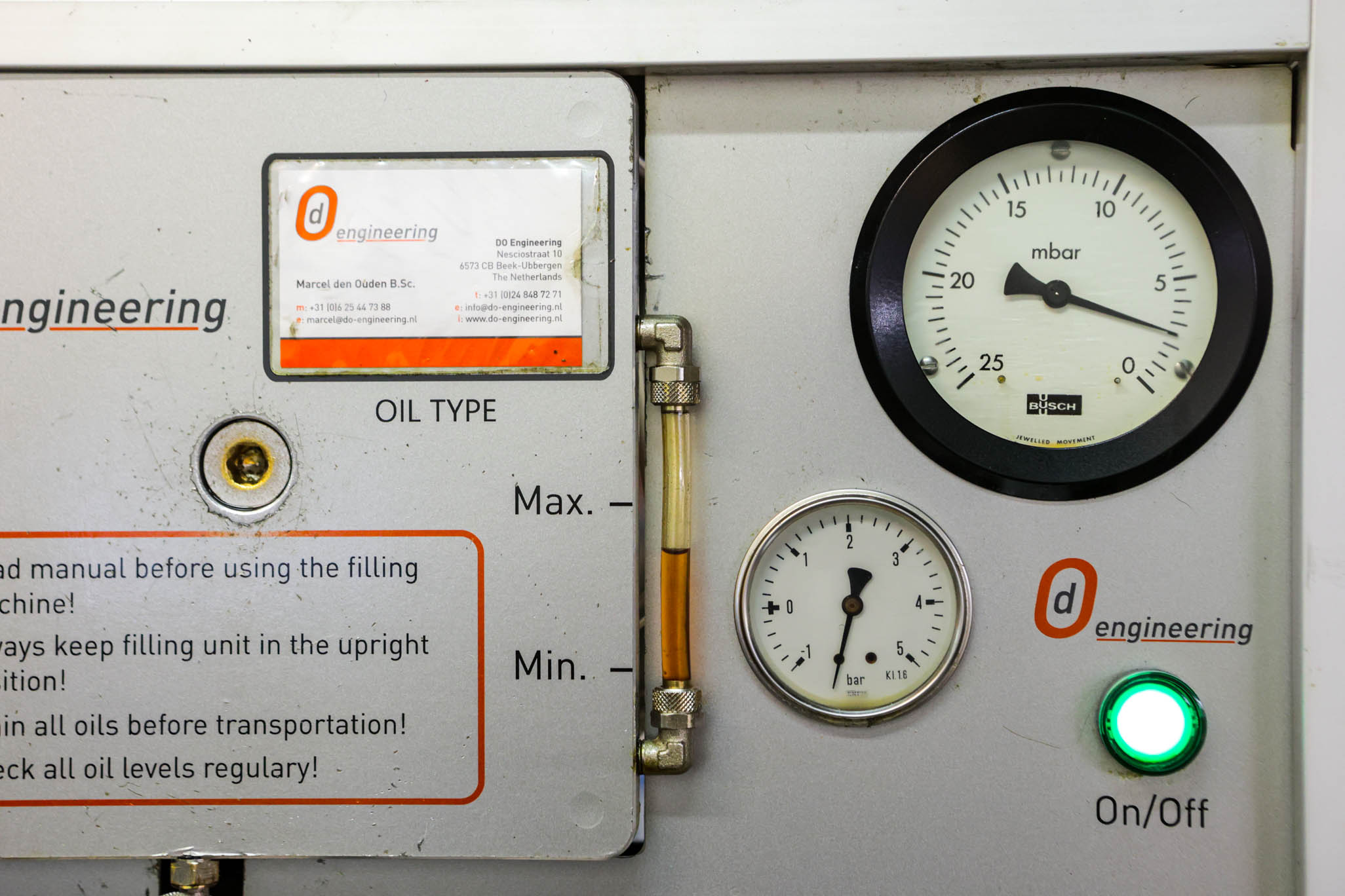
Vacuum Oil Fill Machine
Nitrogen Fill System
Torque & Loctite Chart
| Part | Torque Spec | Loctite Spec |
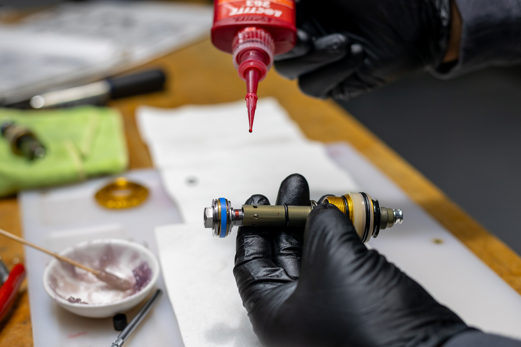
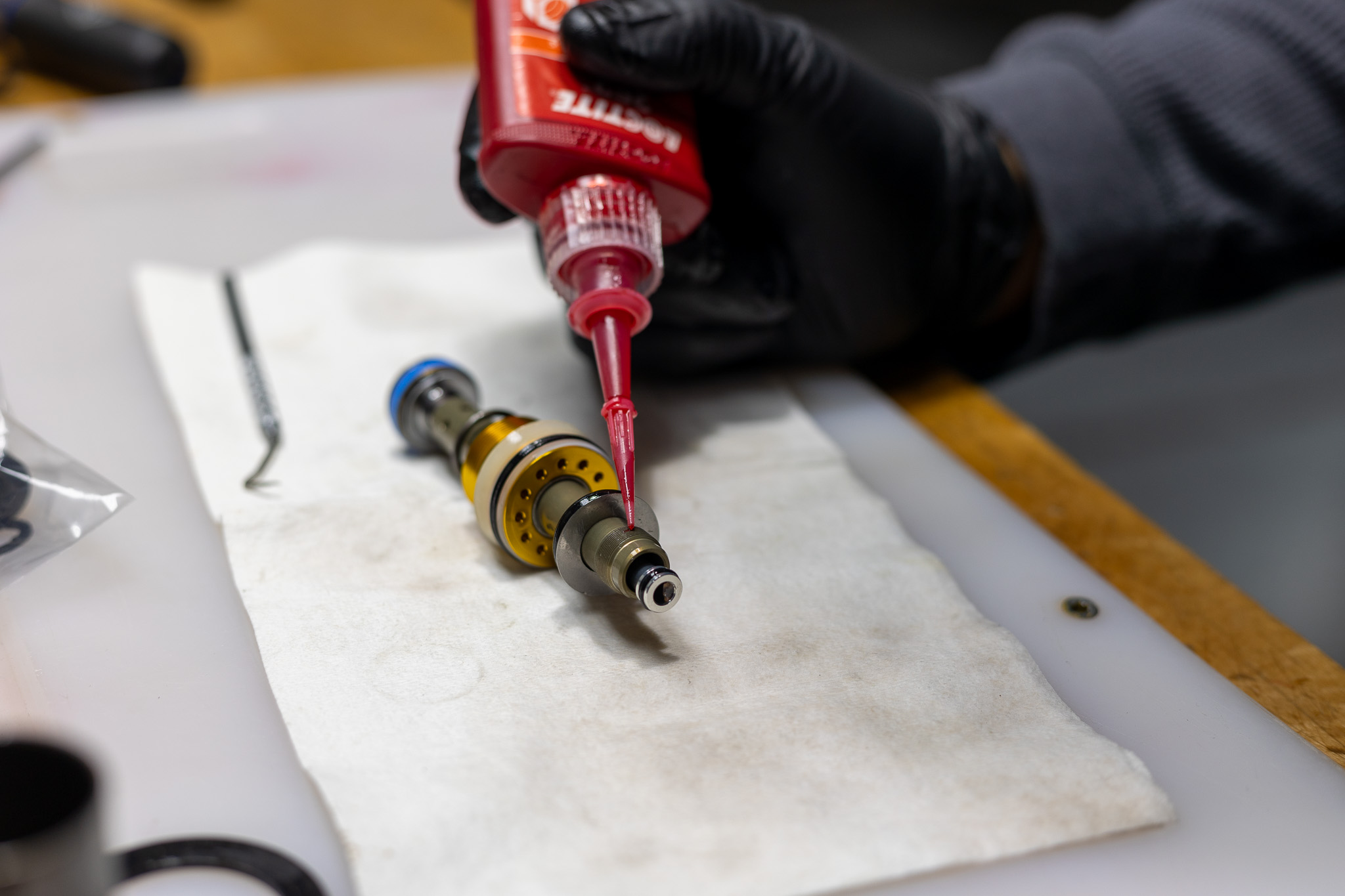
| Inner Shaft to Outer Shaft | none | 263 (Red) |
| Shaft Assembly to Valve Body | 10 Nm | 263 (Red) |
| Oil Seal Head | 30 Nm | none |
| RAMP Tube | 14.5 Nm | none |
Oil Chart
| Oil Location | Oil Type | Oil Amount |
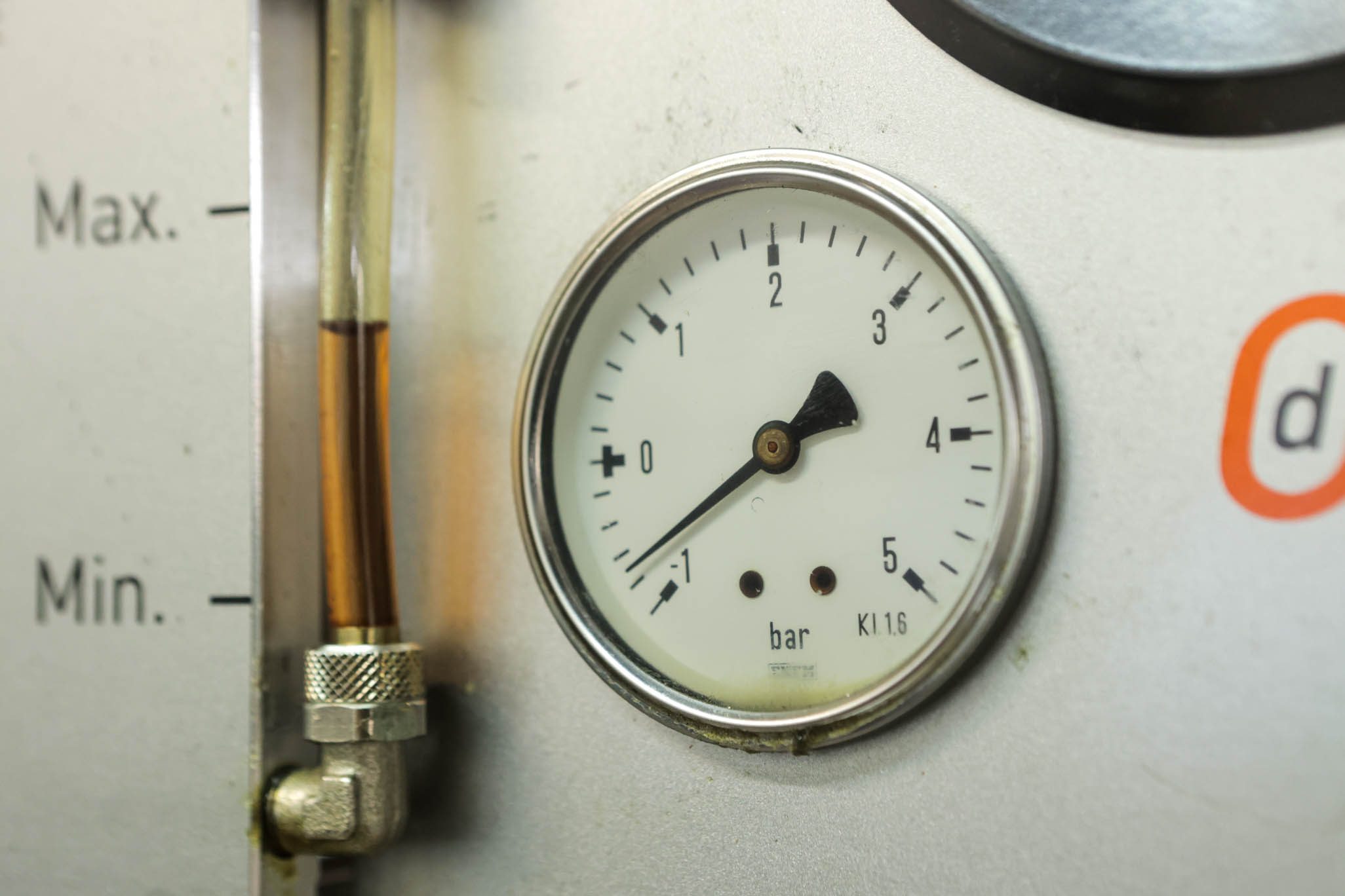
| Damper Fill | Motorex 4wt Racing Fork Oil | Fill to 3 Bars |
Nitrogen Chart
| Nitrogen Location | Nitrogen Pressure |
| Valve Body | 11-12 Bars |
No TSBs exist for Tigon.
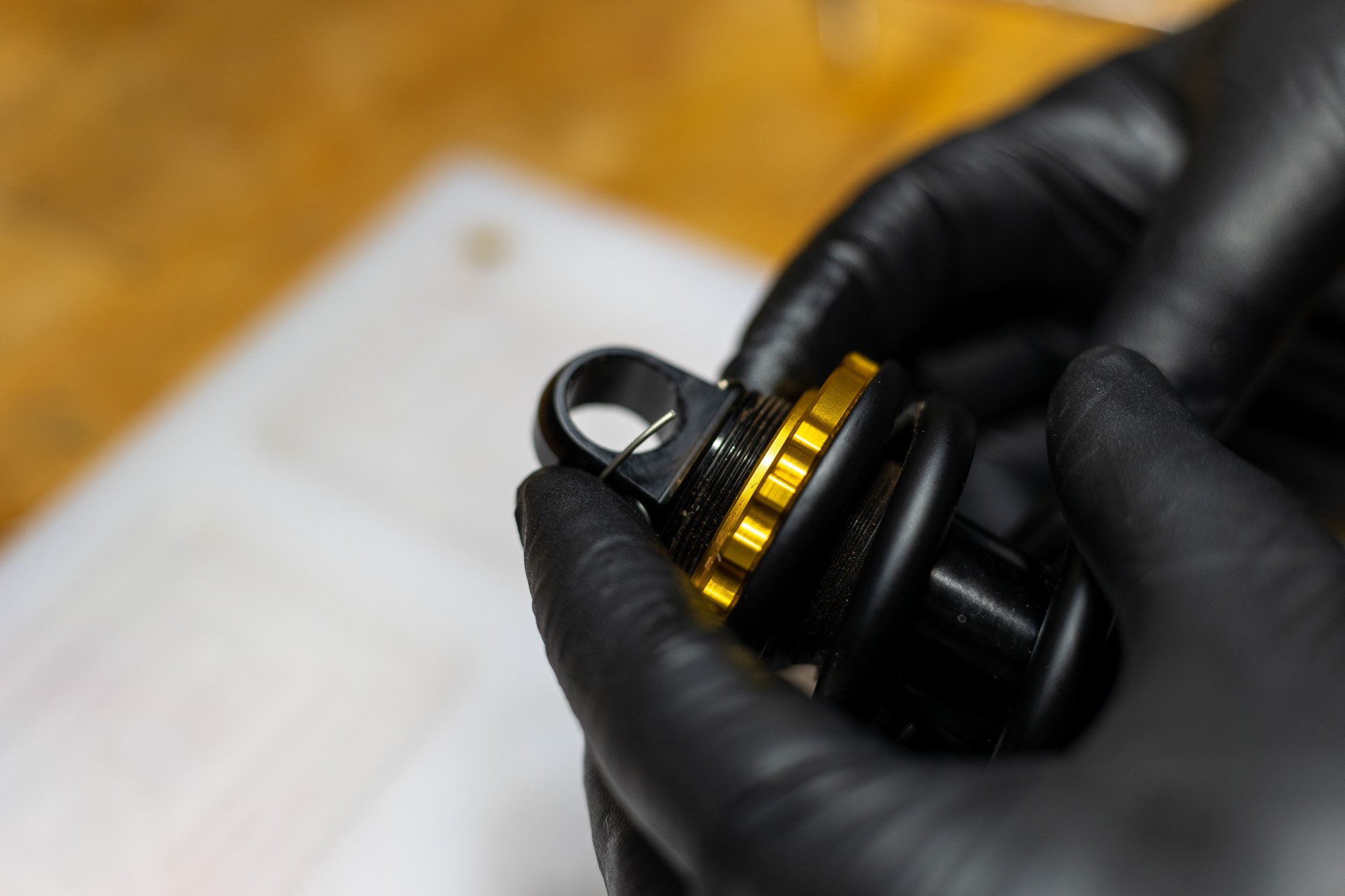
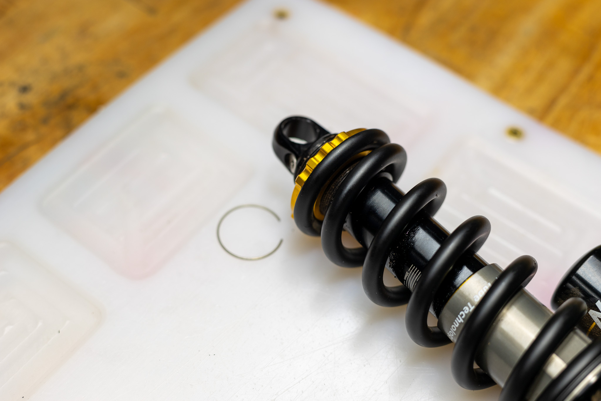
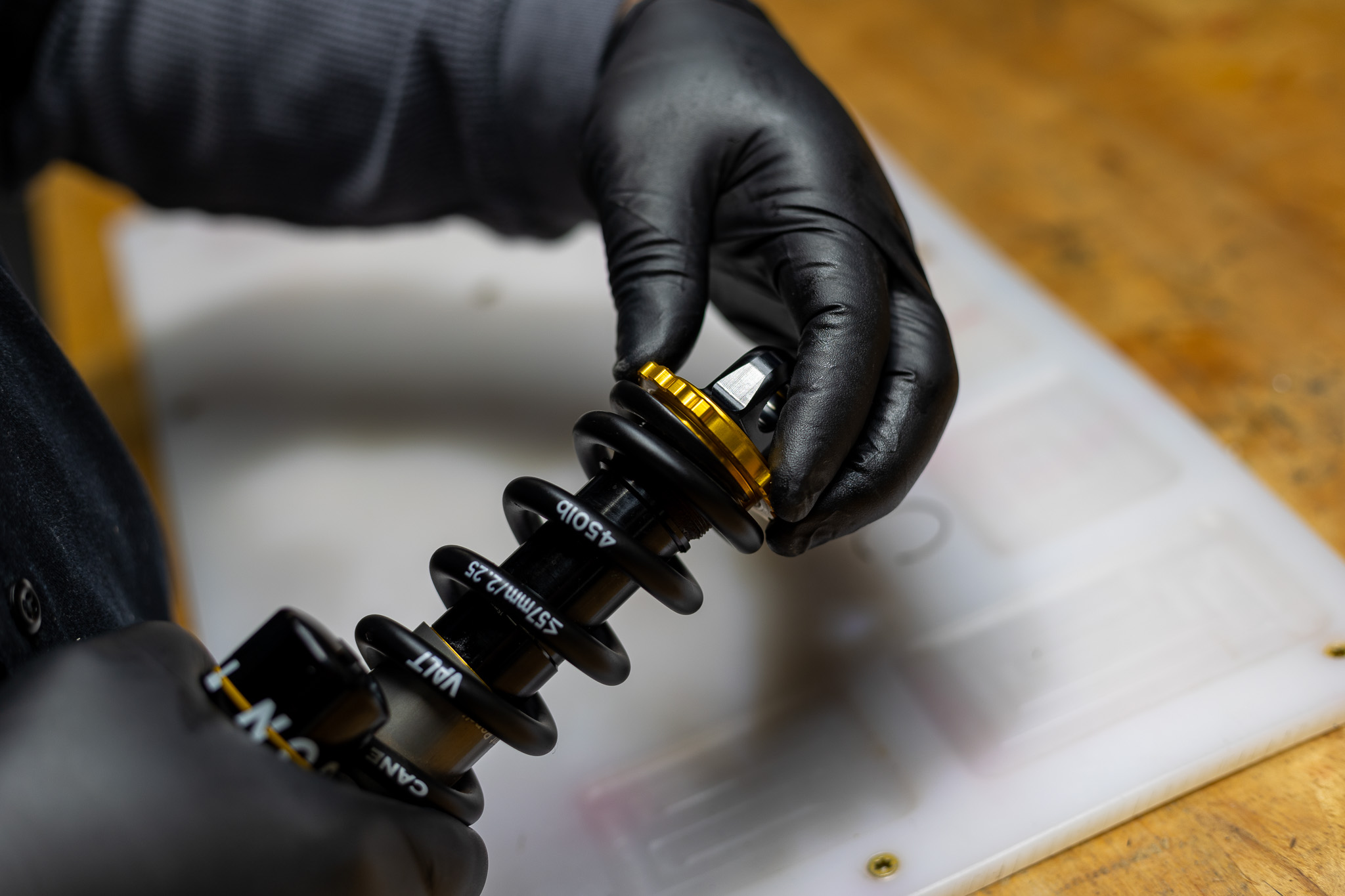
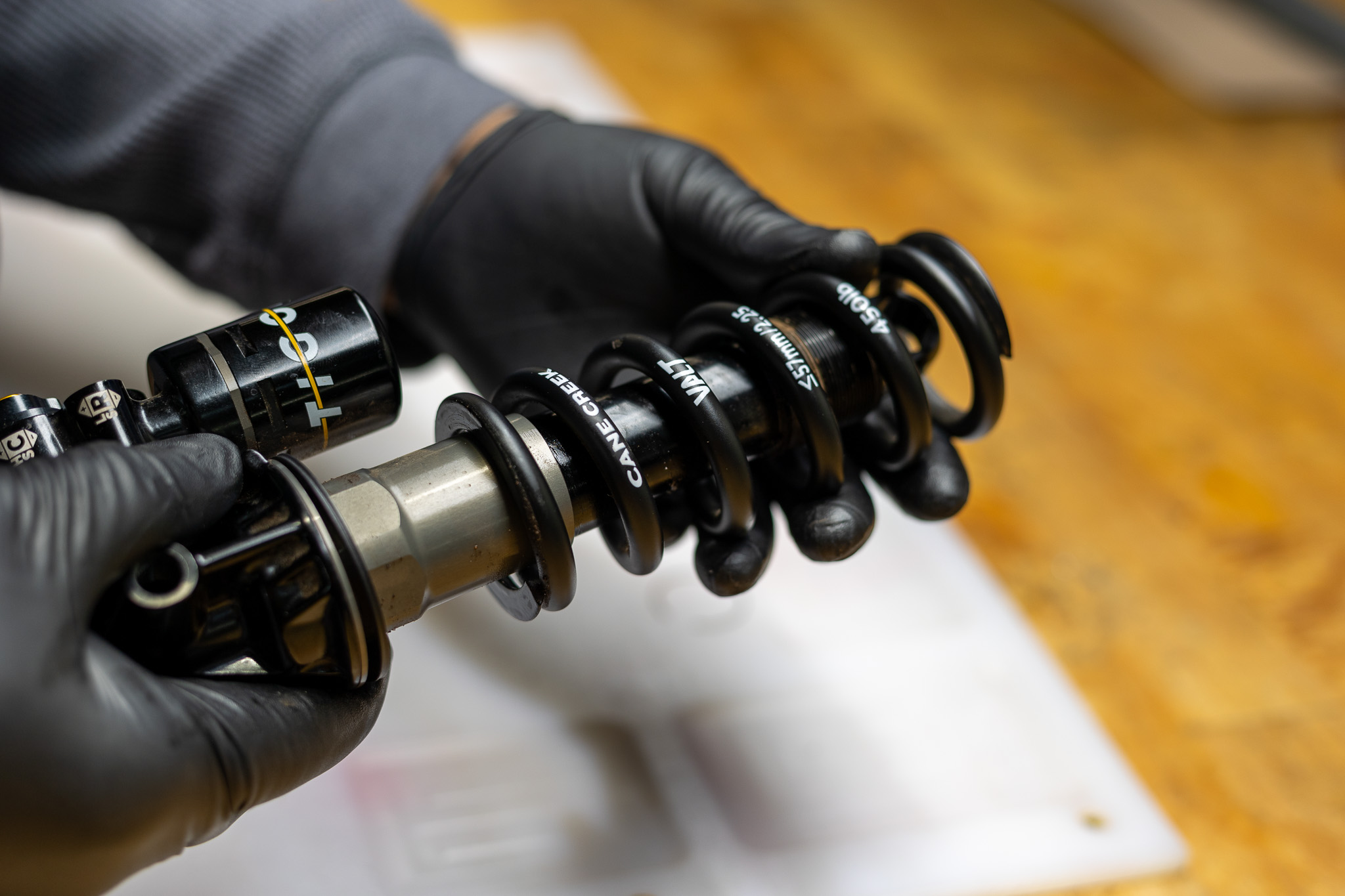
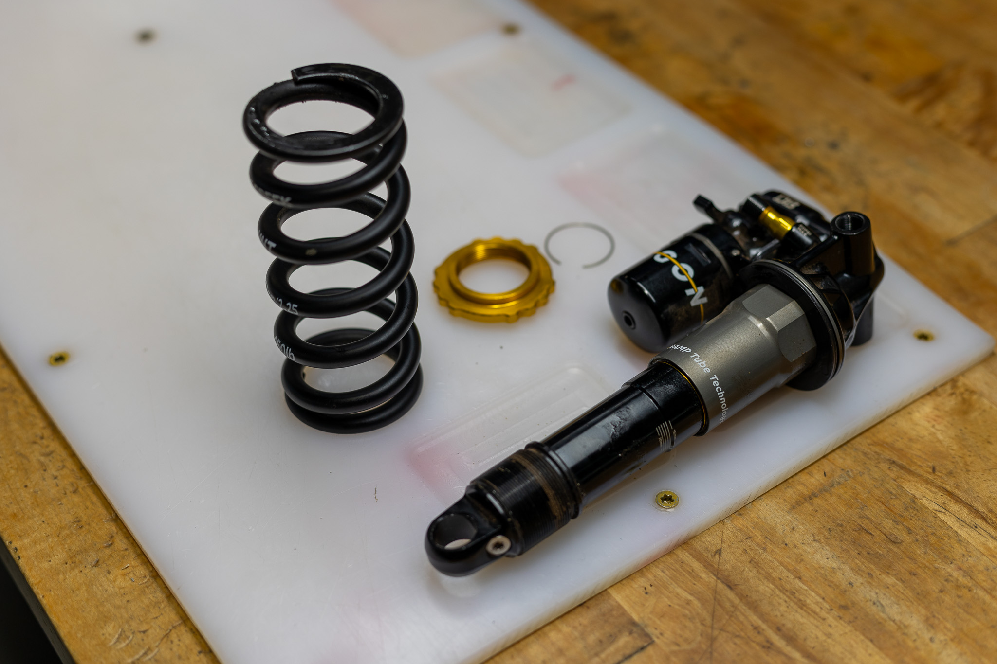
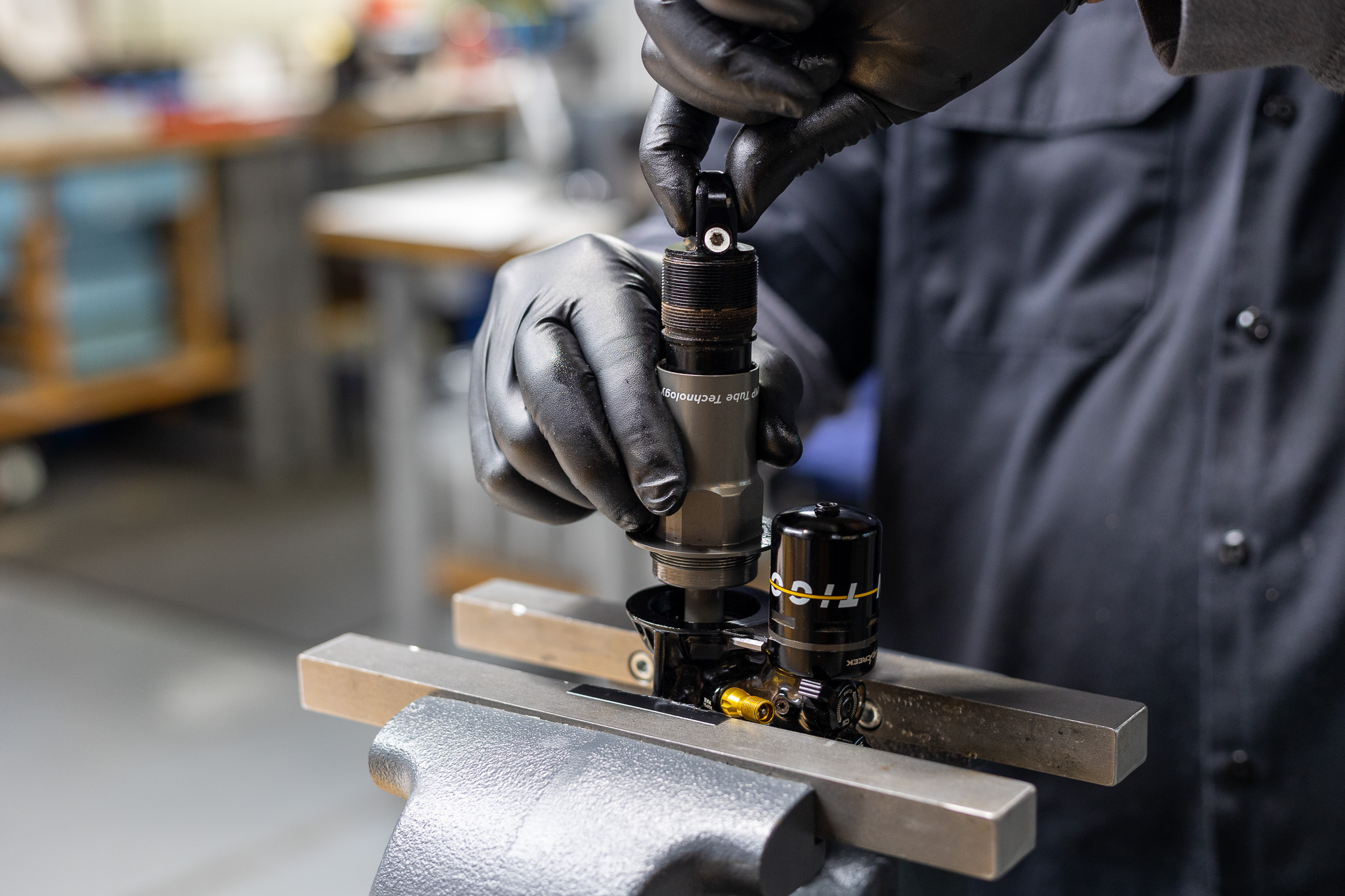
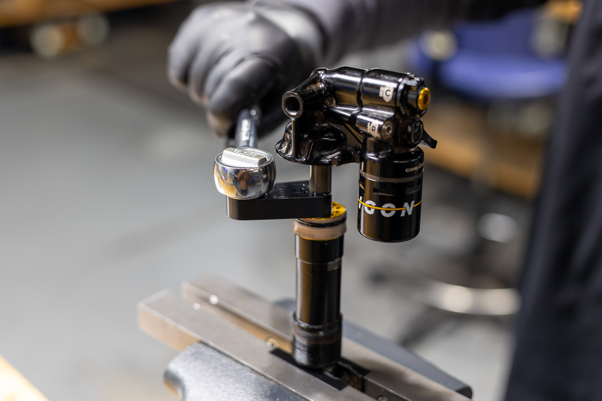
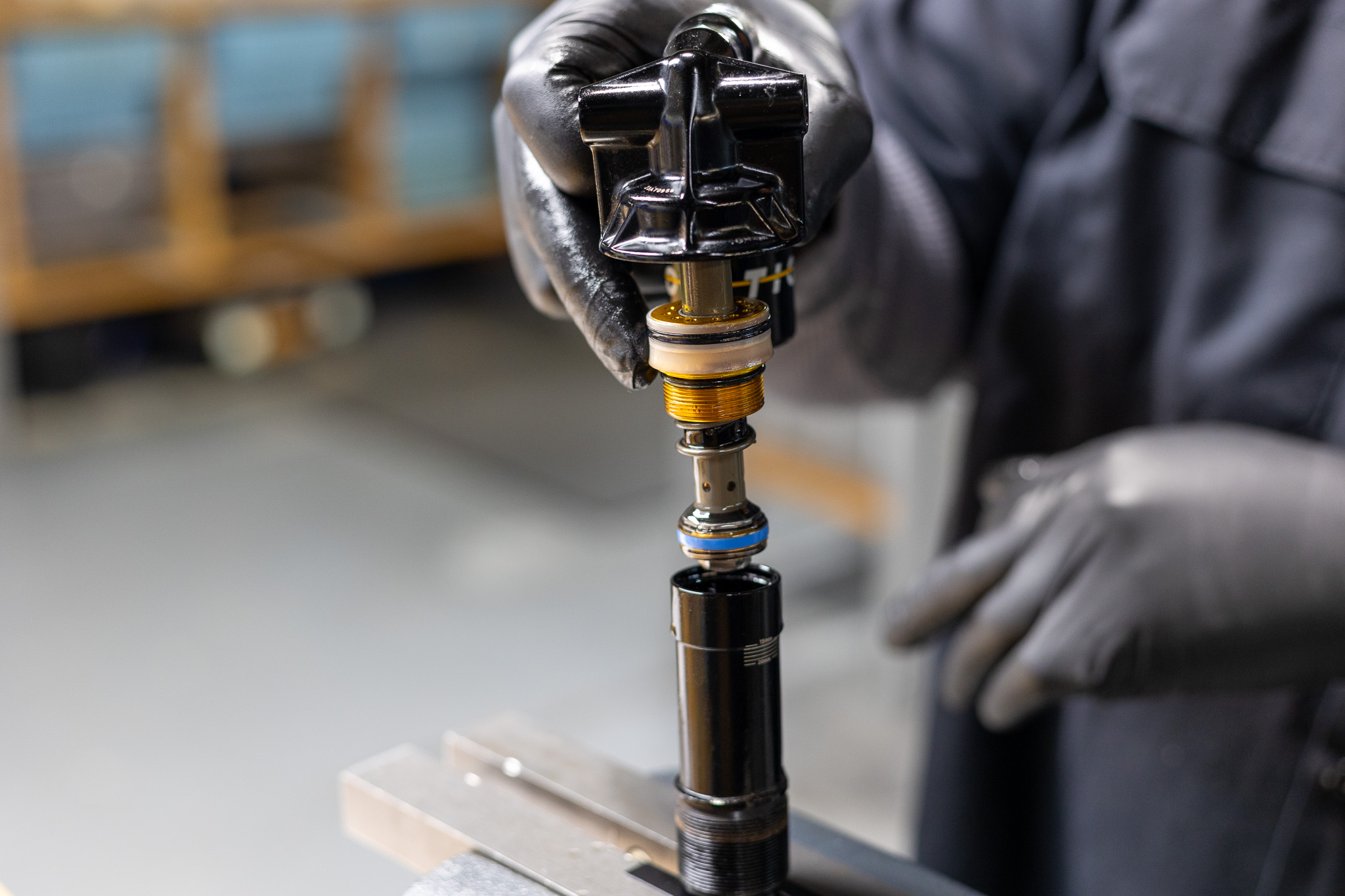
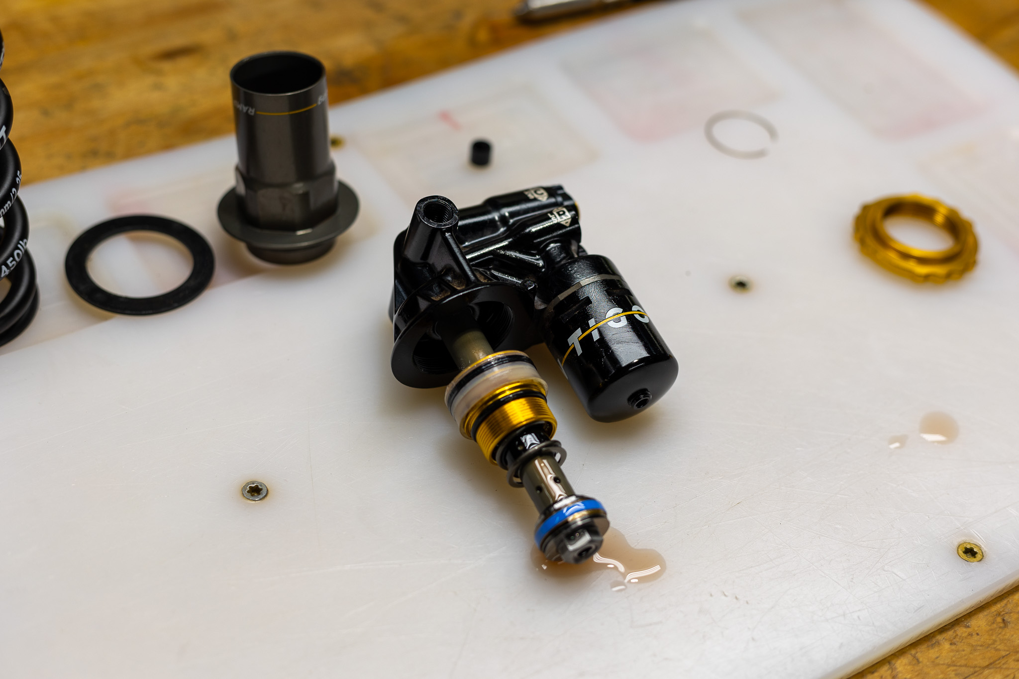
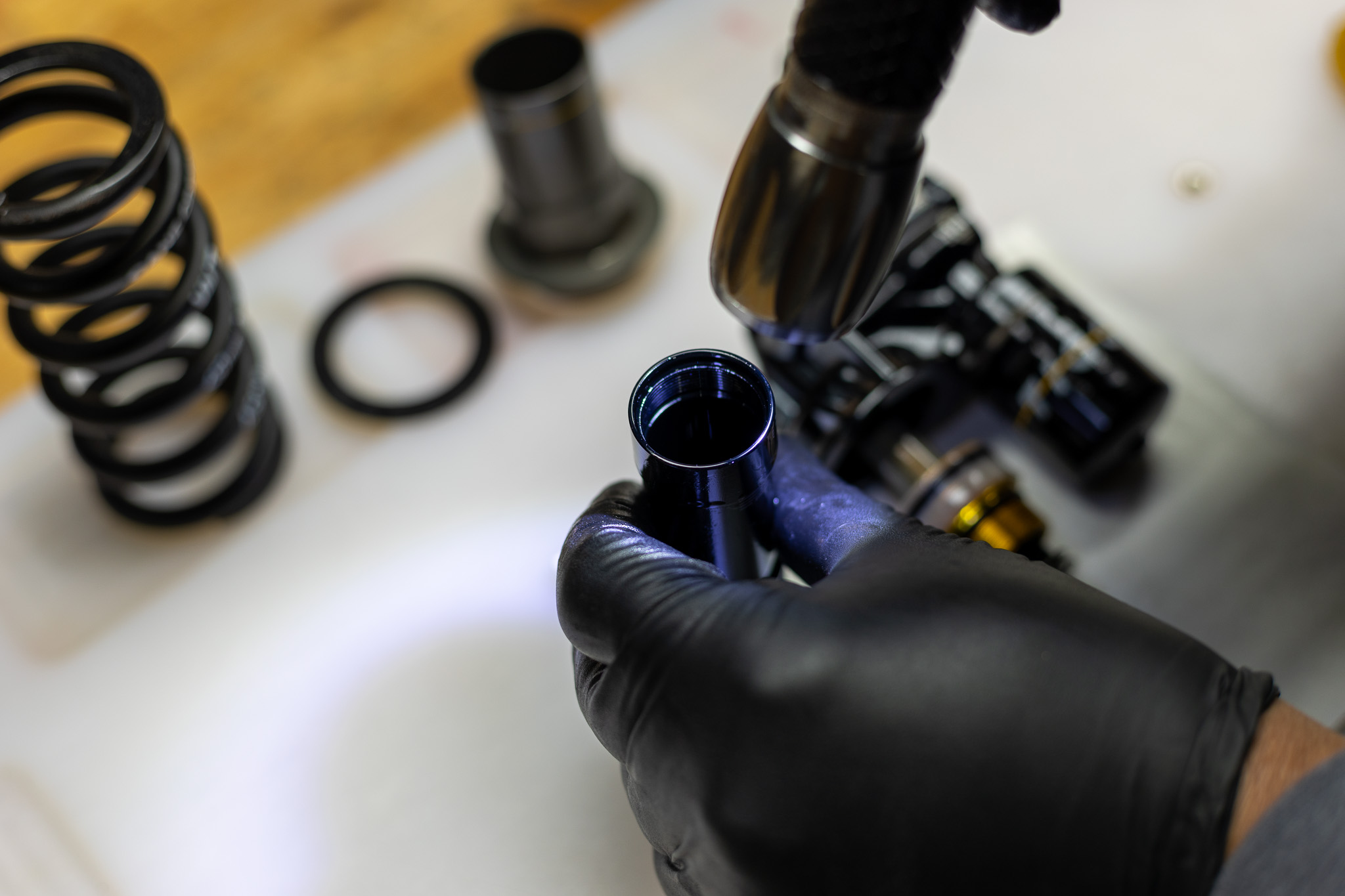
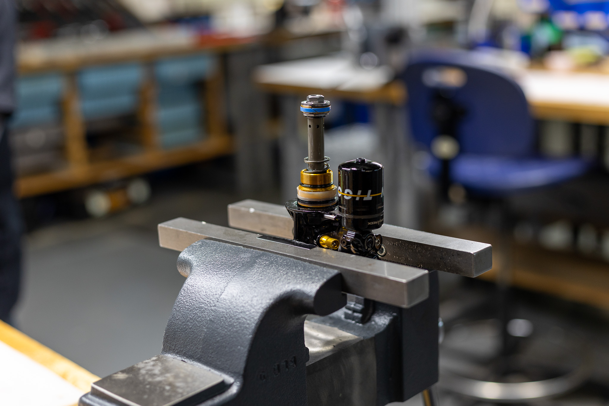
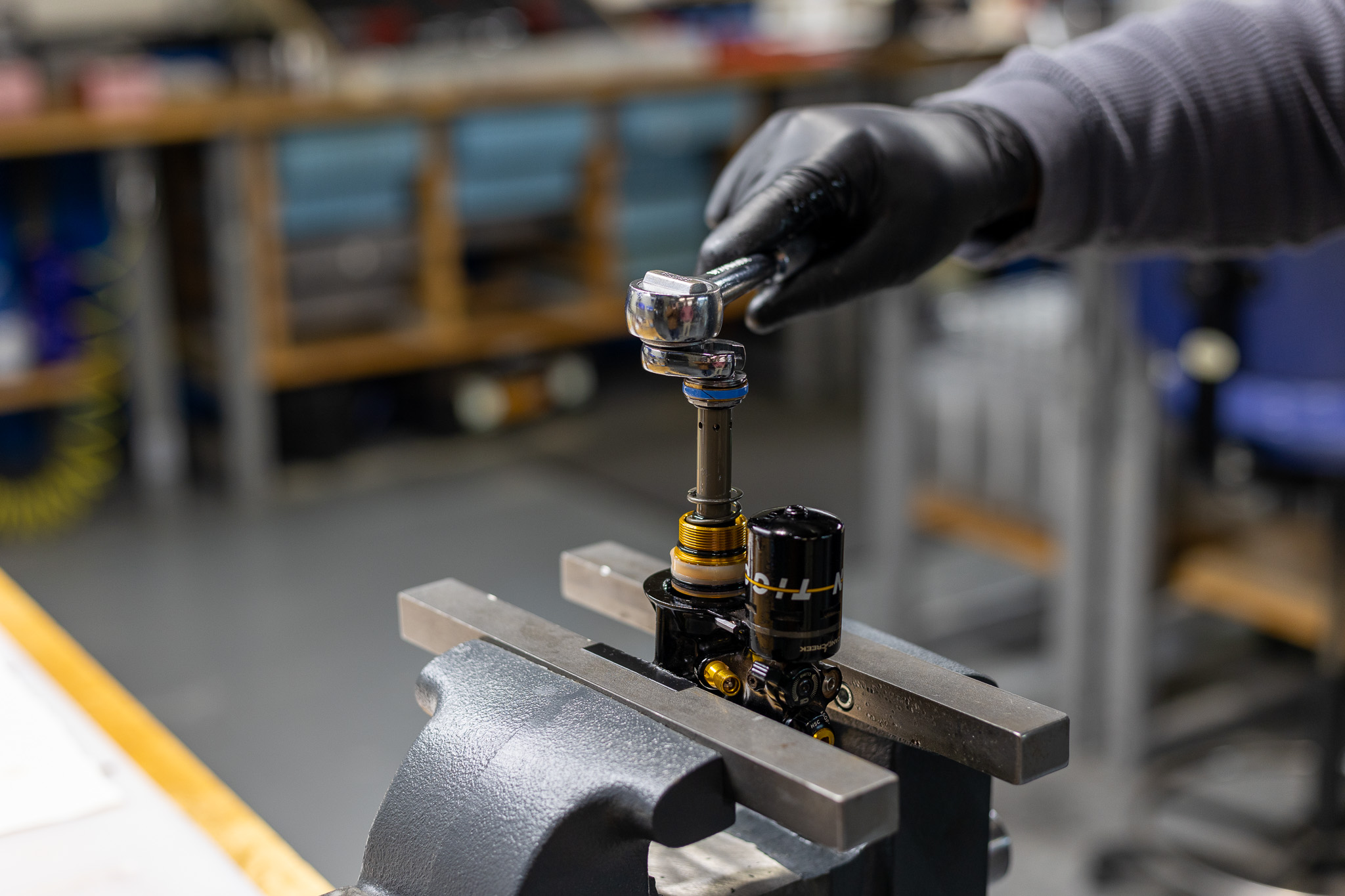
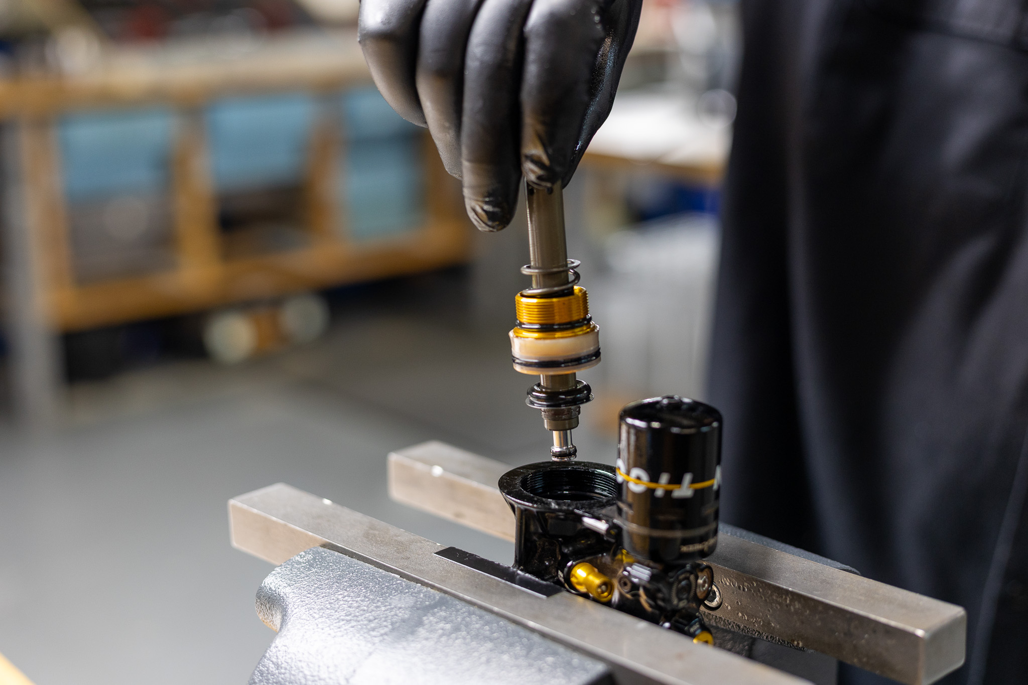
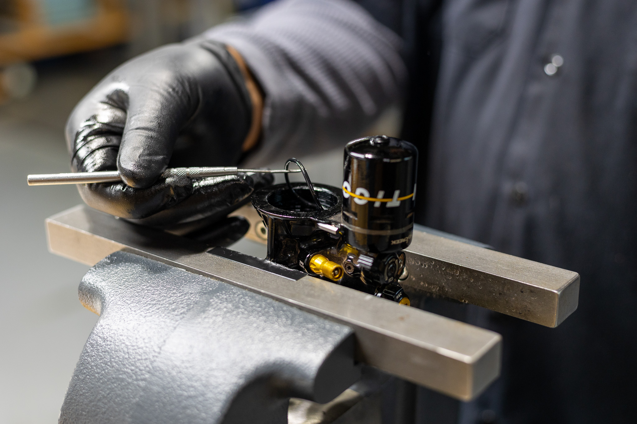
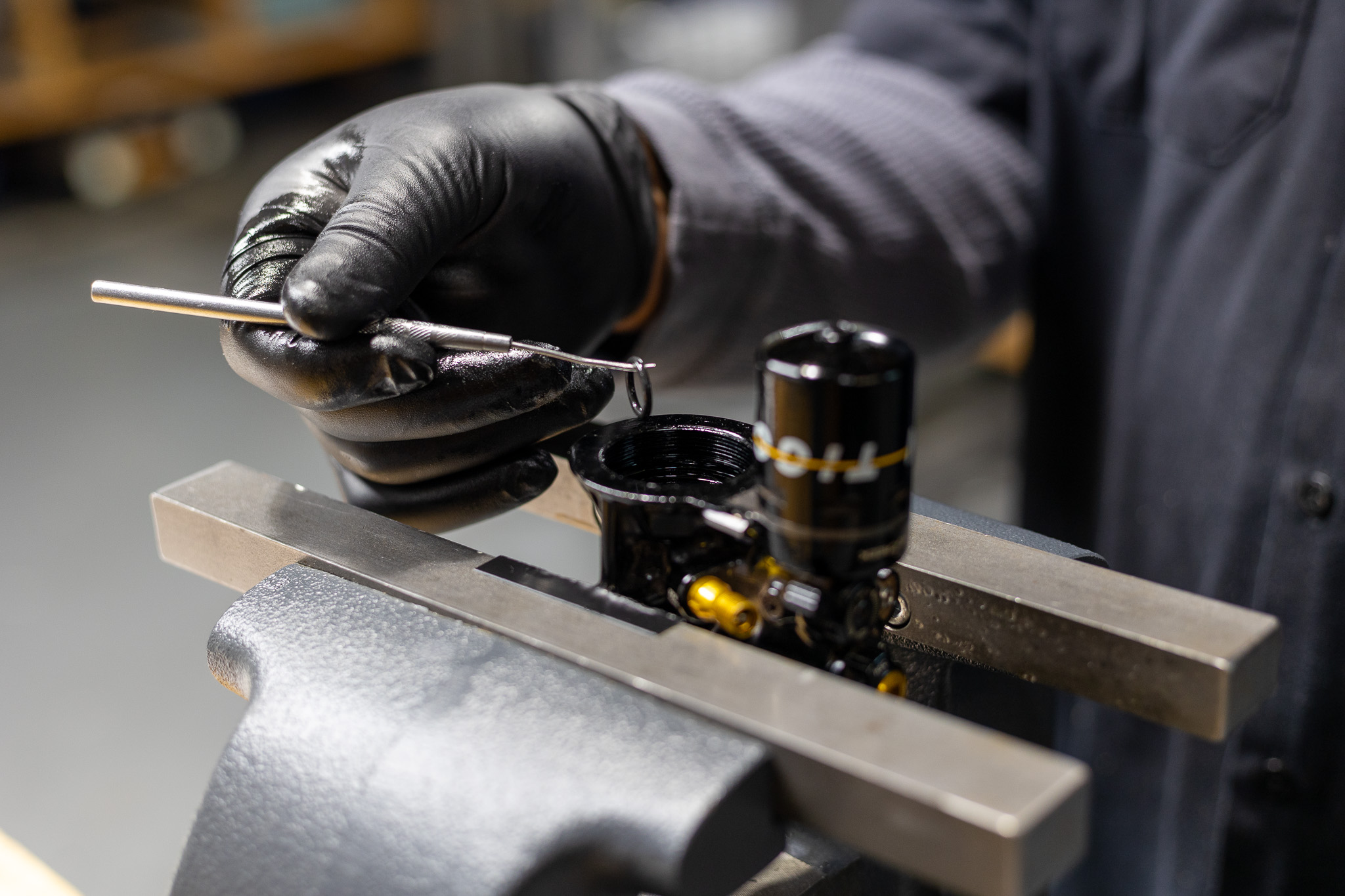
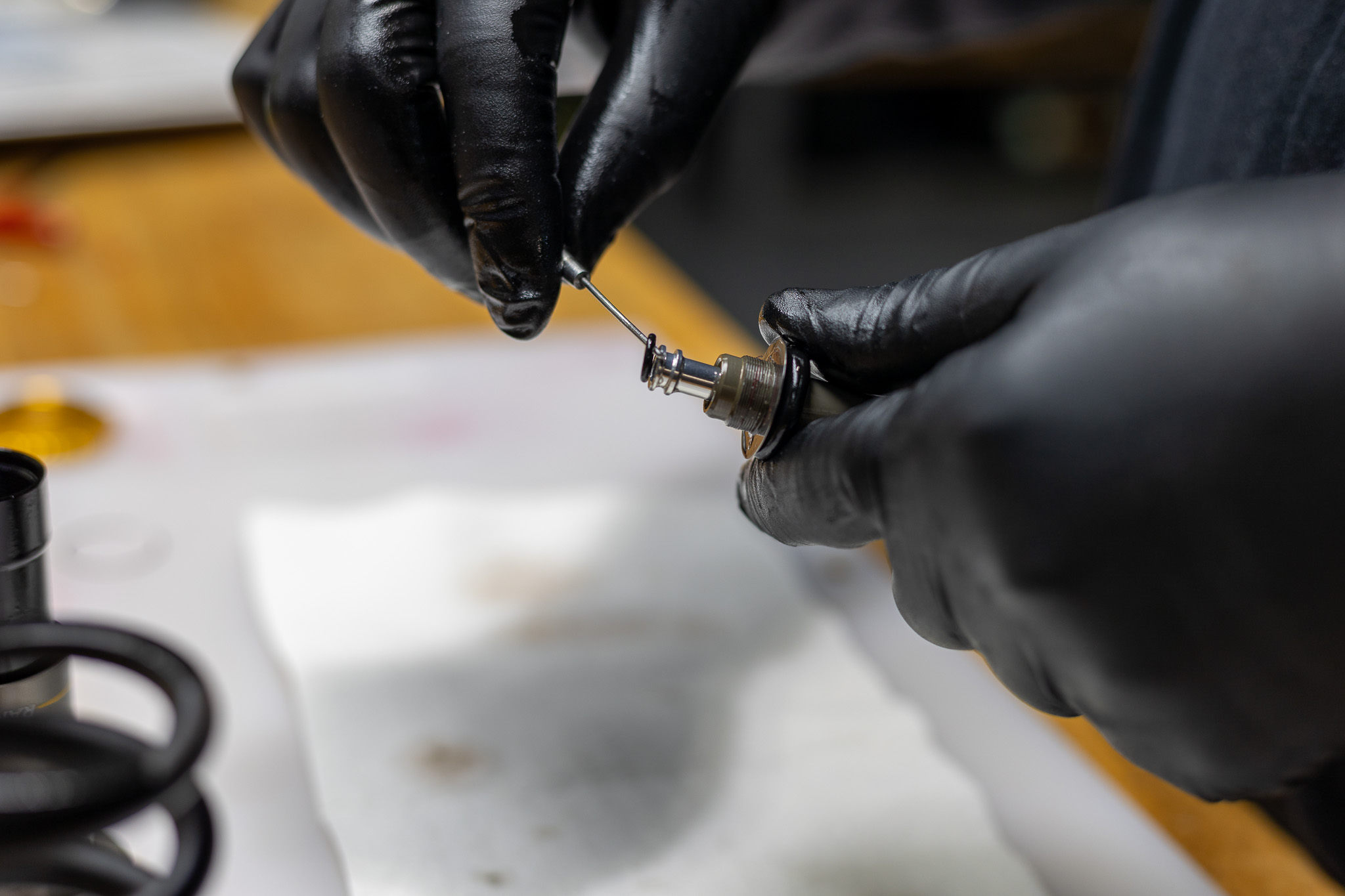
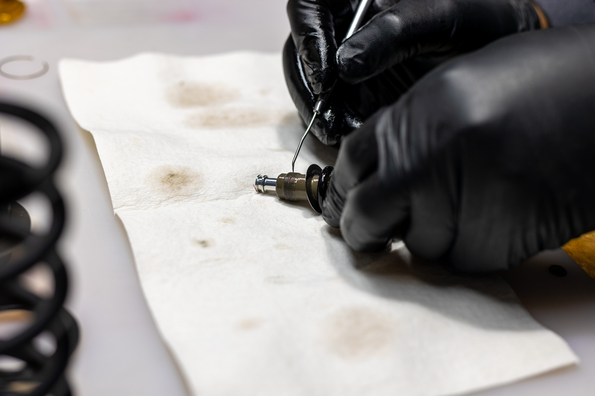
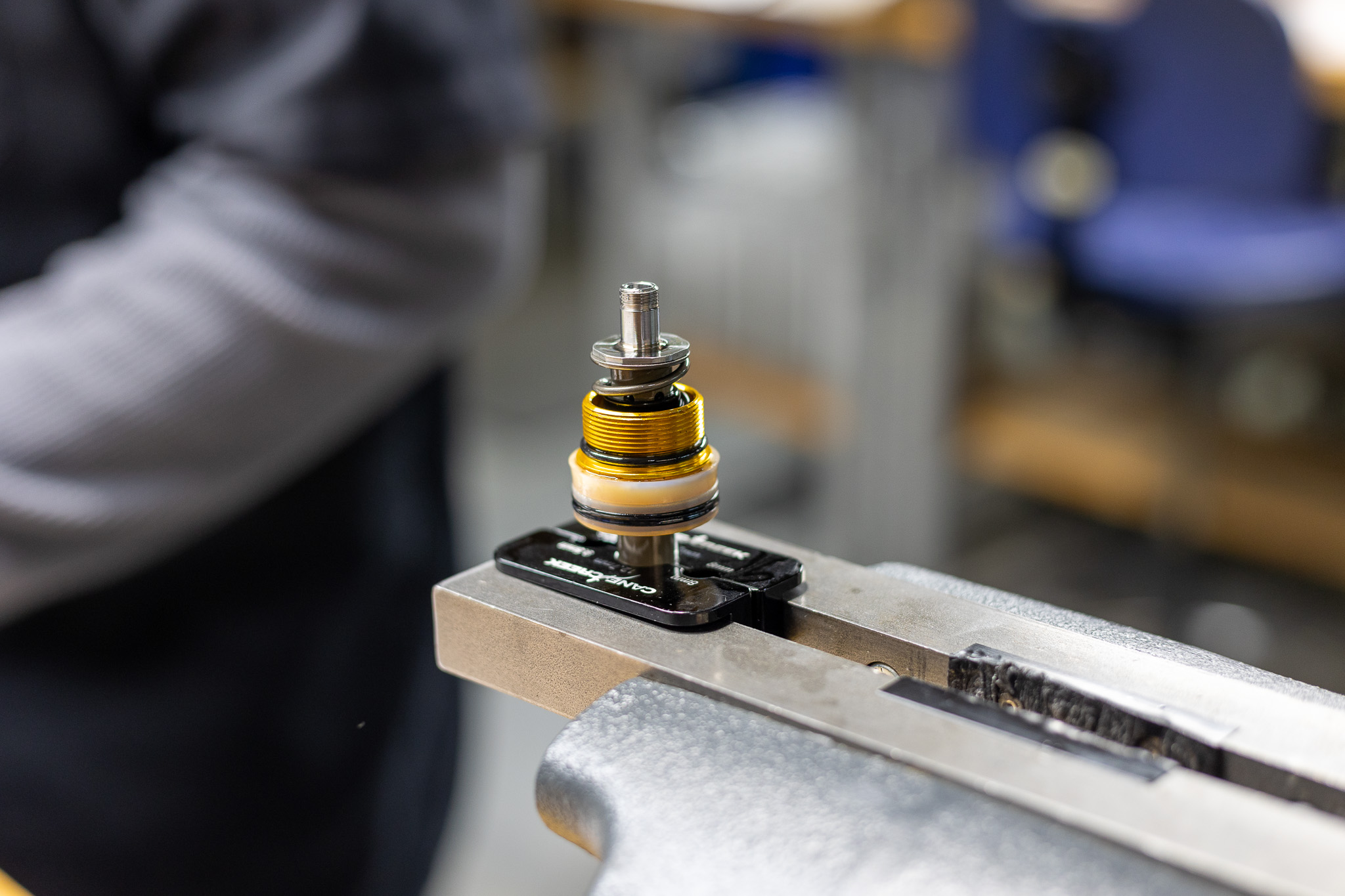
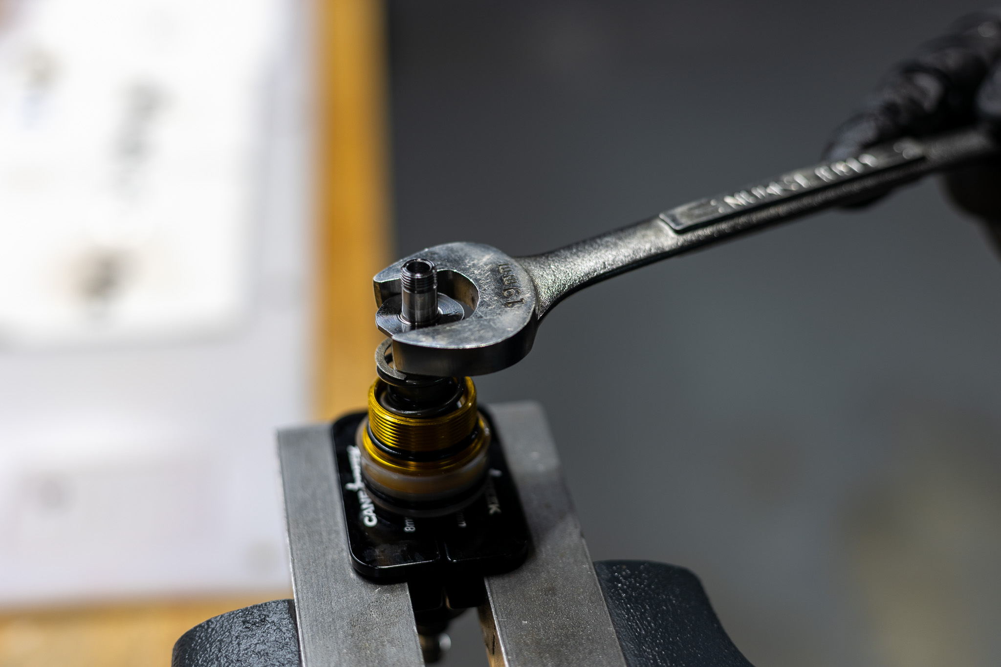
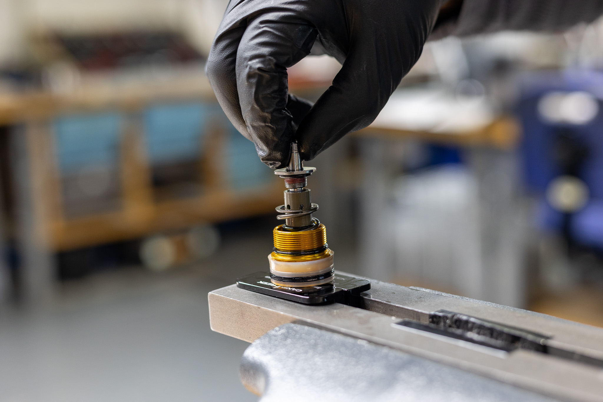
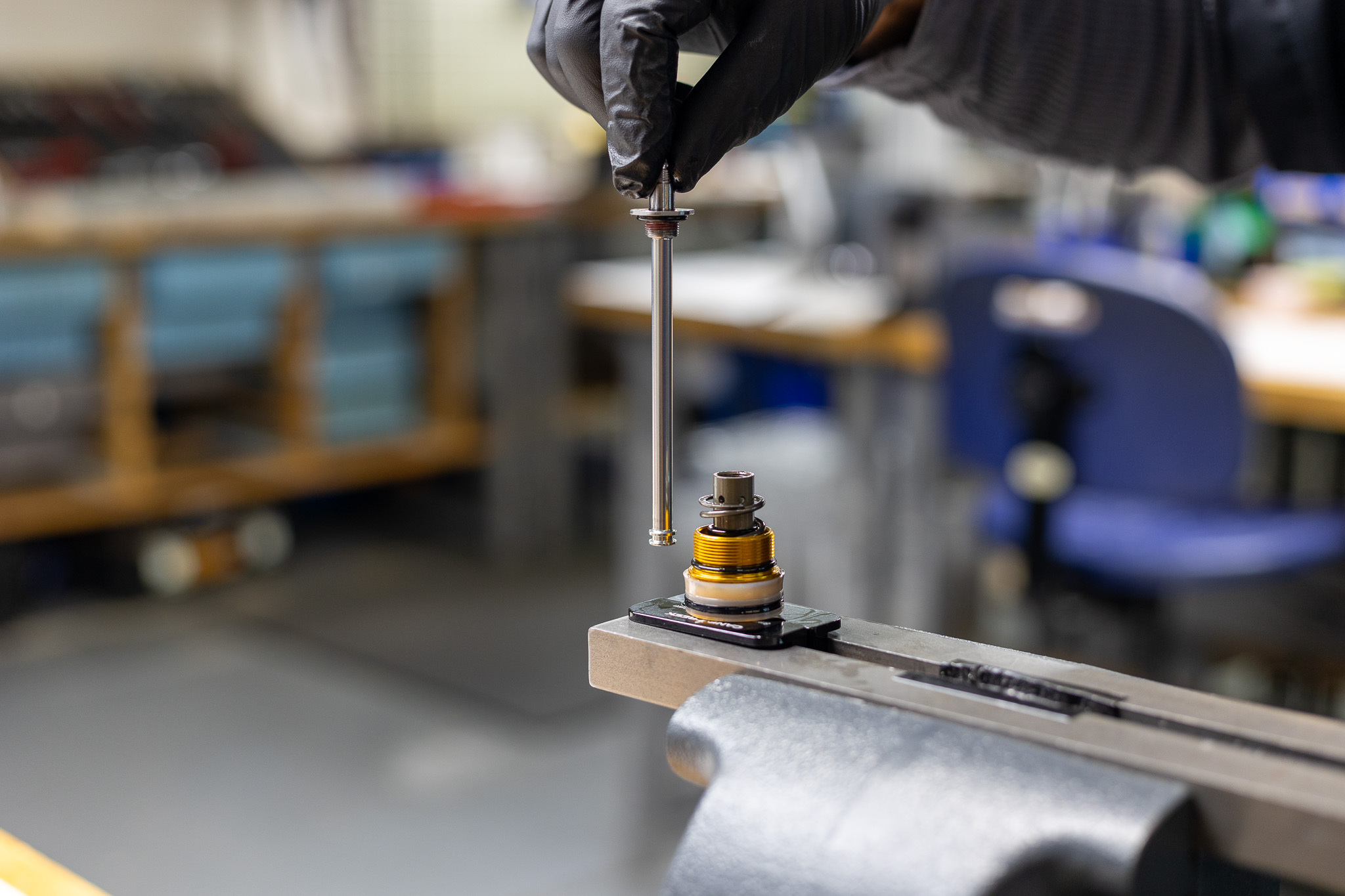
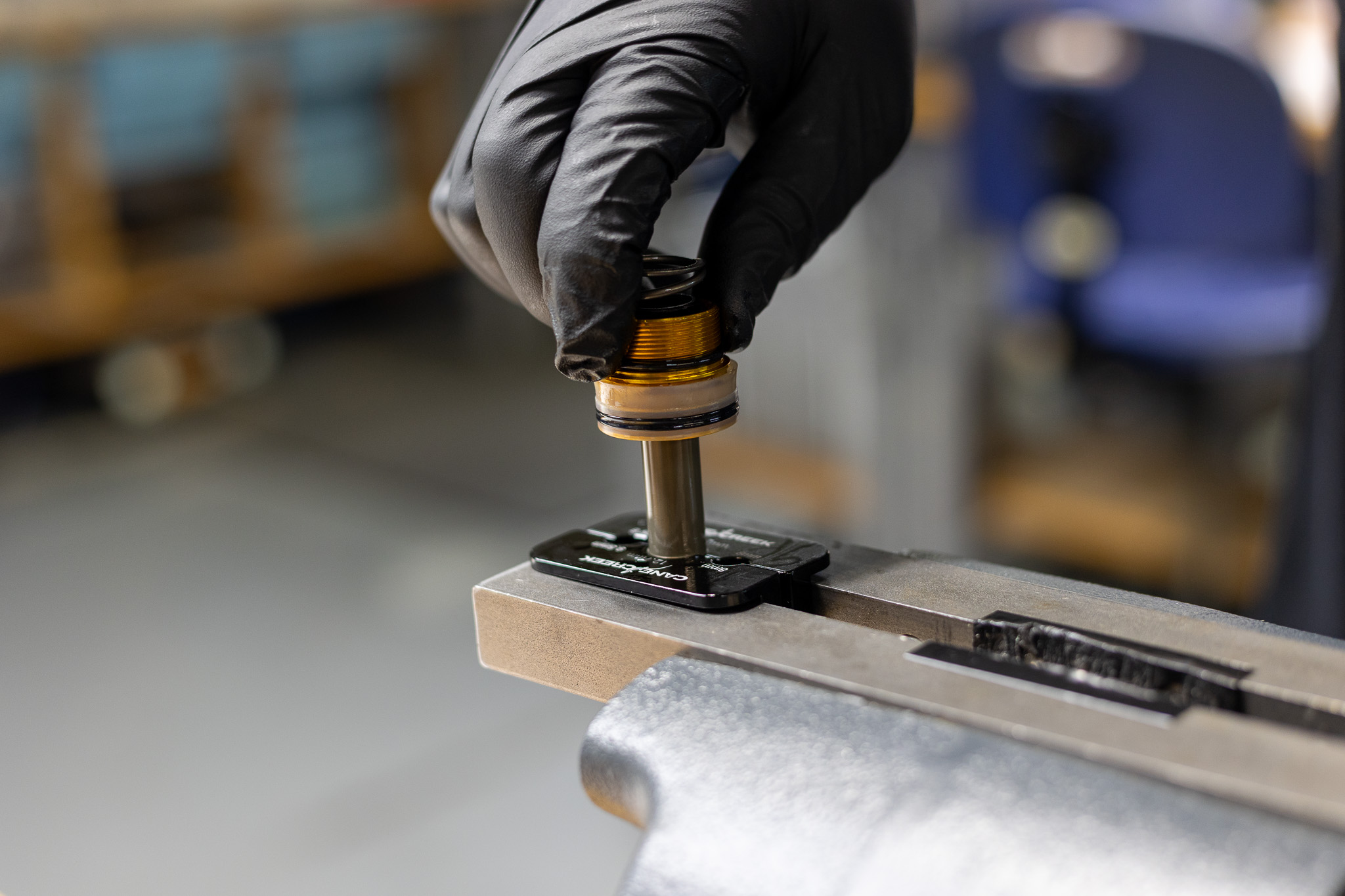
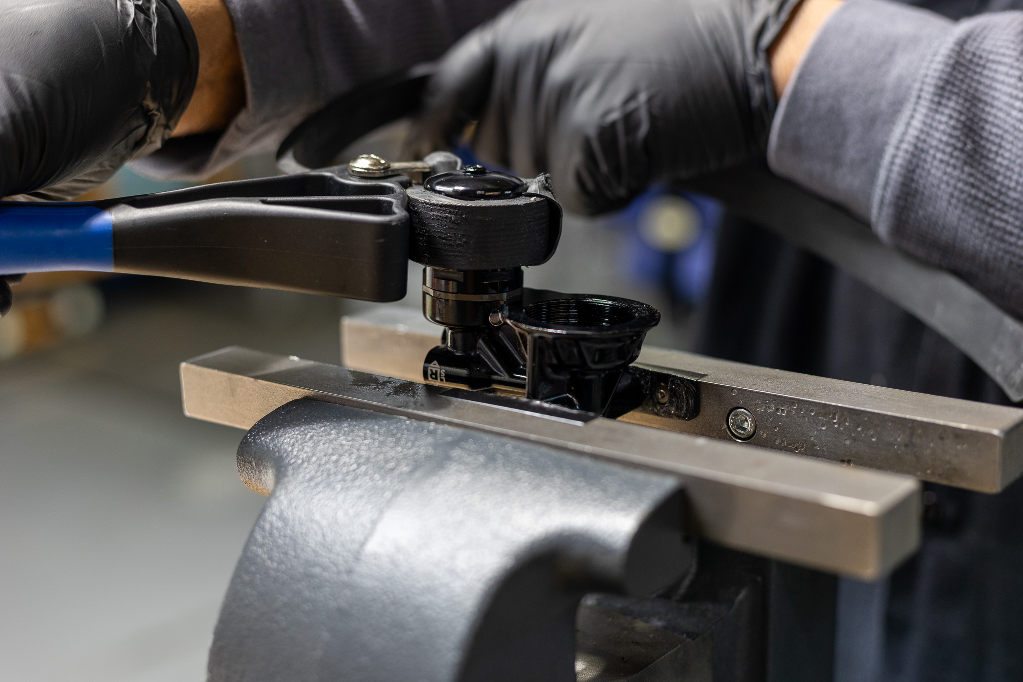
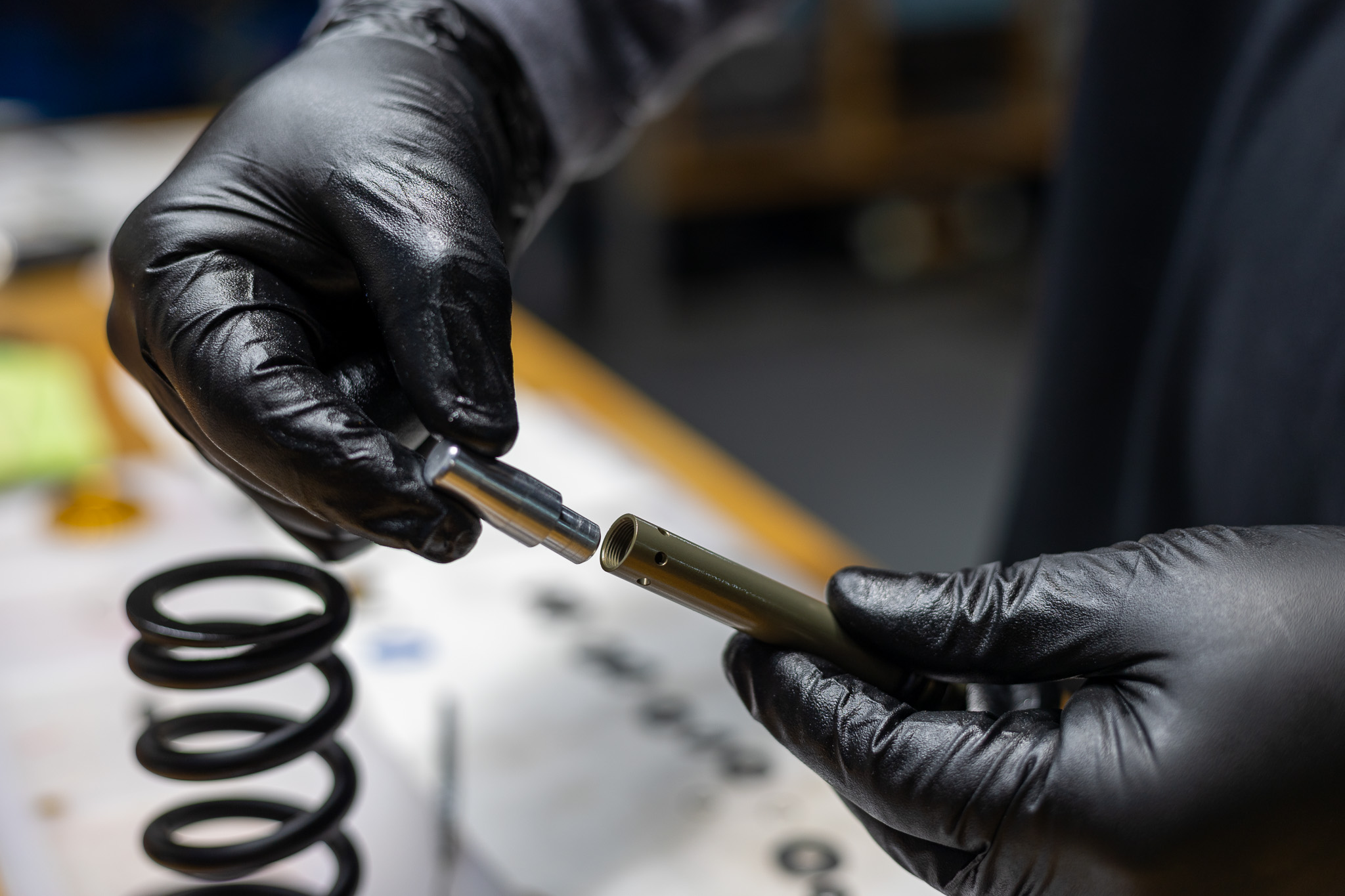
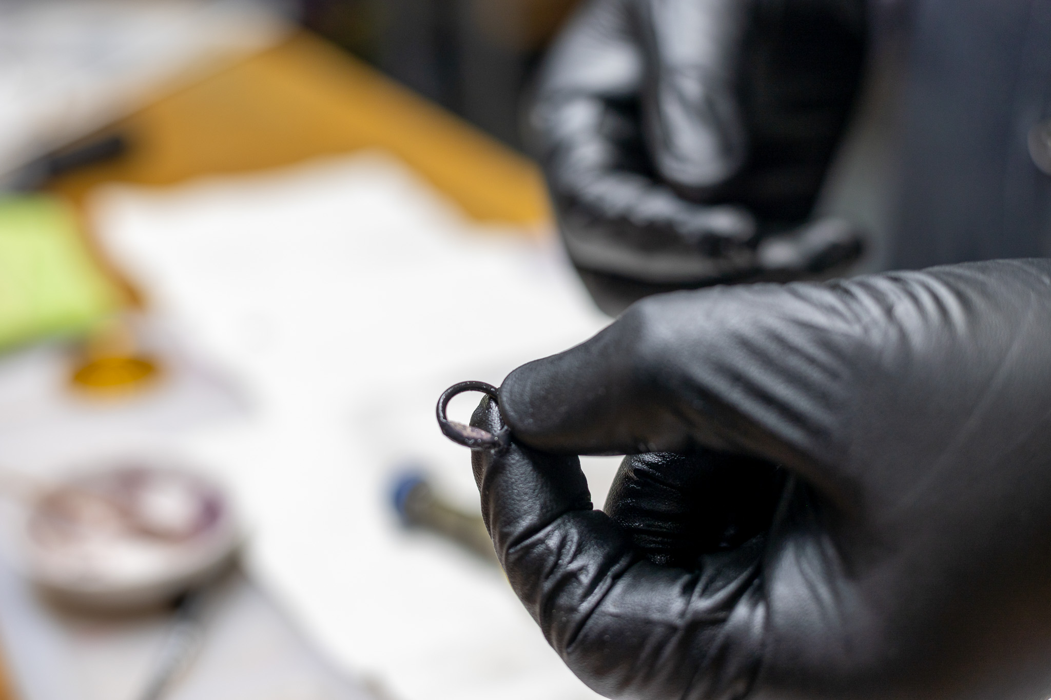
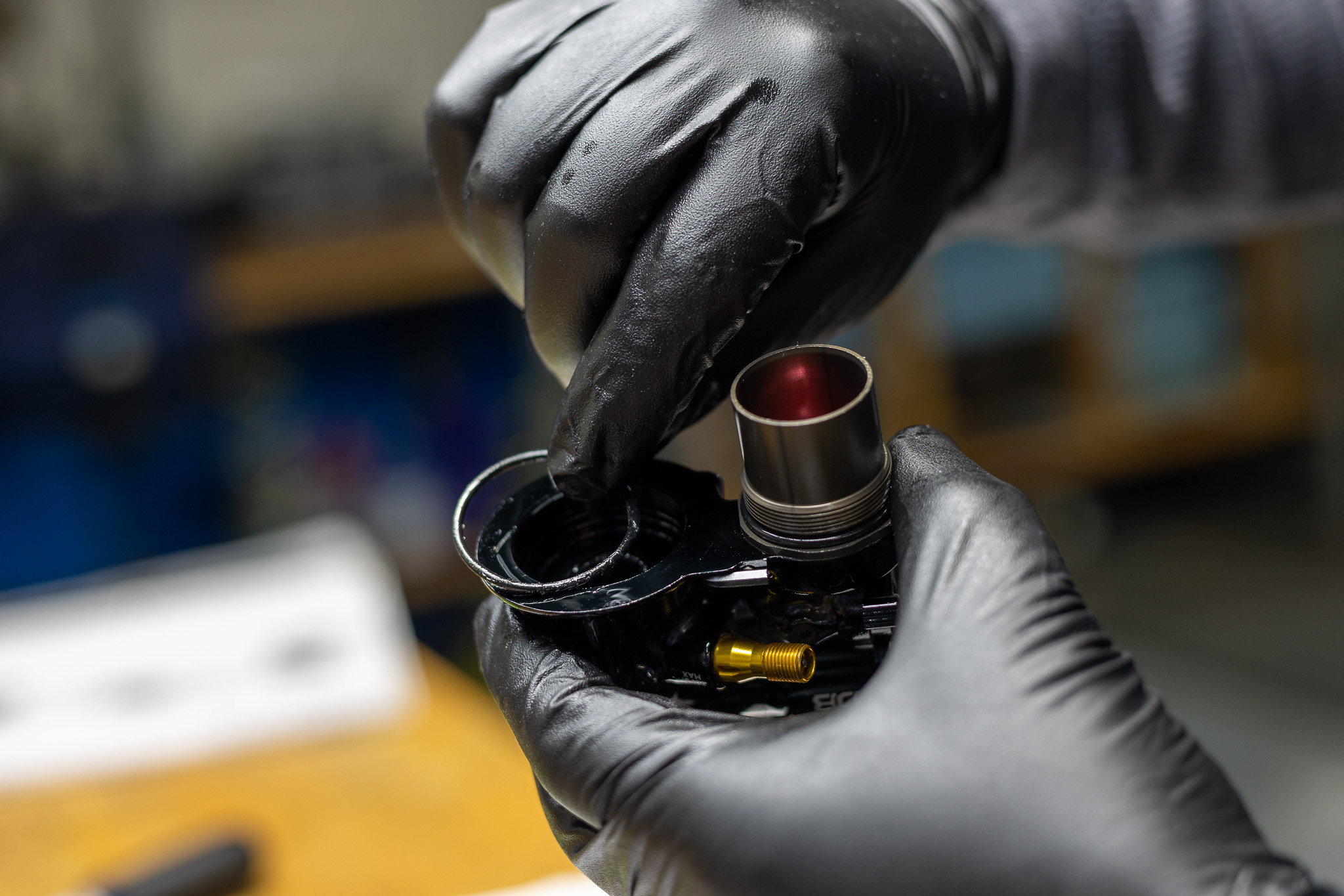
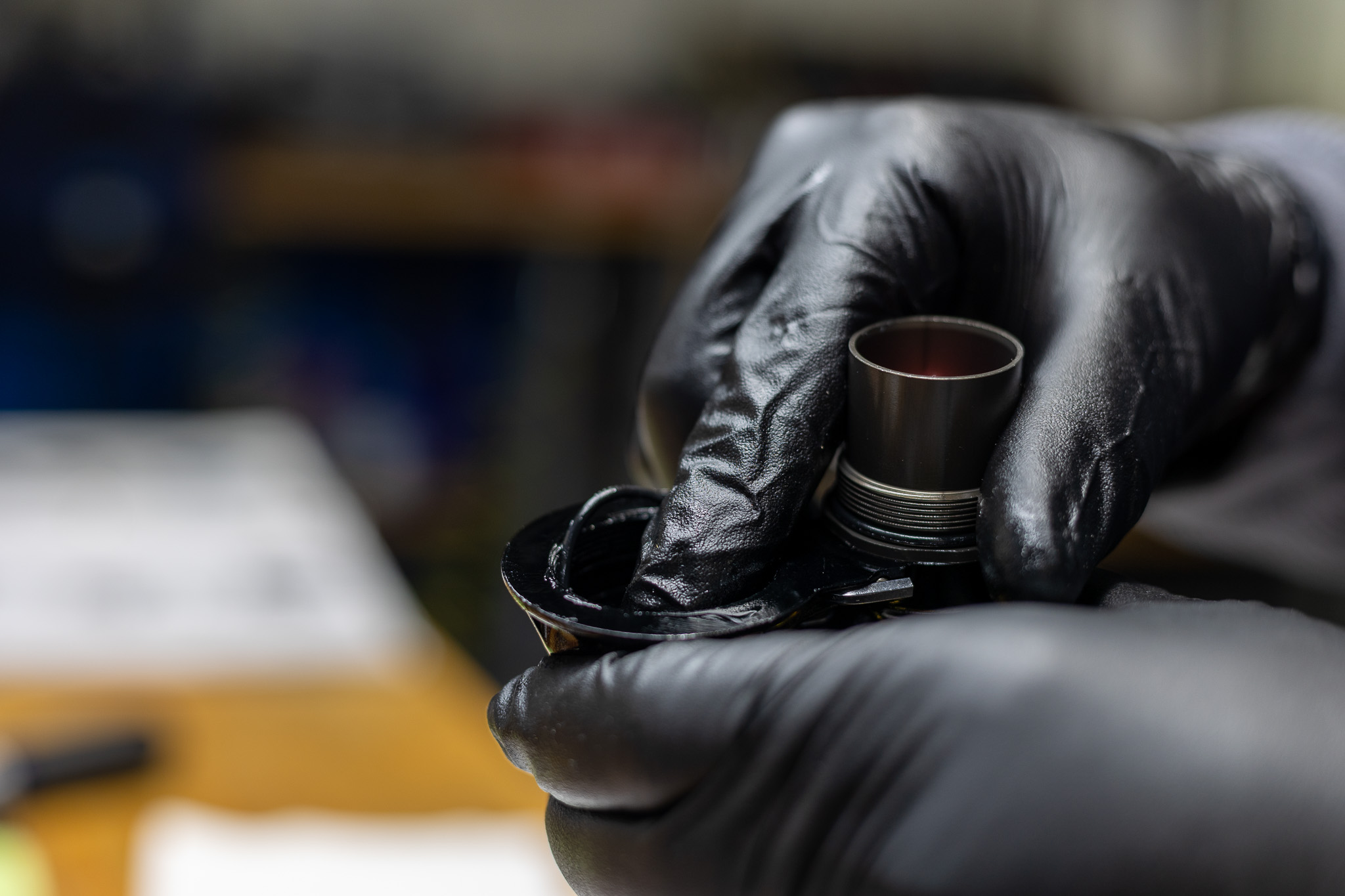
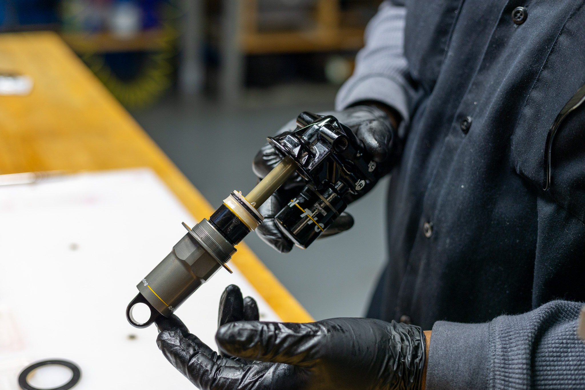
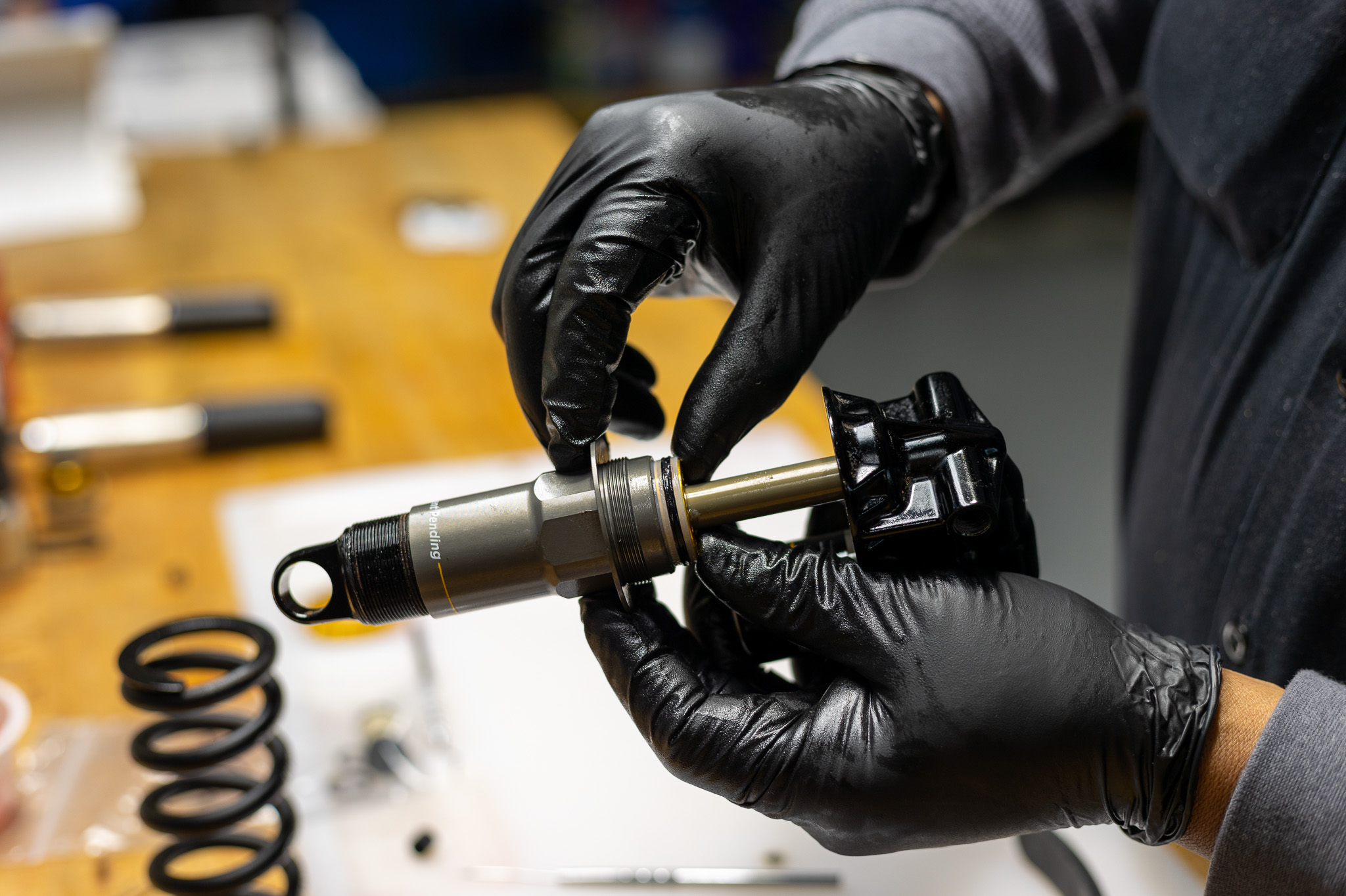
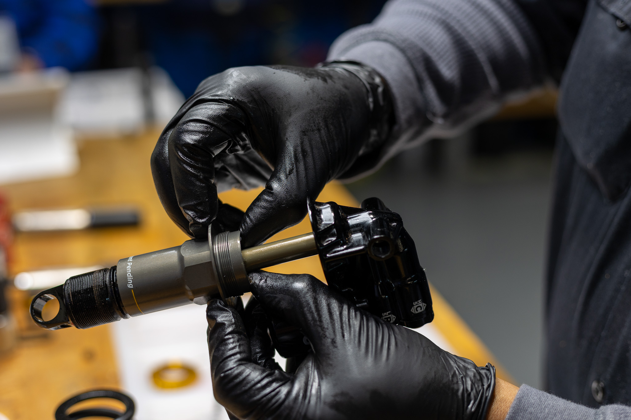
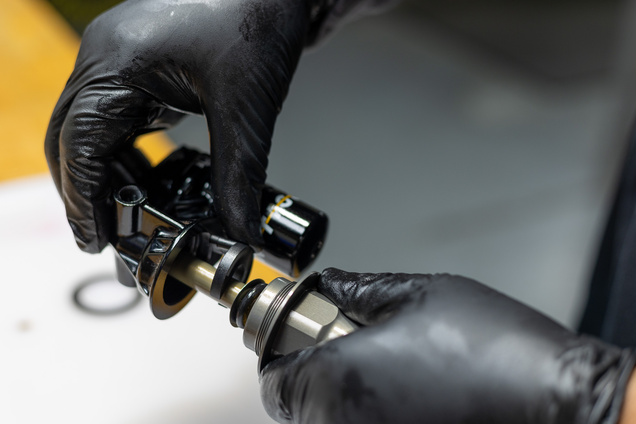
Clamp valve body in soft jaw vise. Using 12mm crowsfoot or socket, loosen shaft assembly via shaft nut. Heat may be used to help free shaft assembly. Remove shaft assembly and any stroke reduction if present. If shaft nut threads off rather than assembly, clamp shaft with 12.7mm shaft clamp and turn valve body to unthread. Using pick, remove both valve body o-rings and discard.
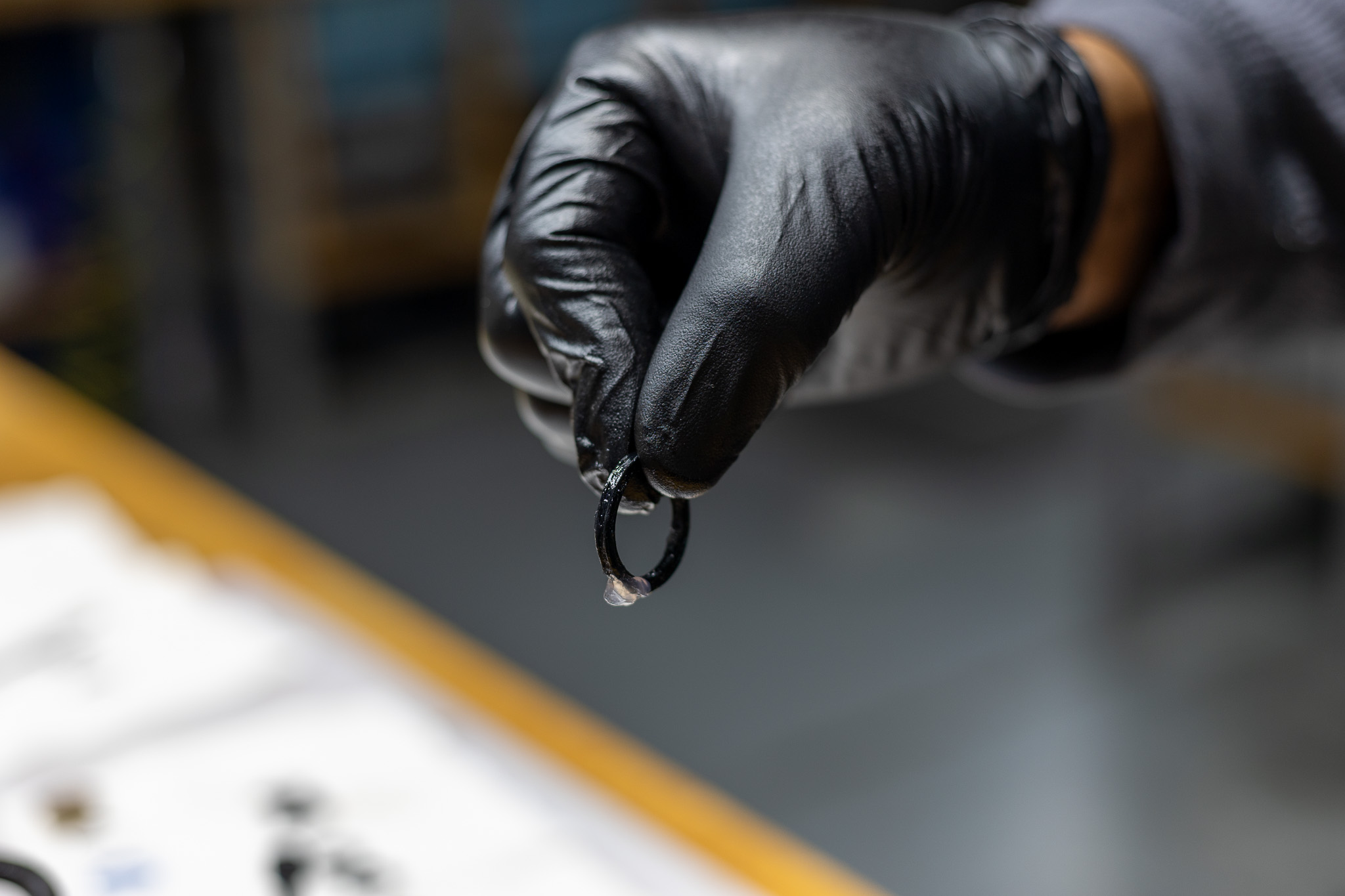
Always use extreme caution when using a pick in this step or others to avoid scratching metal parts. Failure to do this can create scratches in the o-ring glands which cause leak paths for oil or gas. When possible, pinch and remove o-rings rather than using a pick.
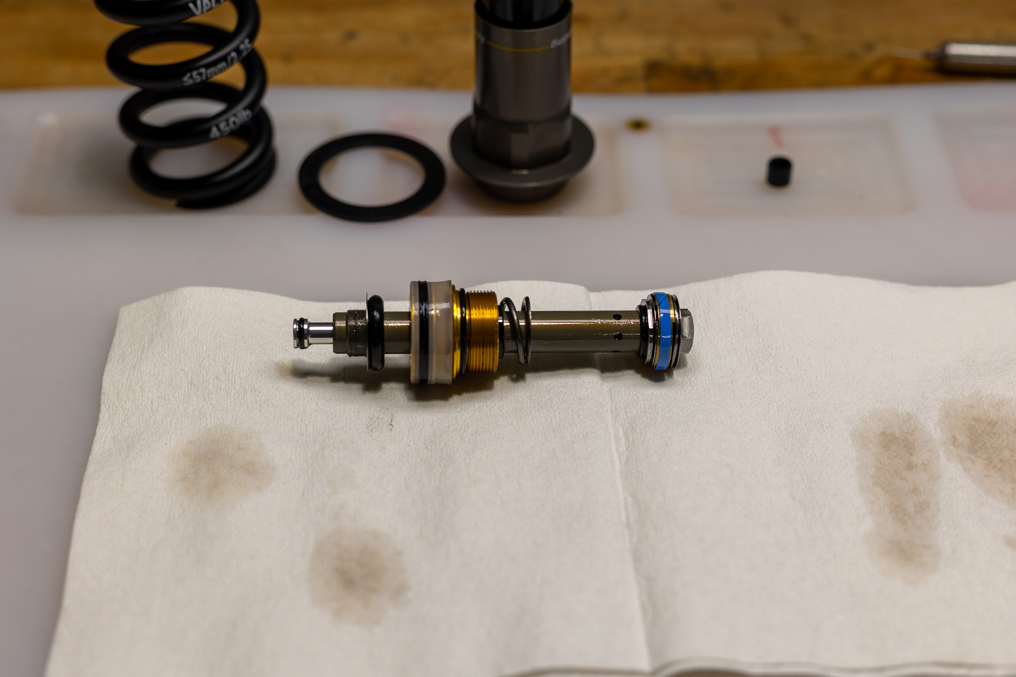
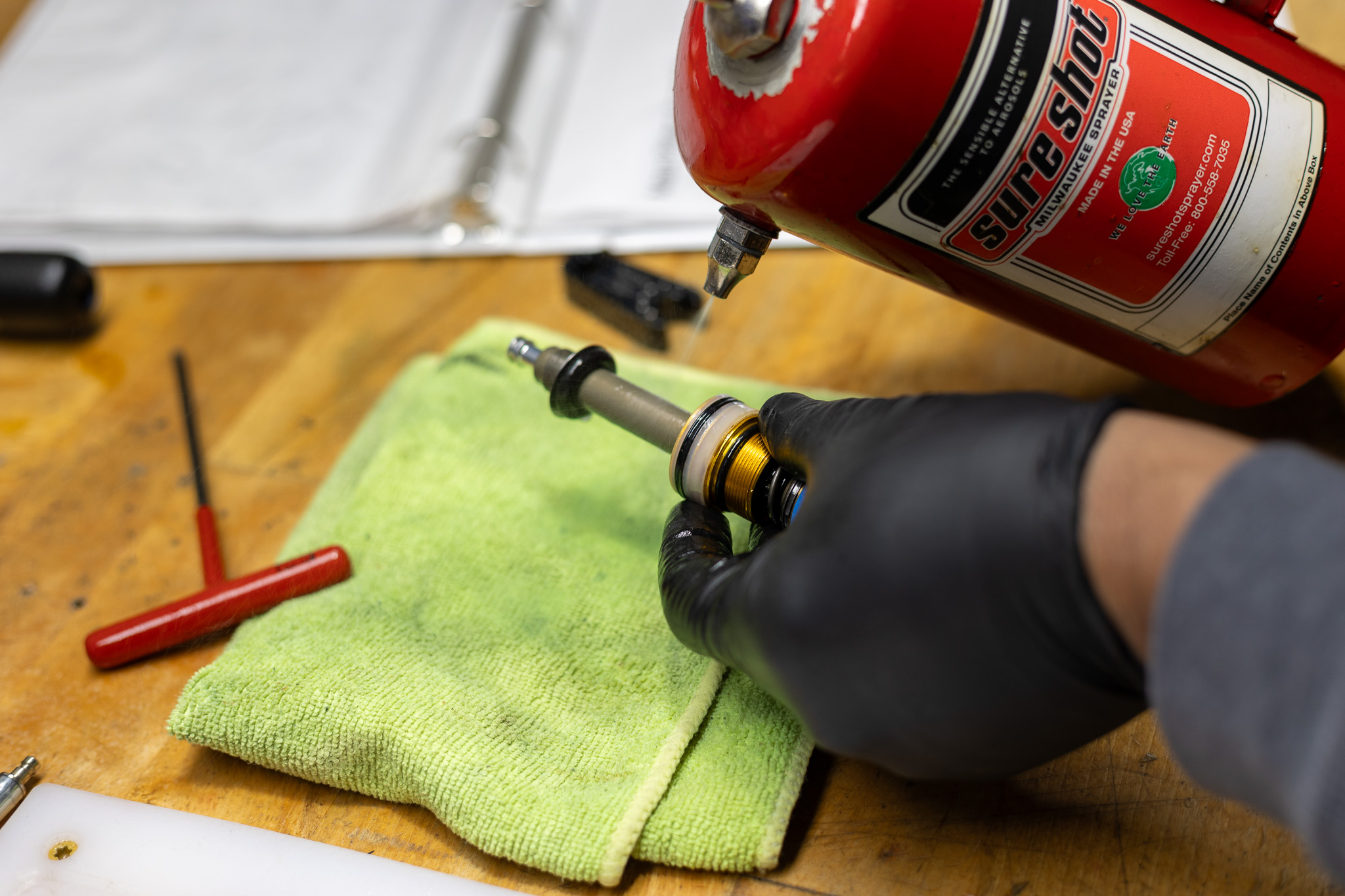
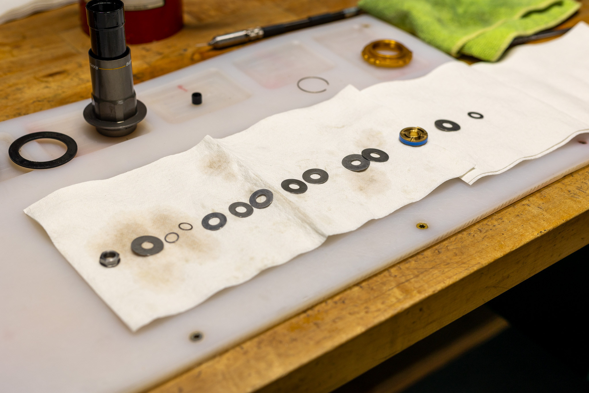
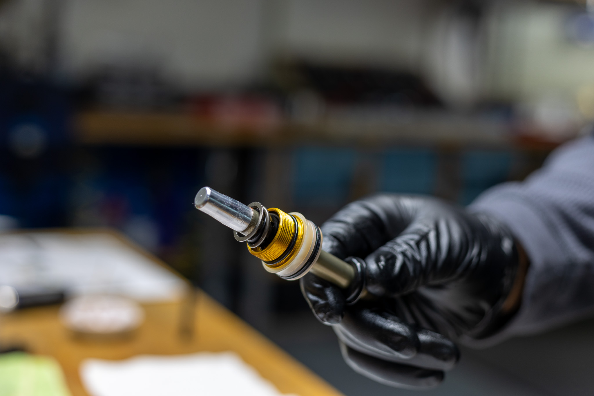
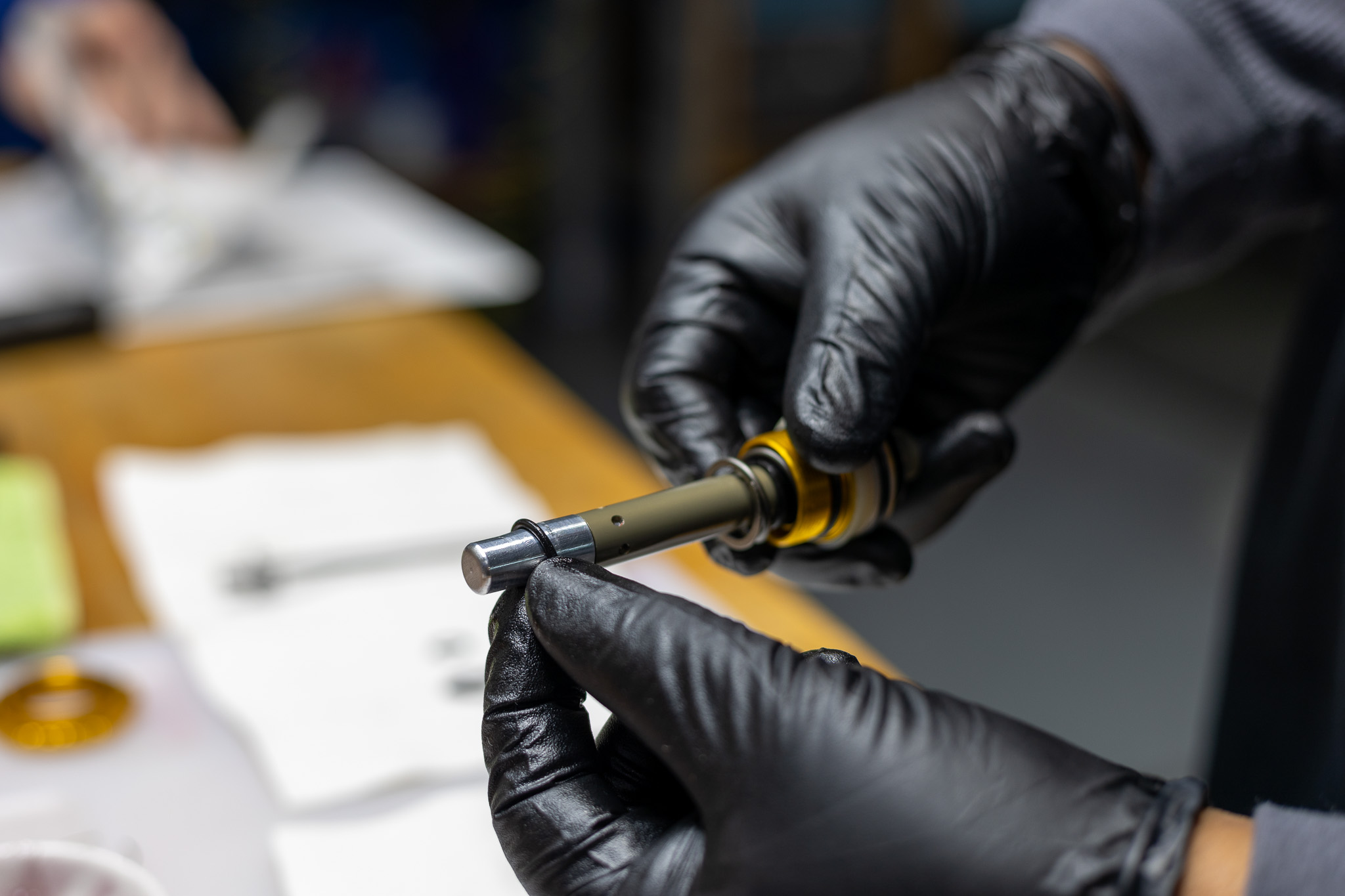
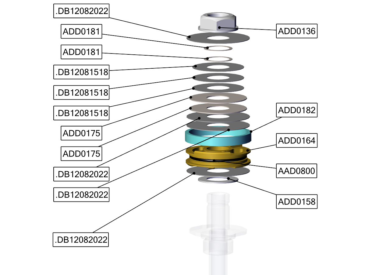
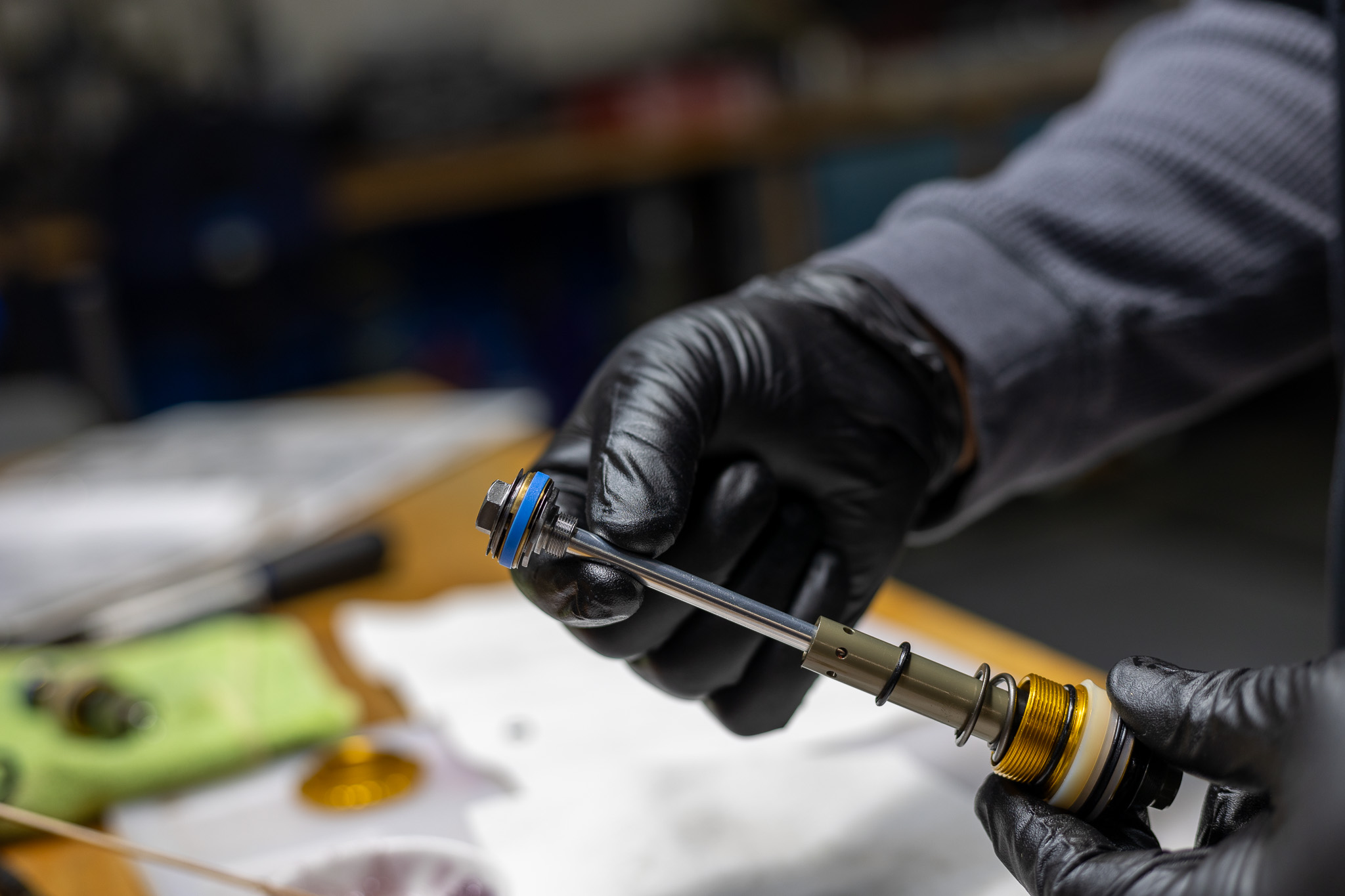
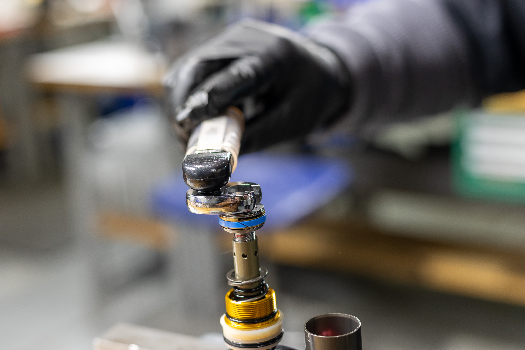
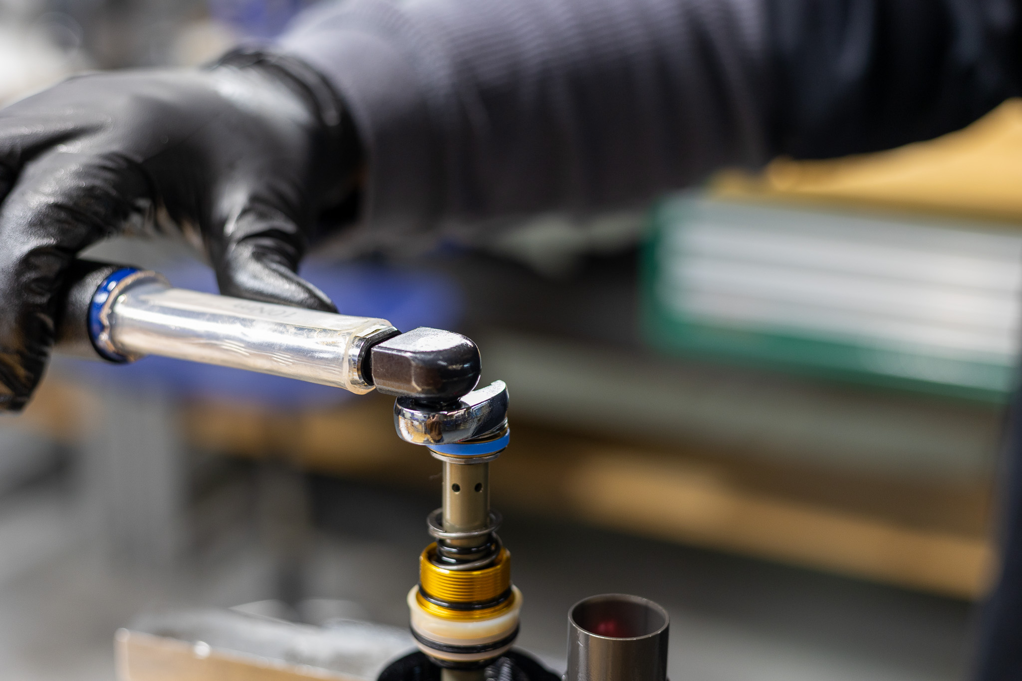
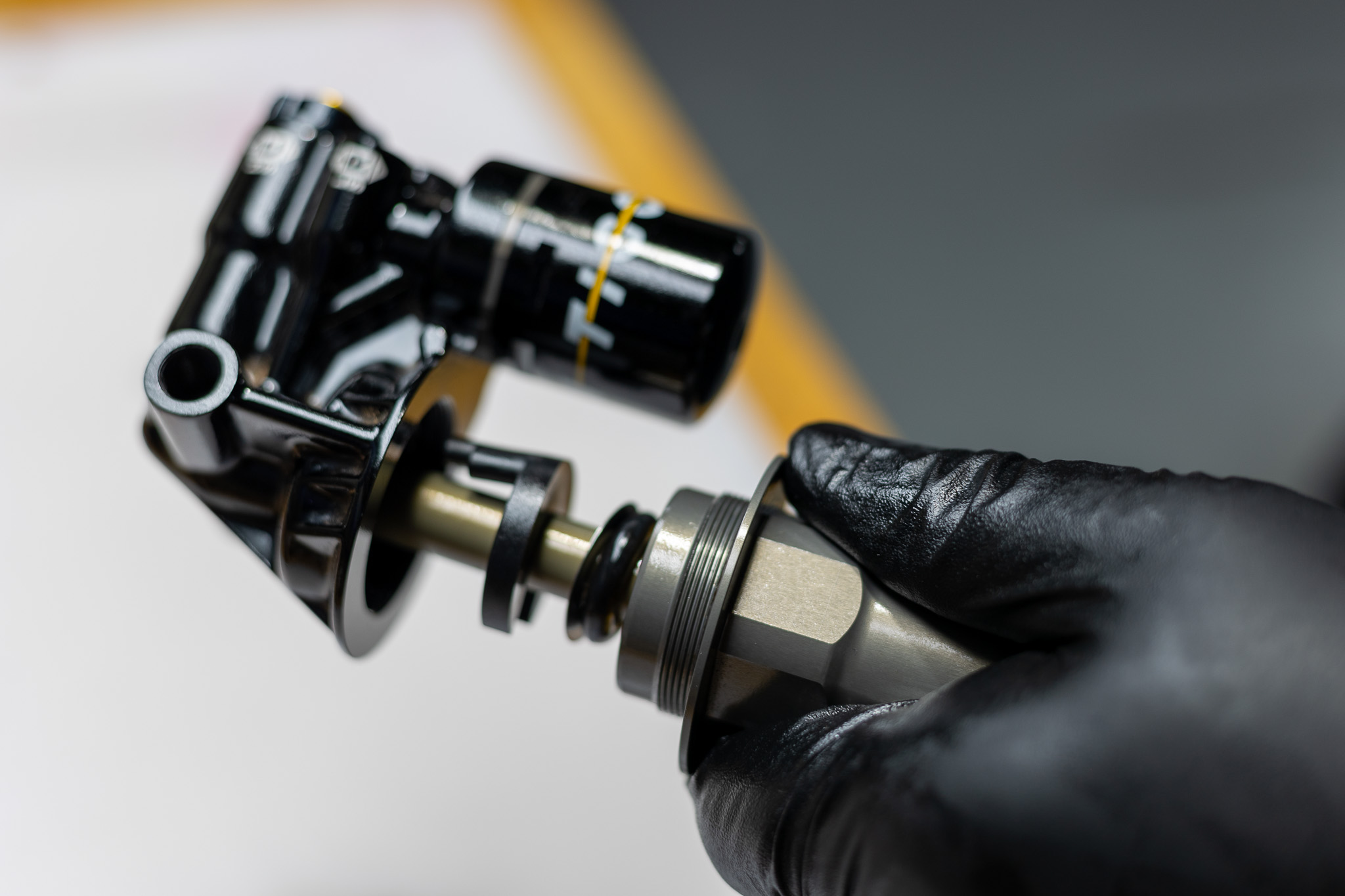
Remove shaft o-ring and discard. Clean shaft threads of any Loctite and thoroughly clean shaft assembly. Using 12.7mm shaft clamp, secure shaft assembly in vise with piston up. With 12mm crowsfoot or socket, loosen shaft nut and remove. Remove piston and shim stack, noting shim sequence. Remove and discard piston band and o-ring.
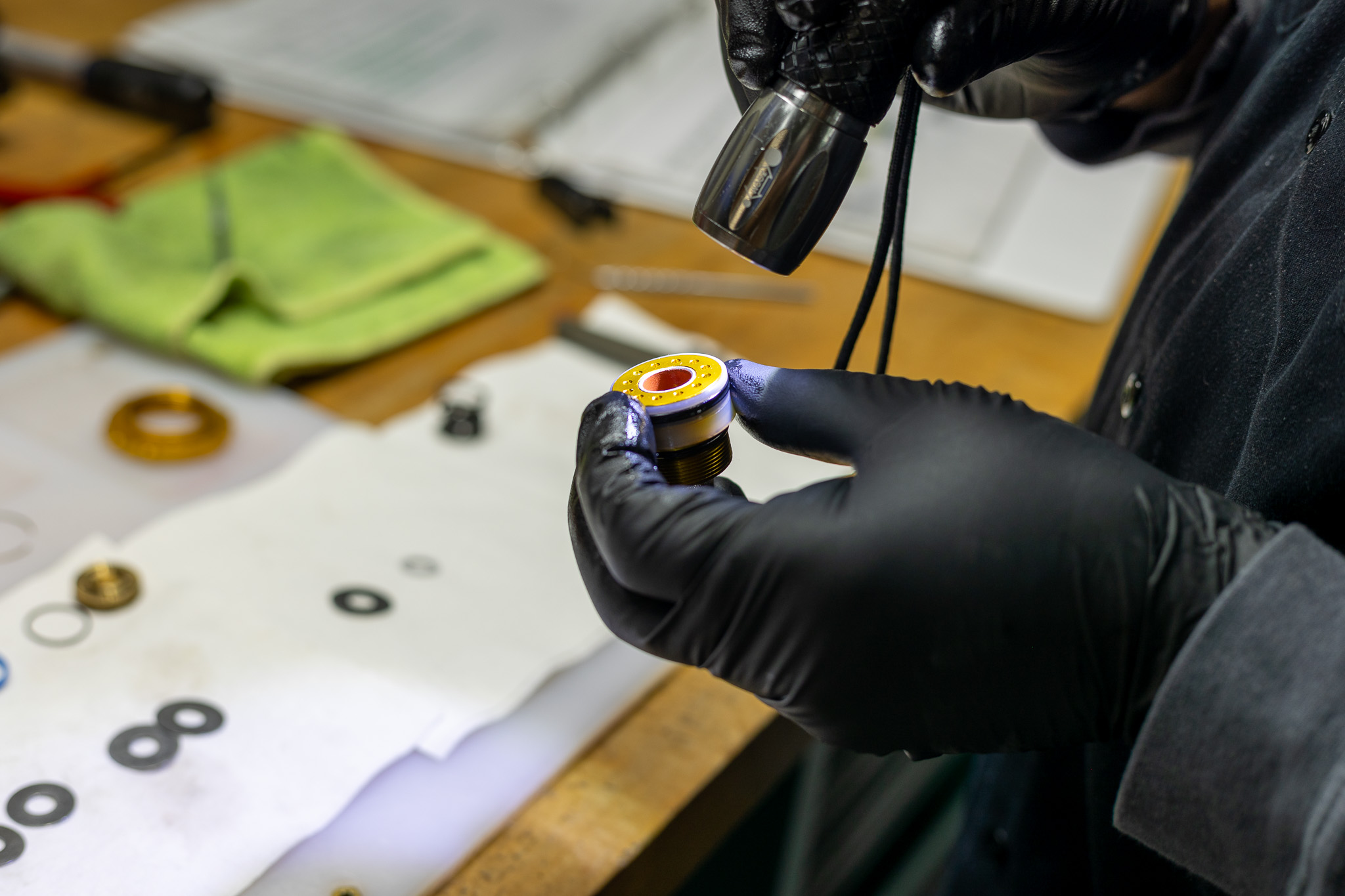
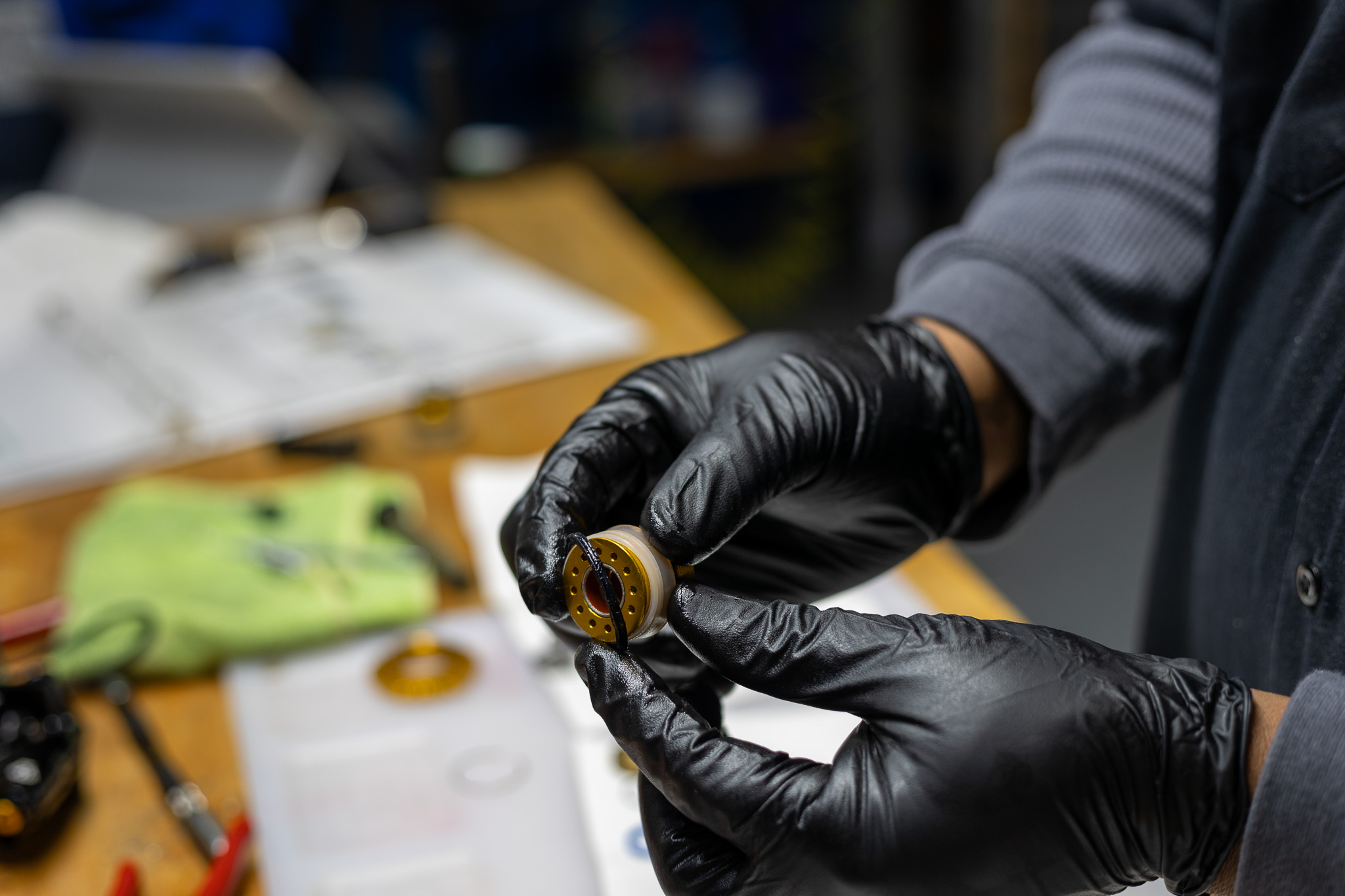
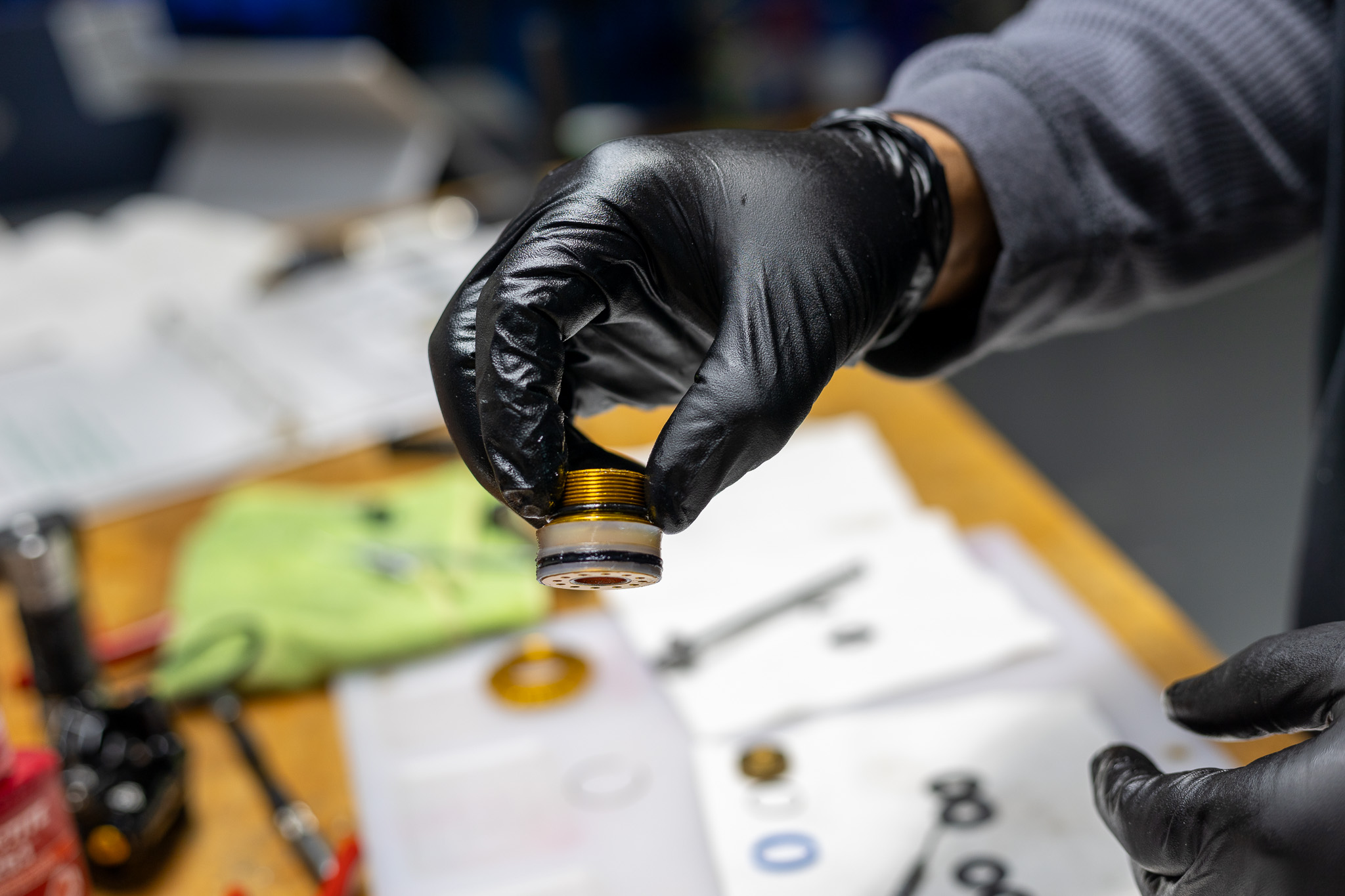
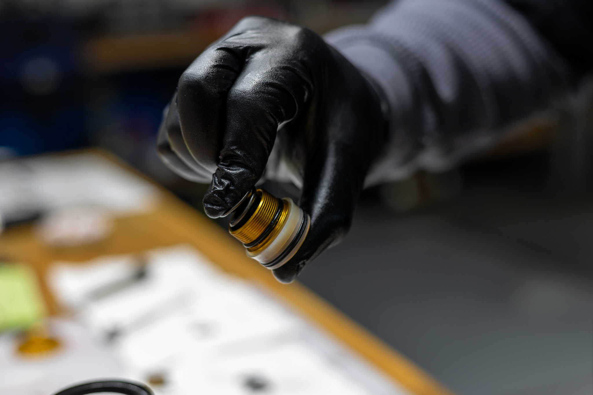
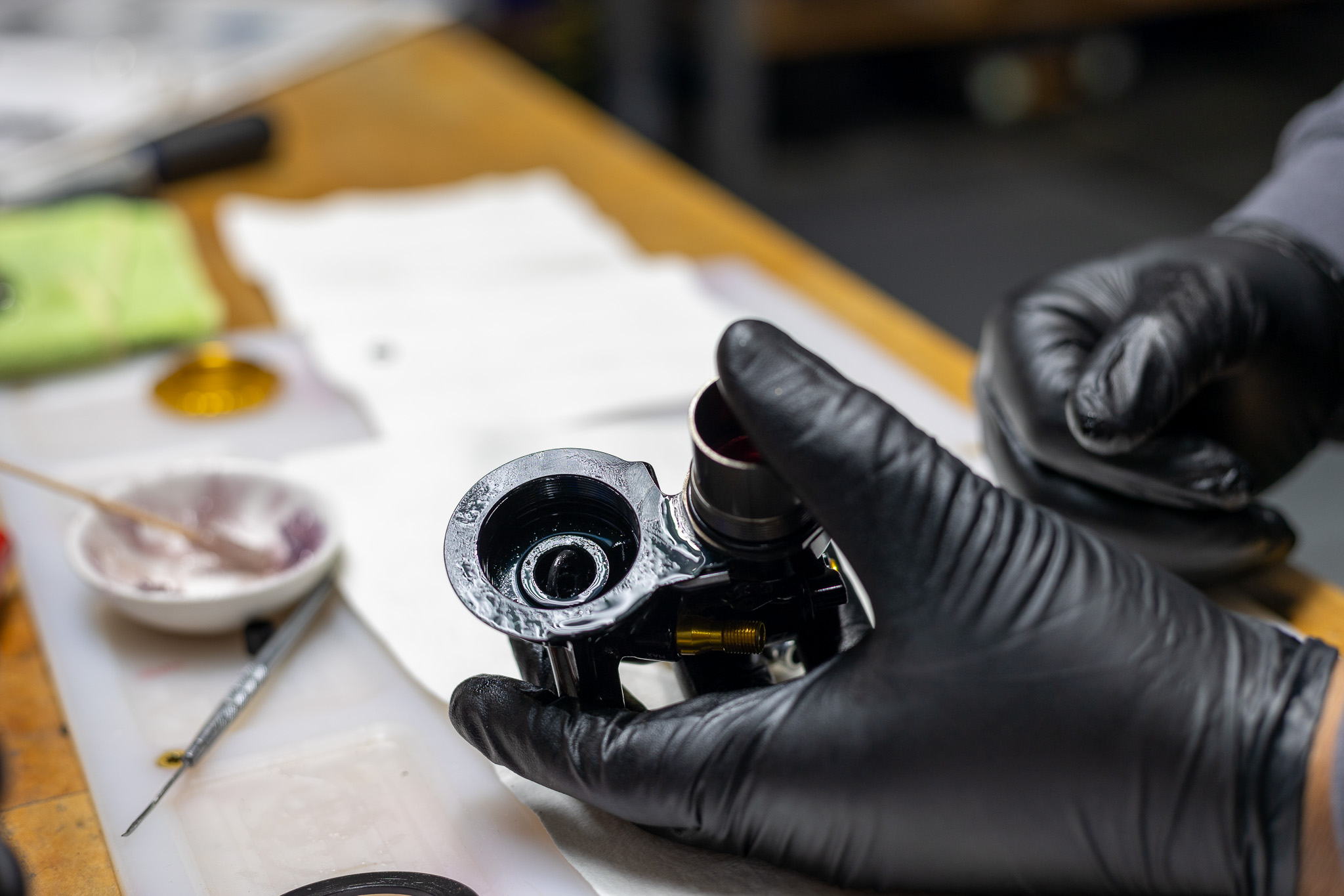
Inspect Oil Seal Head for bearing wear. If worn, discard and replace entire assembly (200 hour service). If bearings are in good condition, proceed with disassembly.
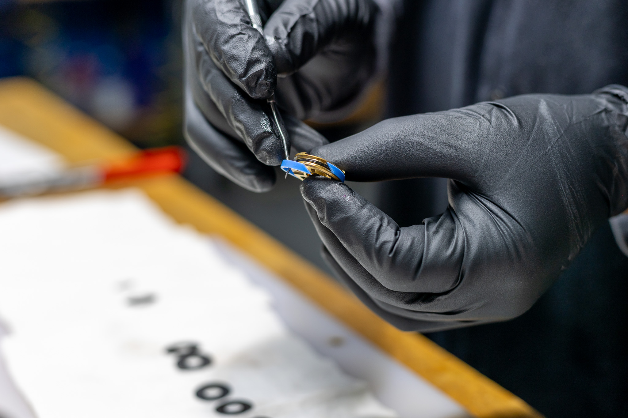
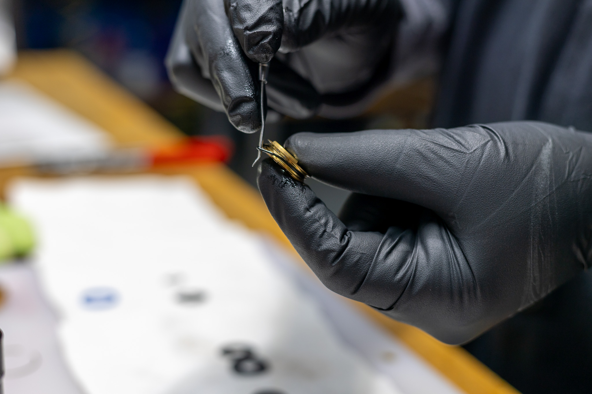
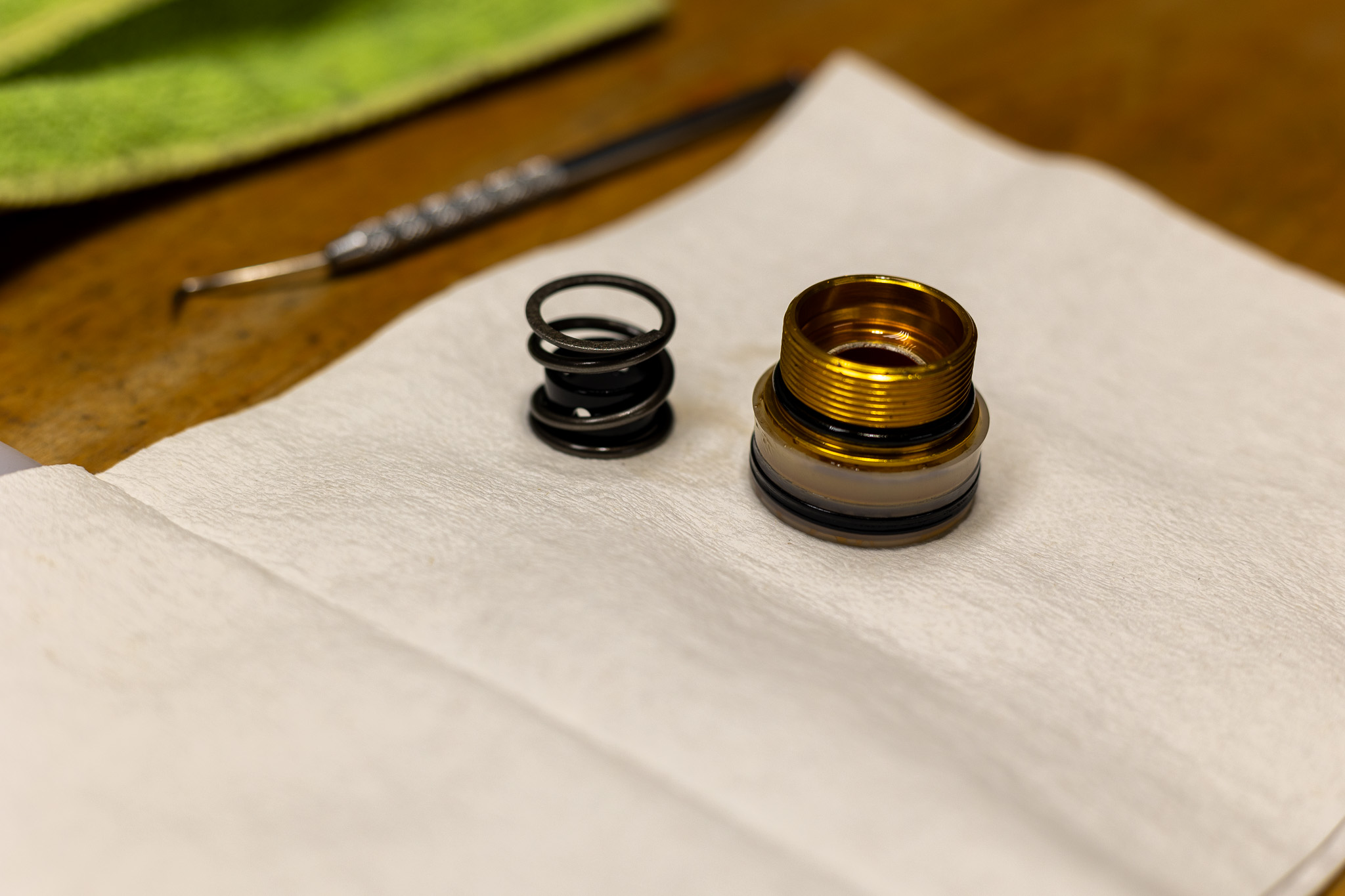
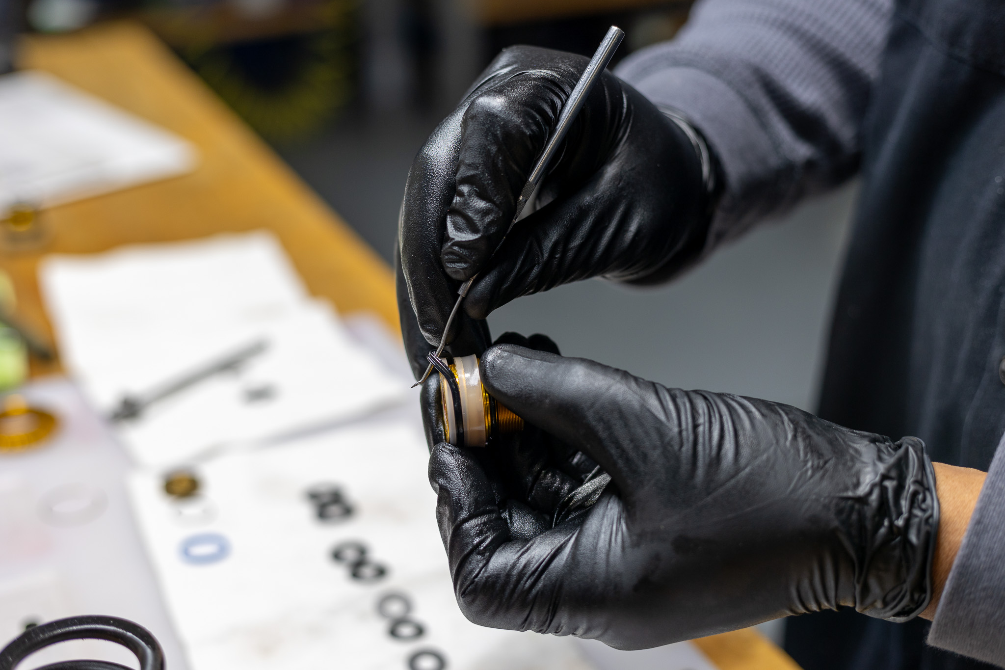
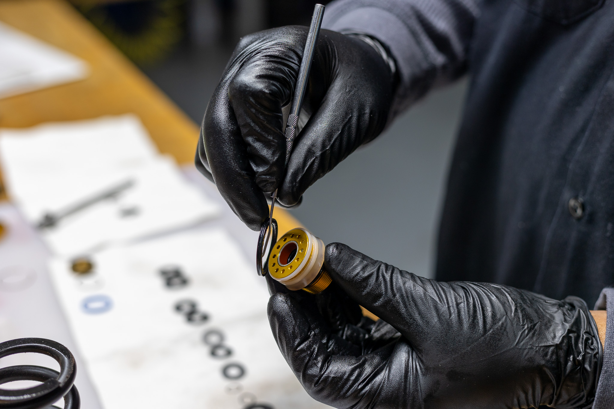
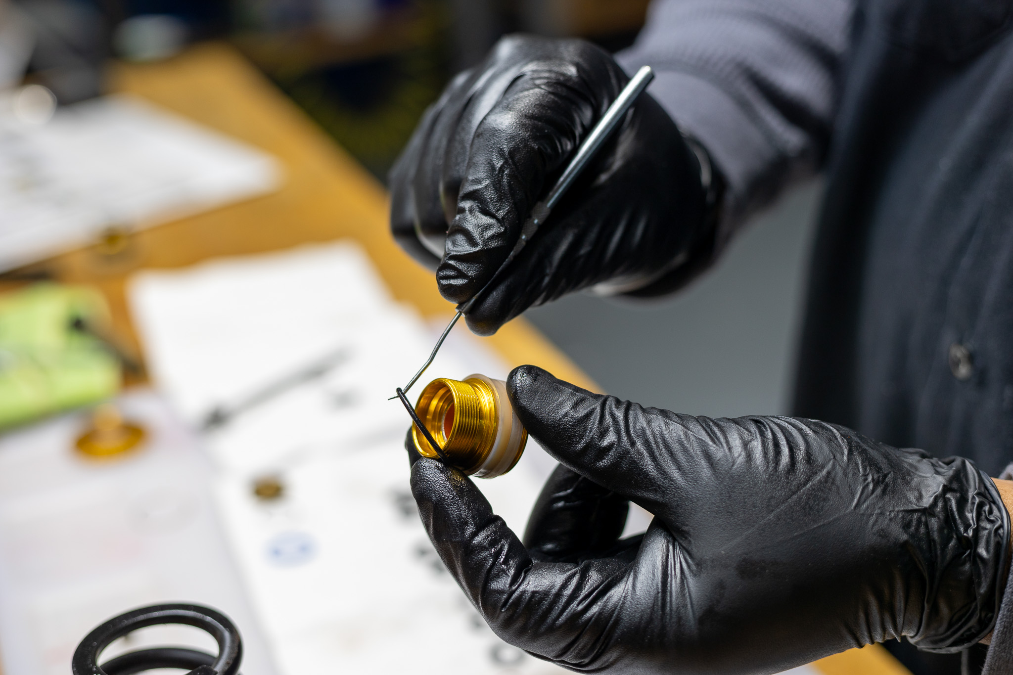
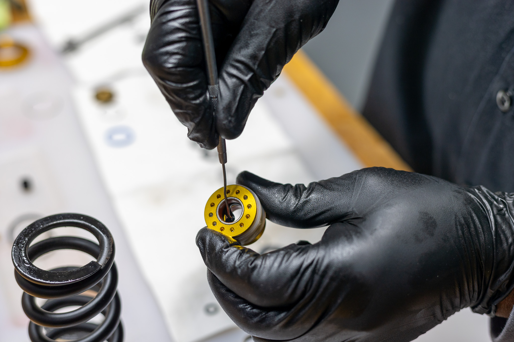
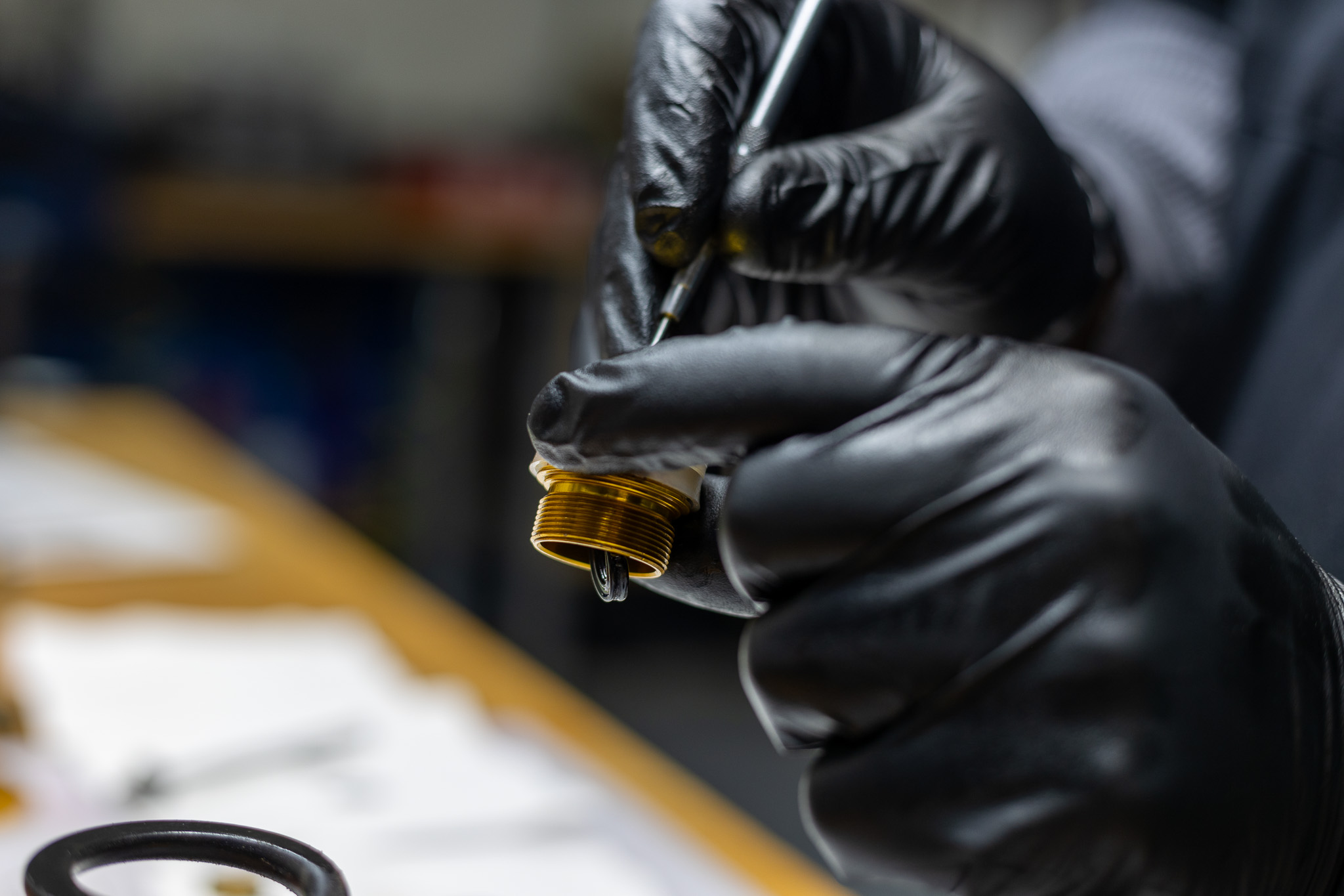
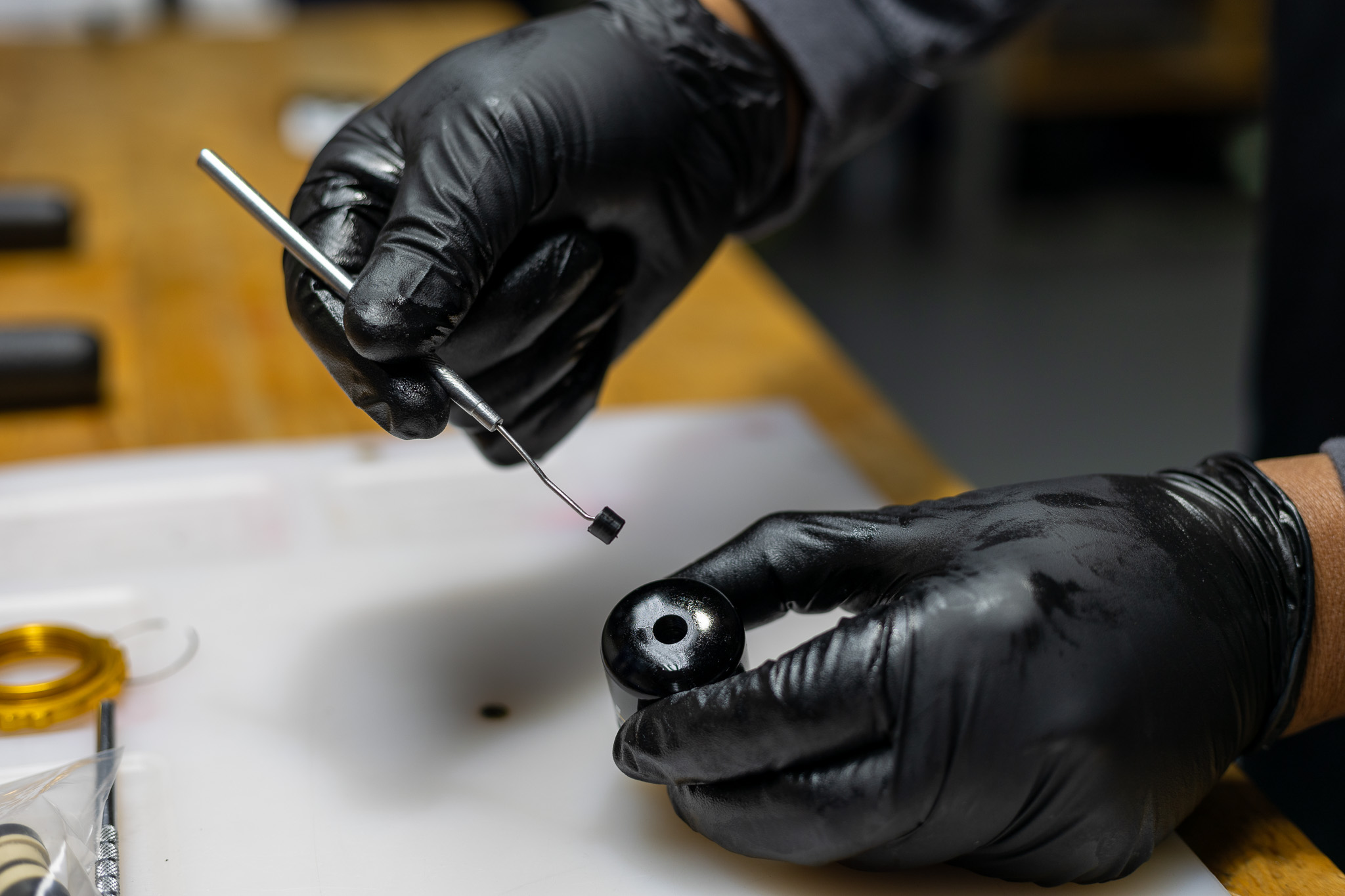
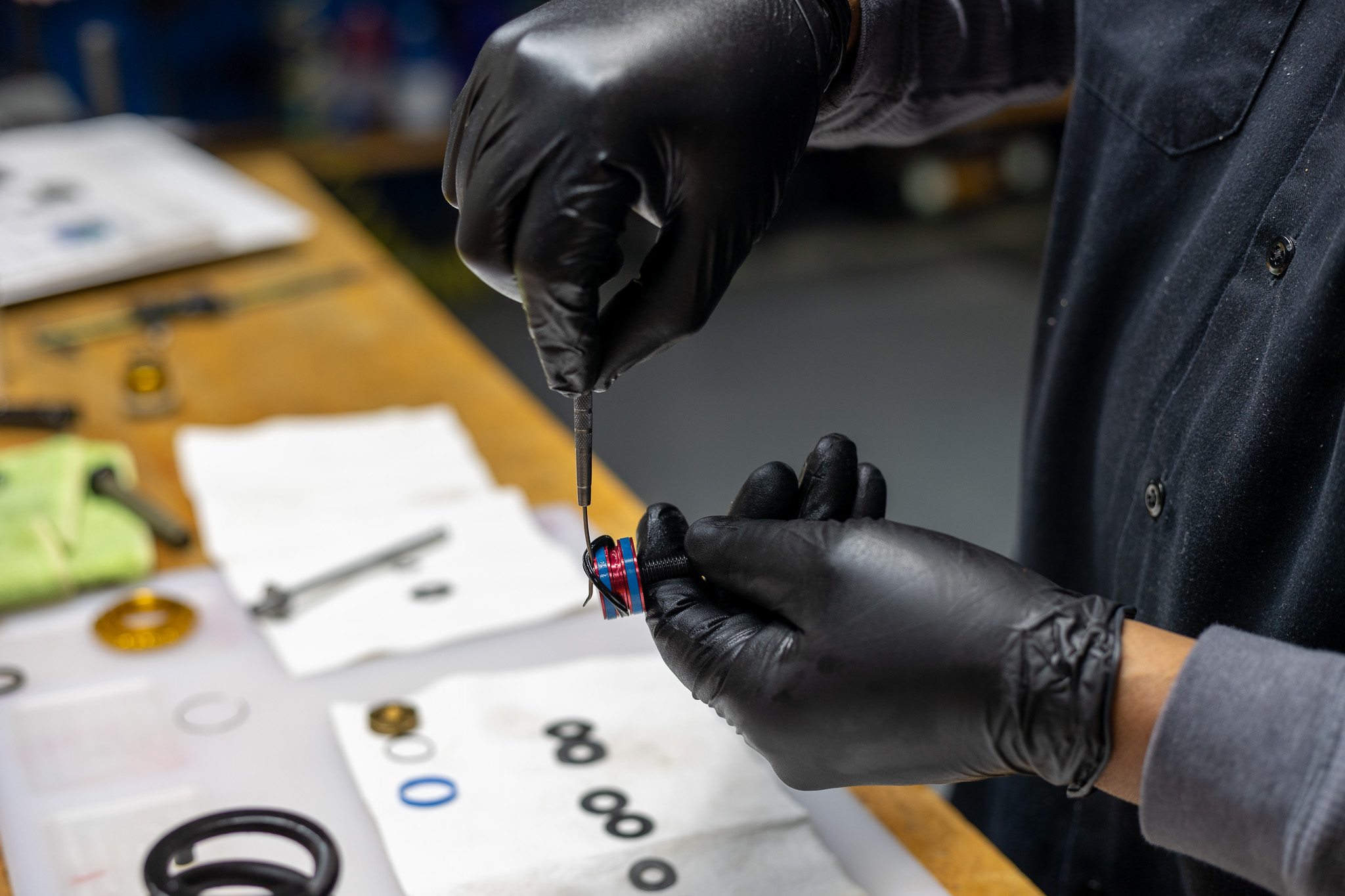
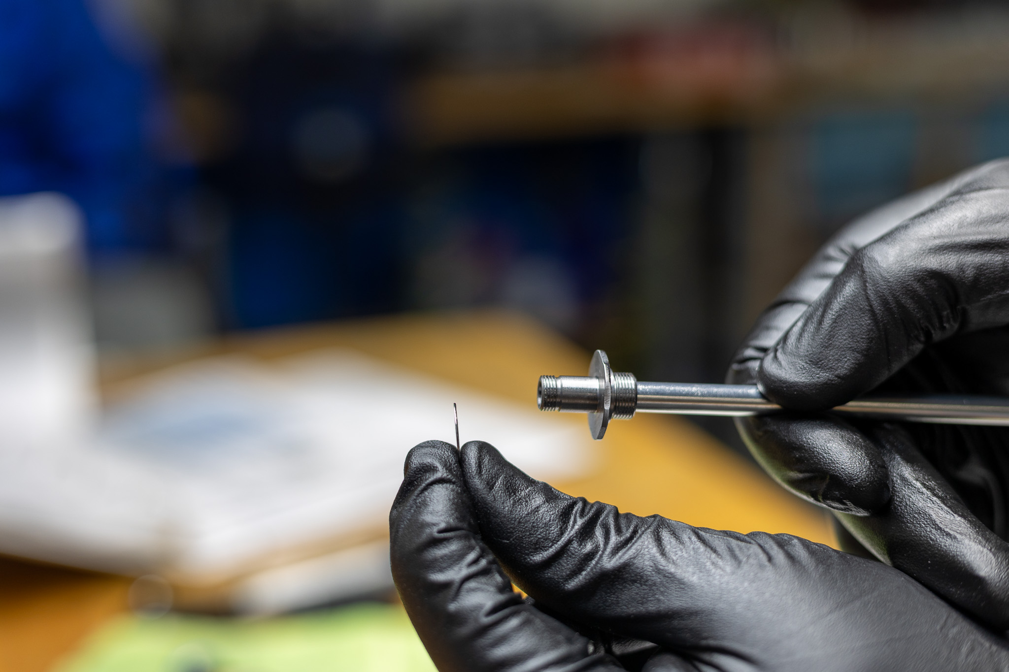
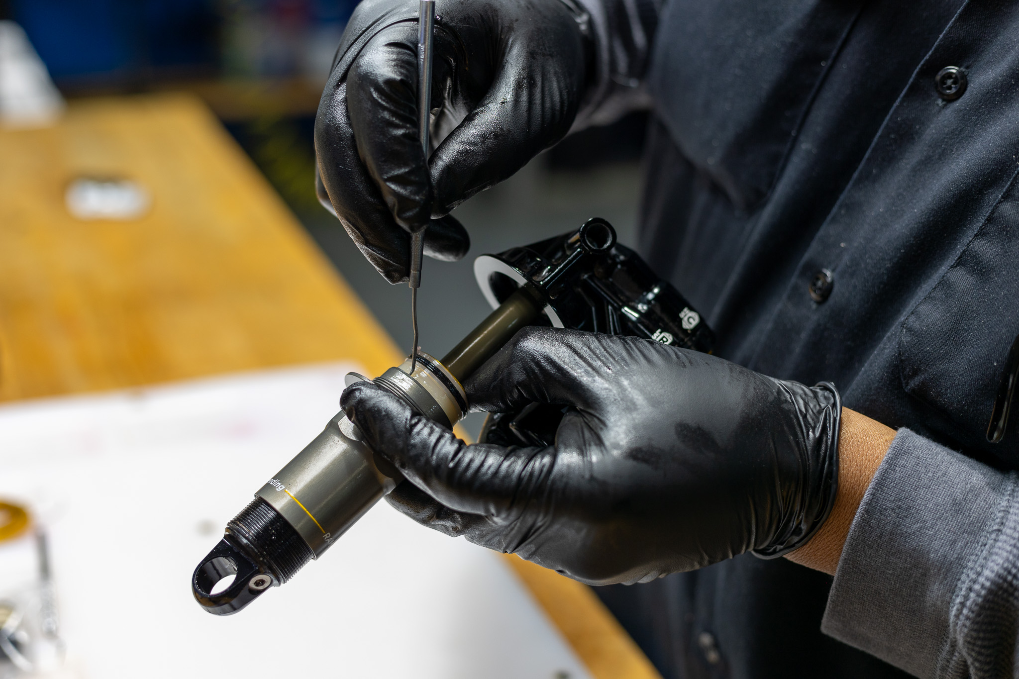
Using pick, remove internal quad ring, external quad ring & o-ring and discard. Thoroughly clean seal head assembly (100 hour service).
Inspect shaft for wear.
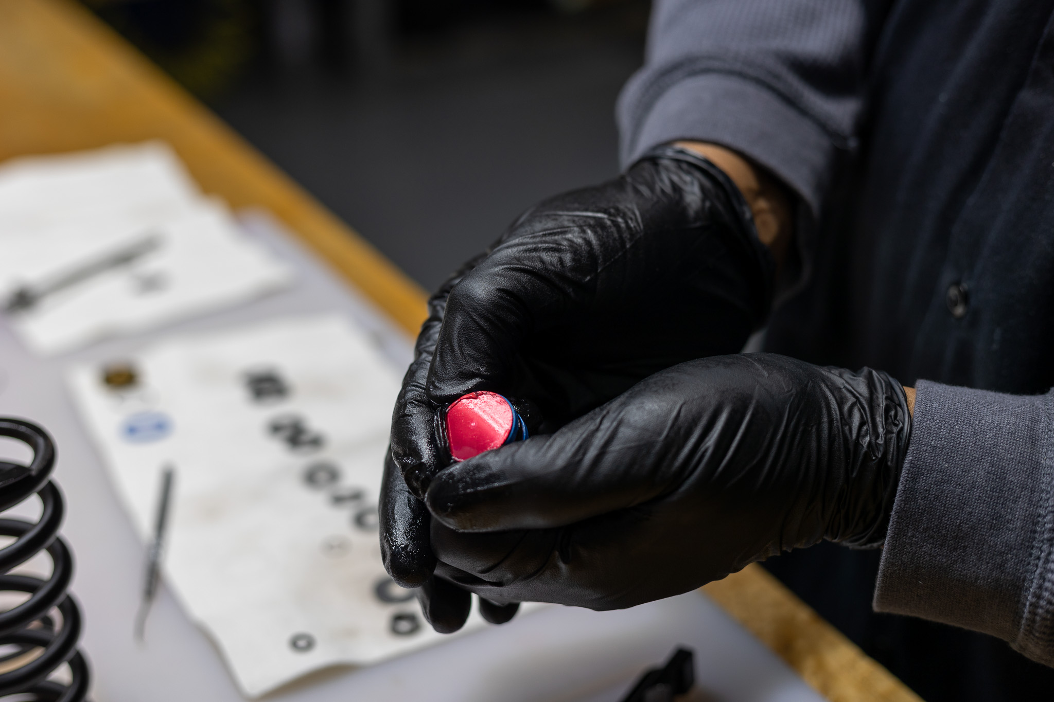
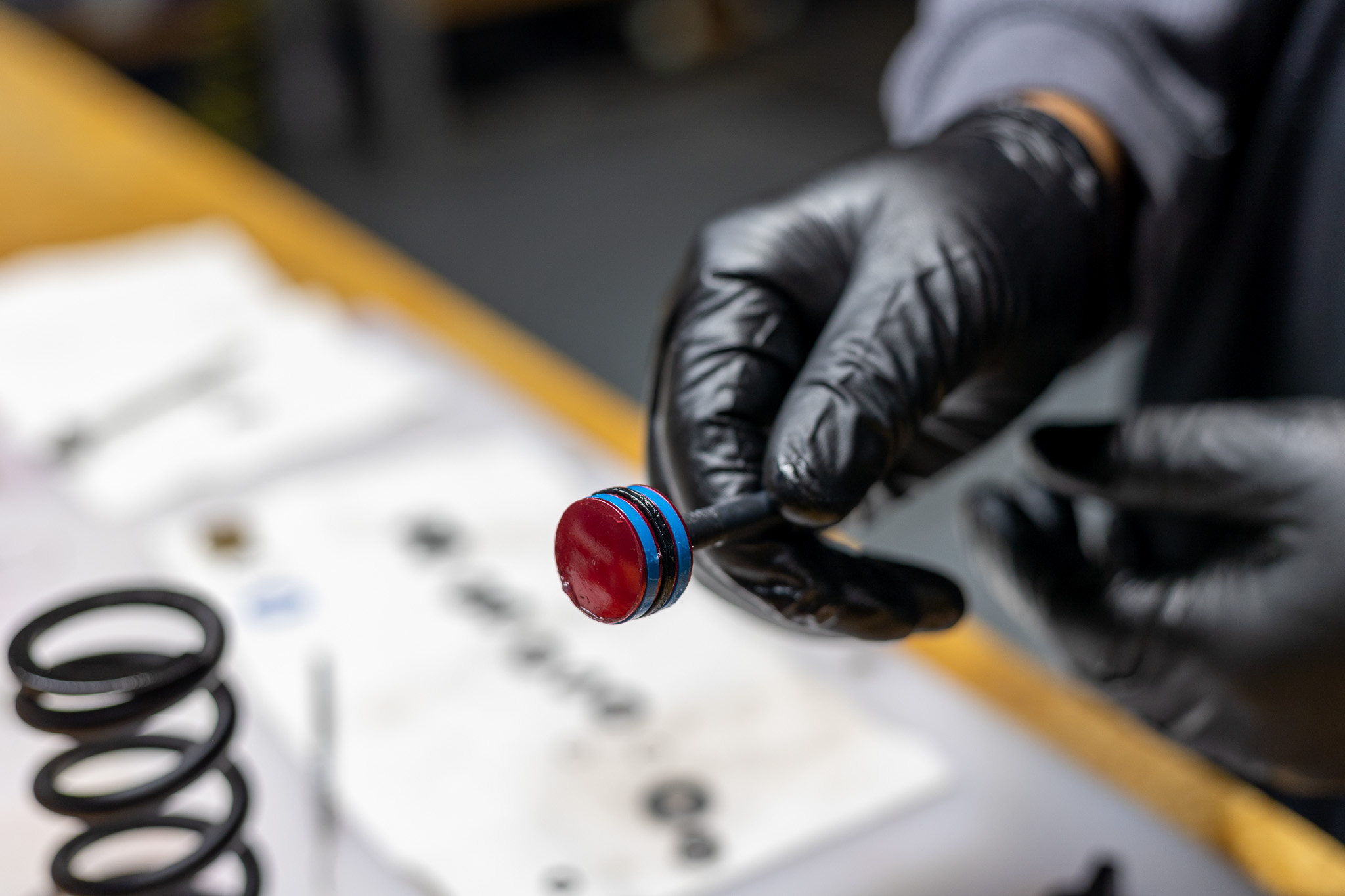
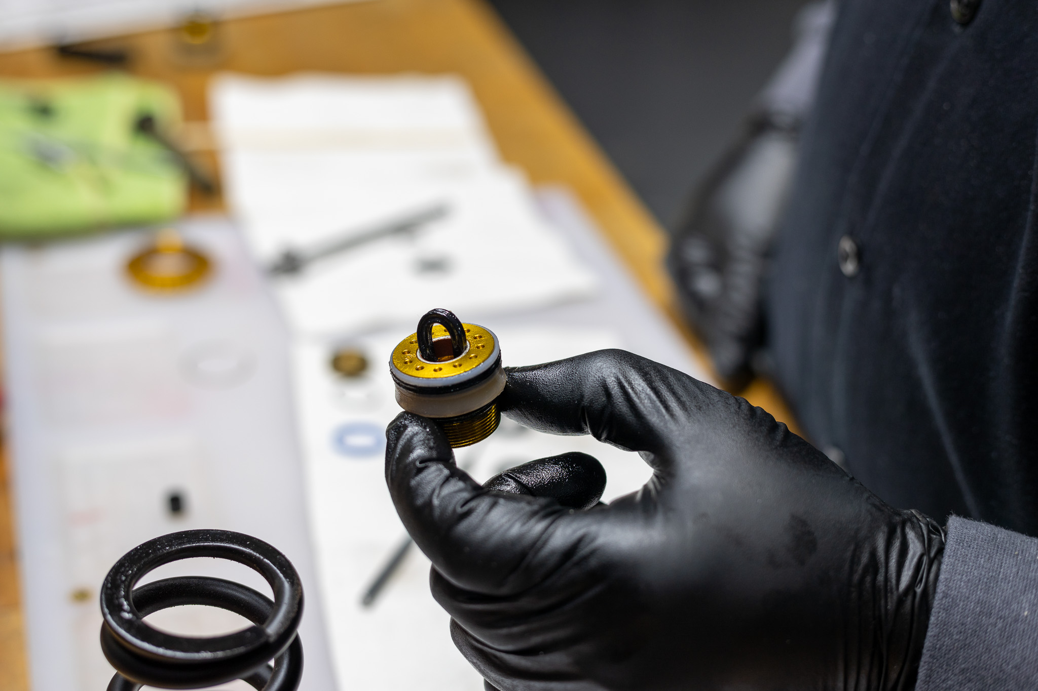
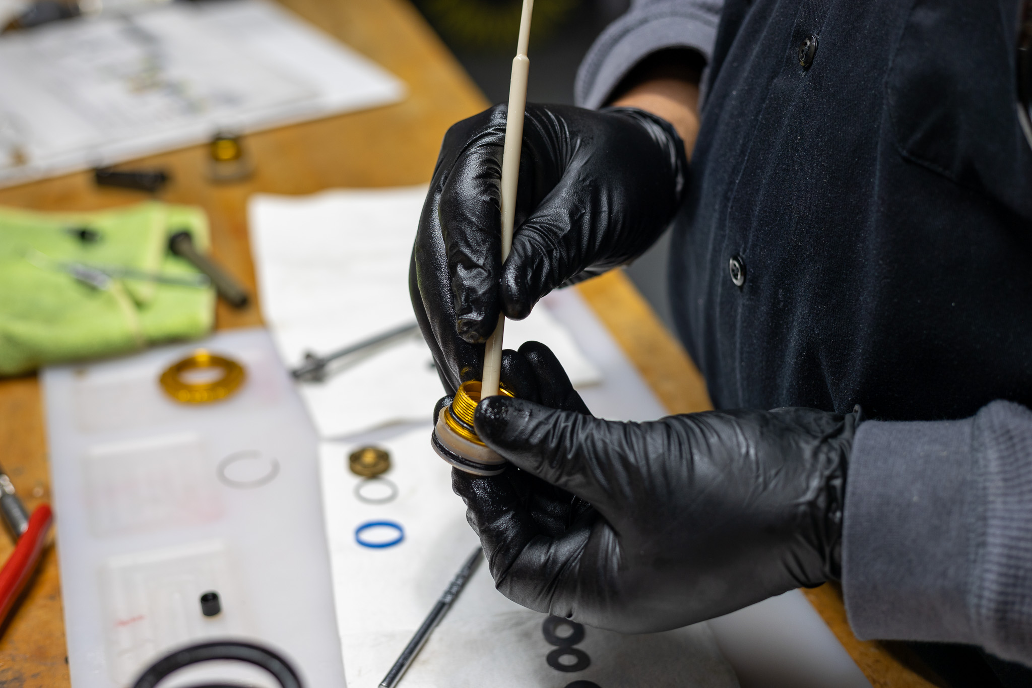
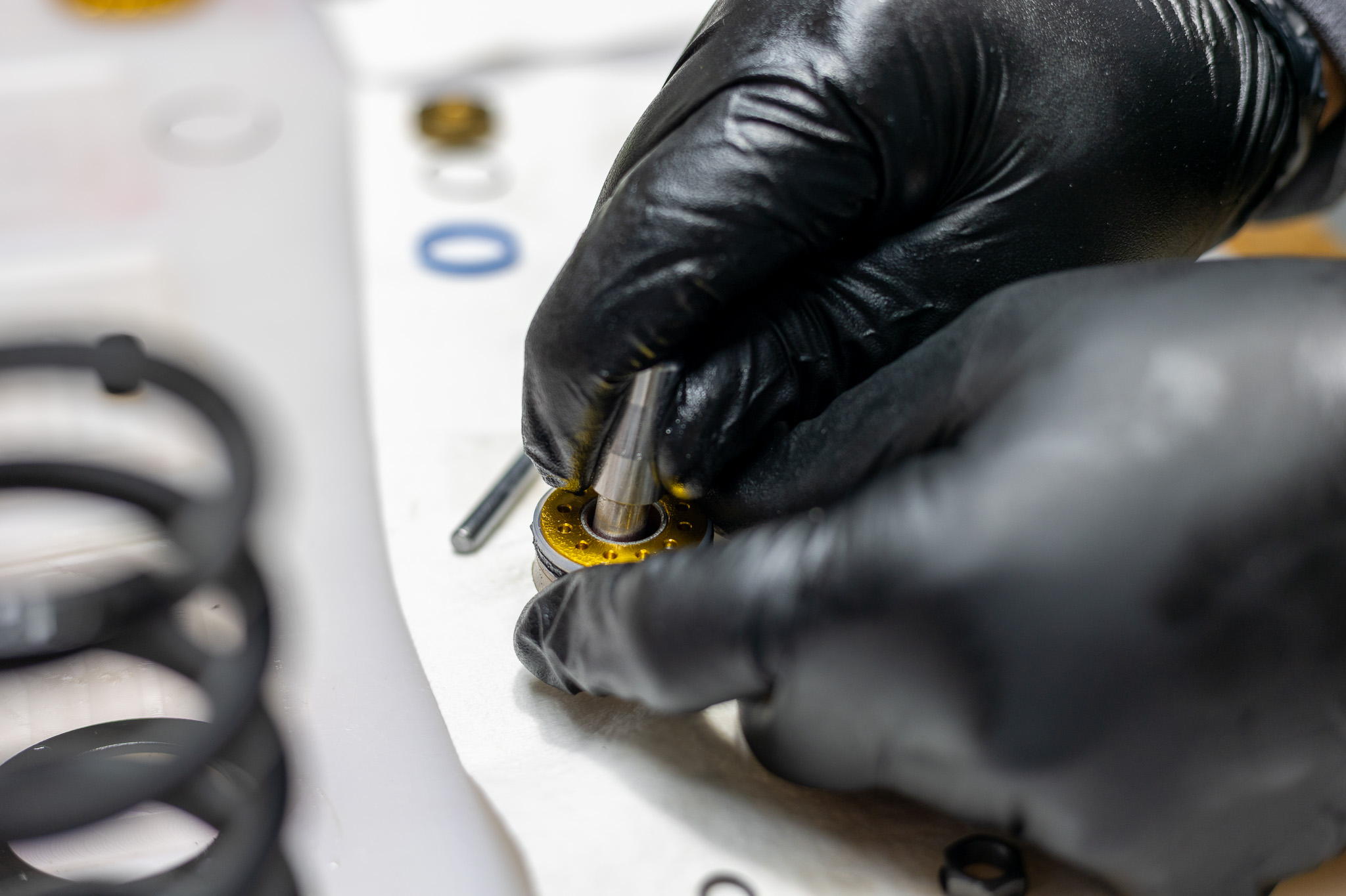
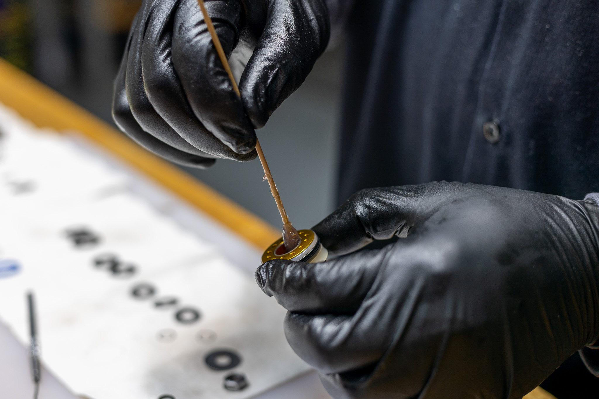
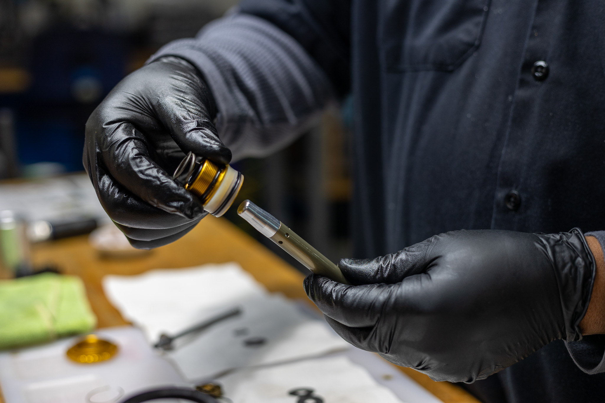
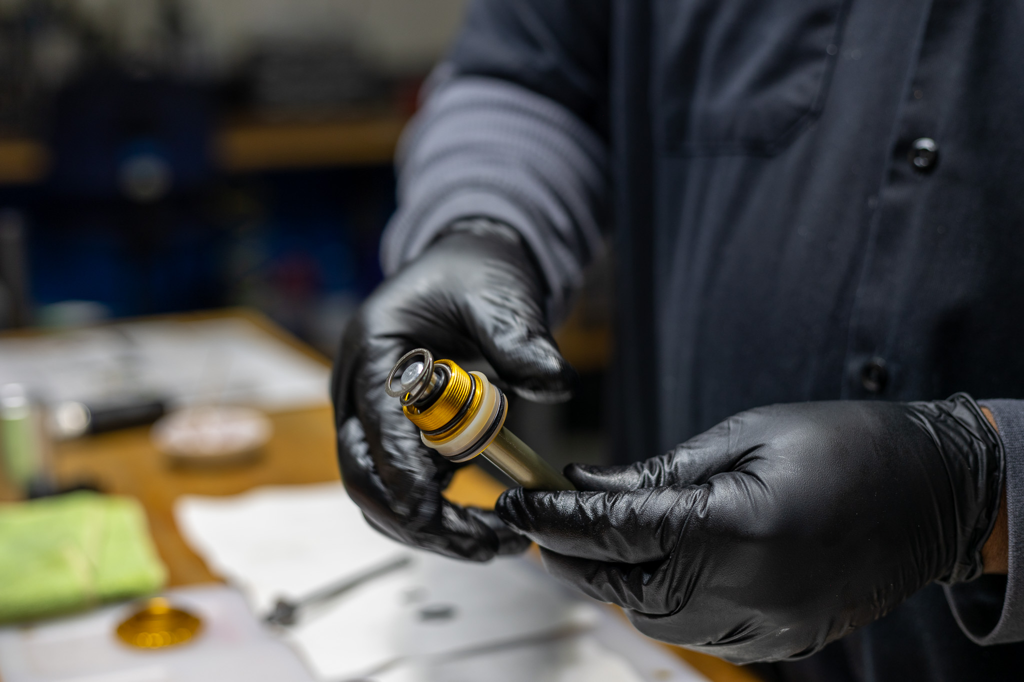
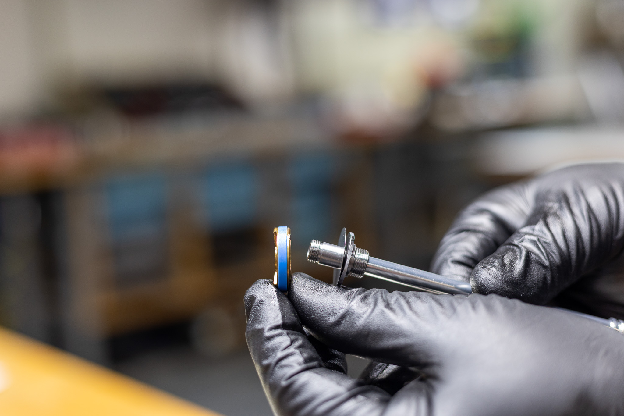
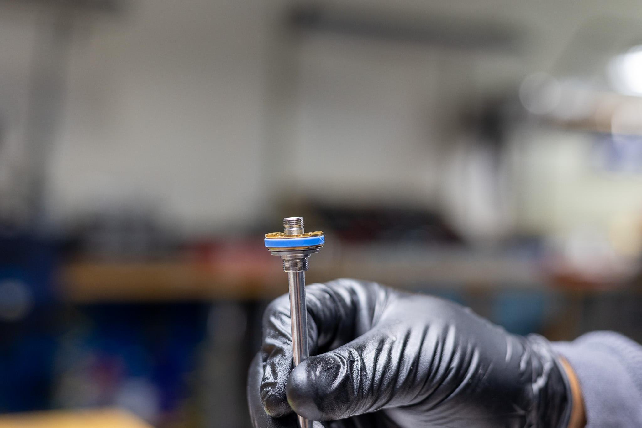
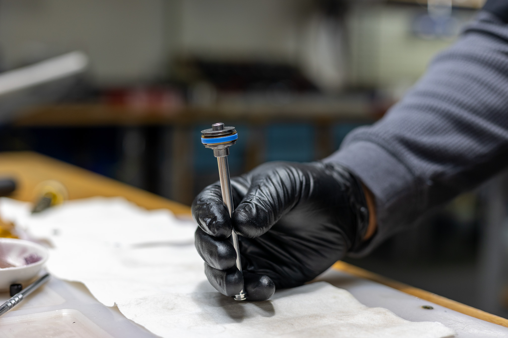
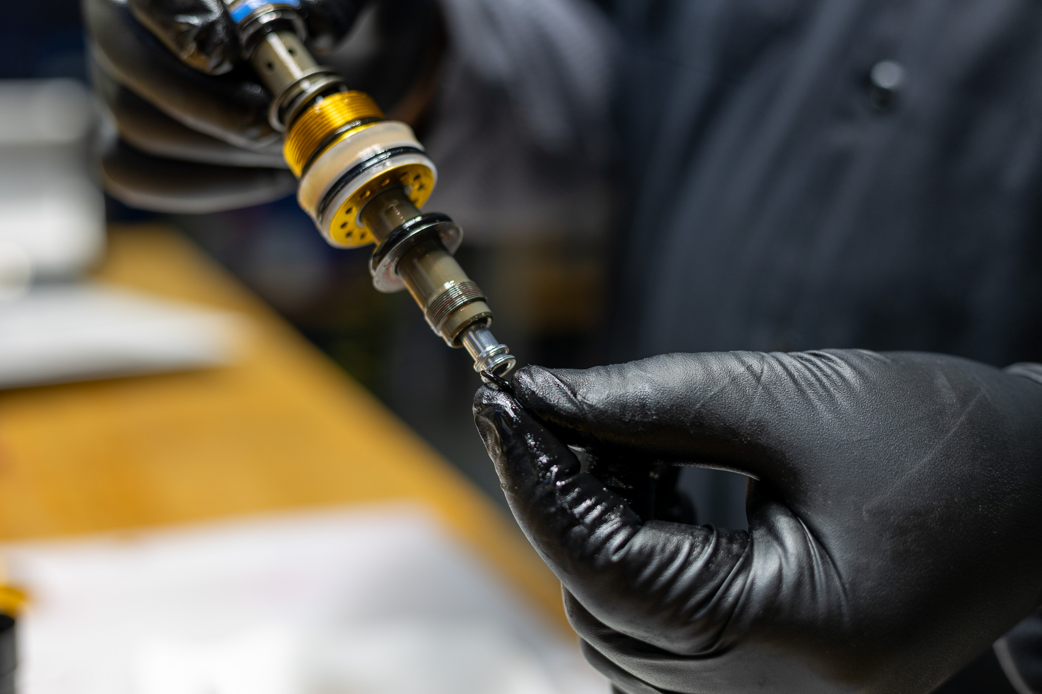
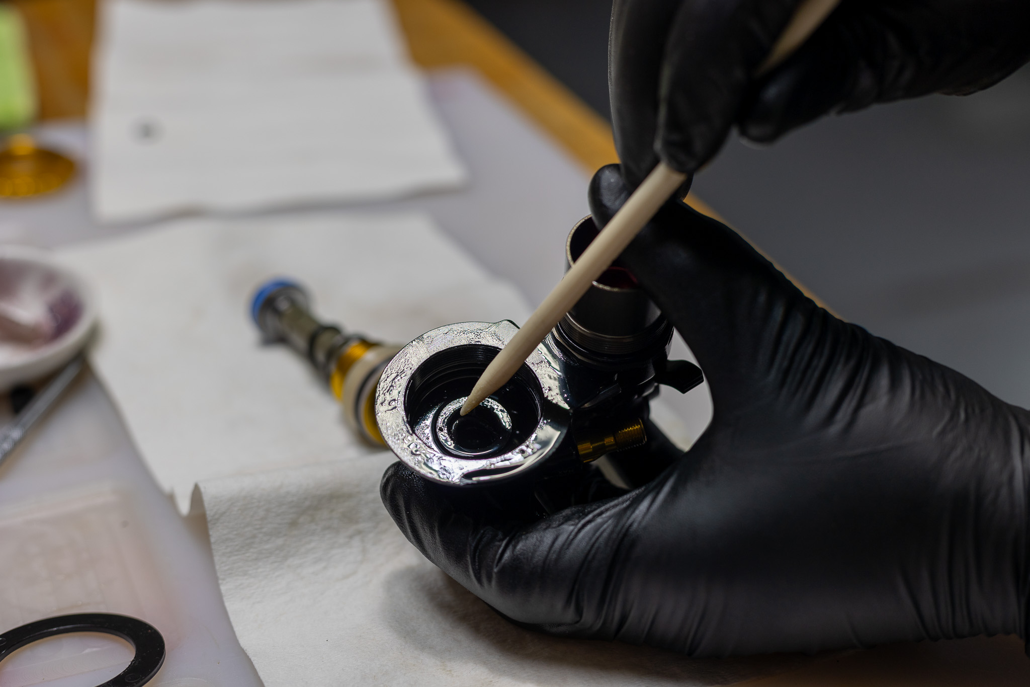
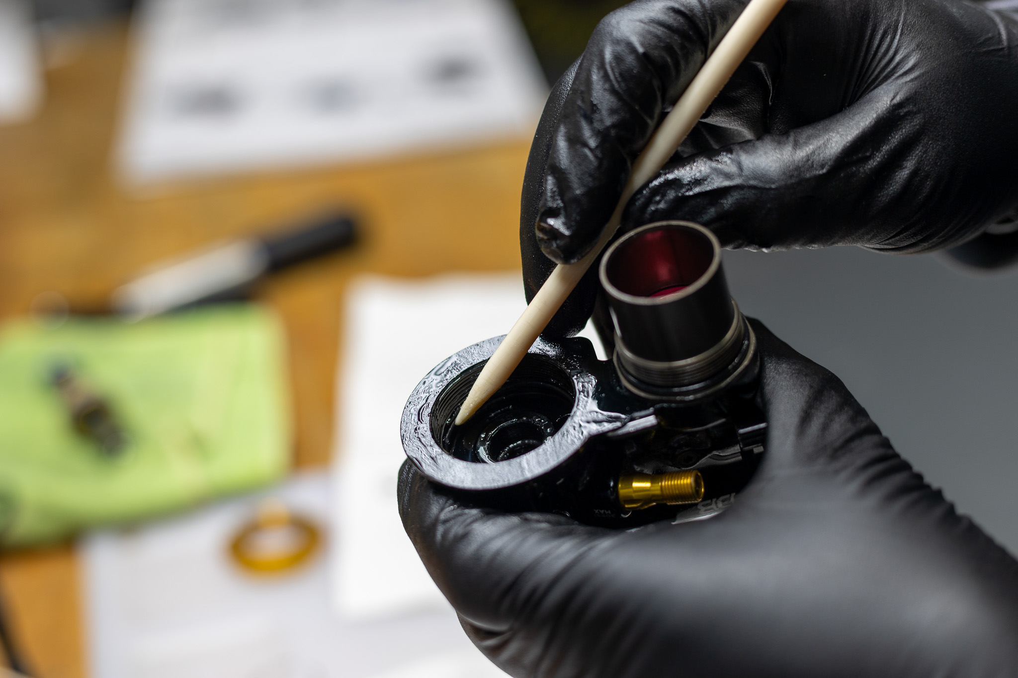
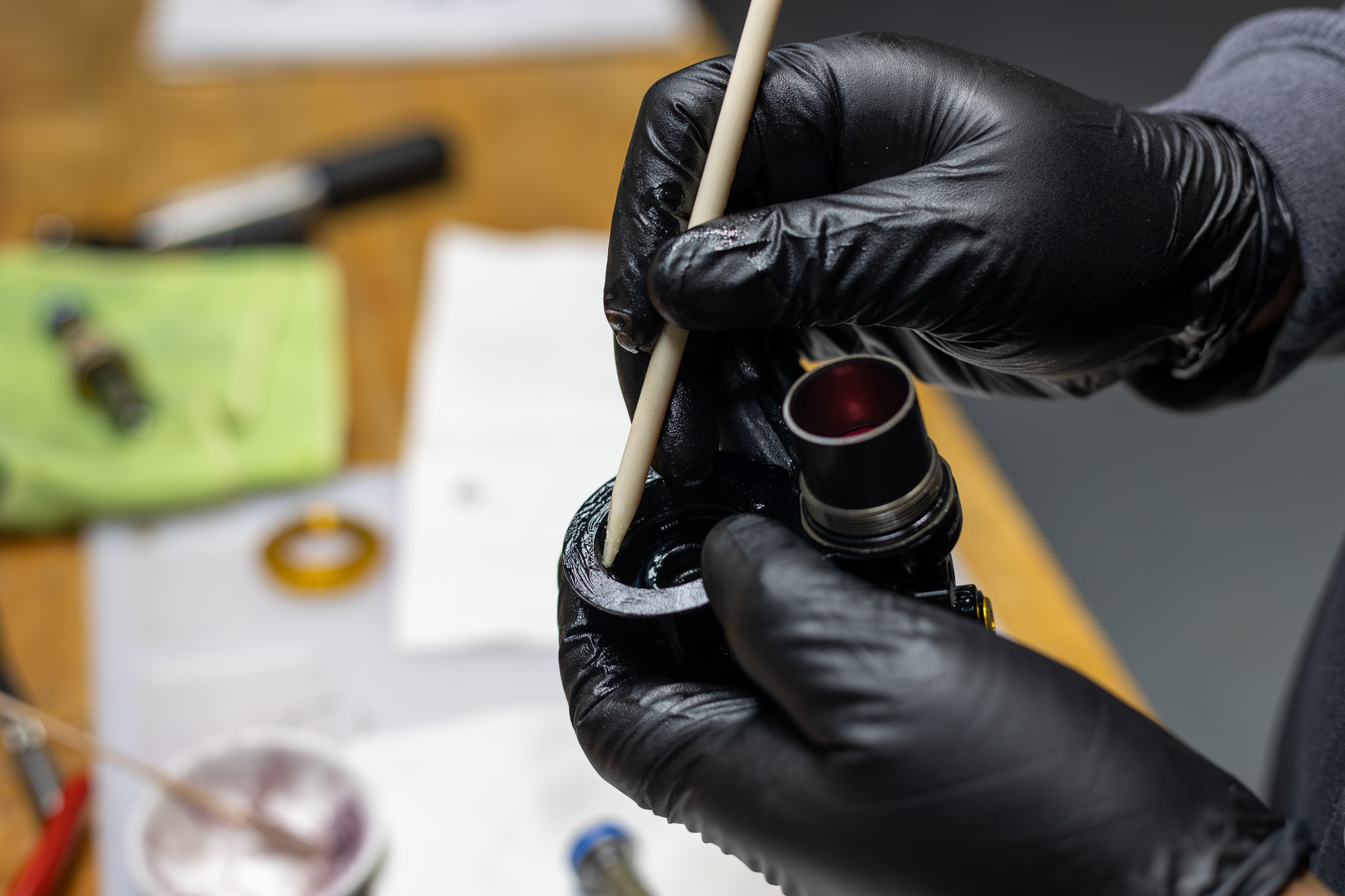
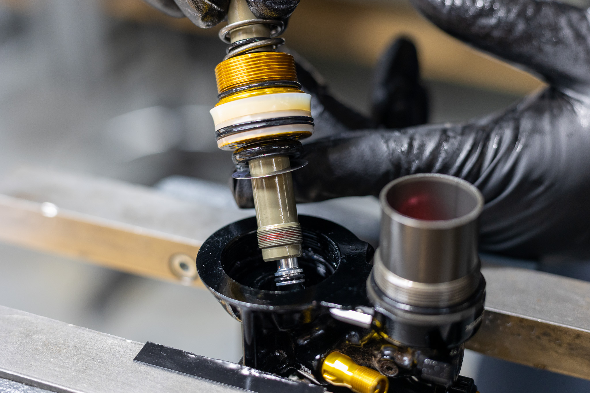
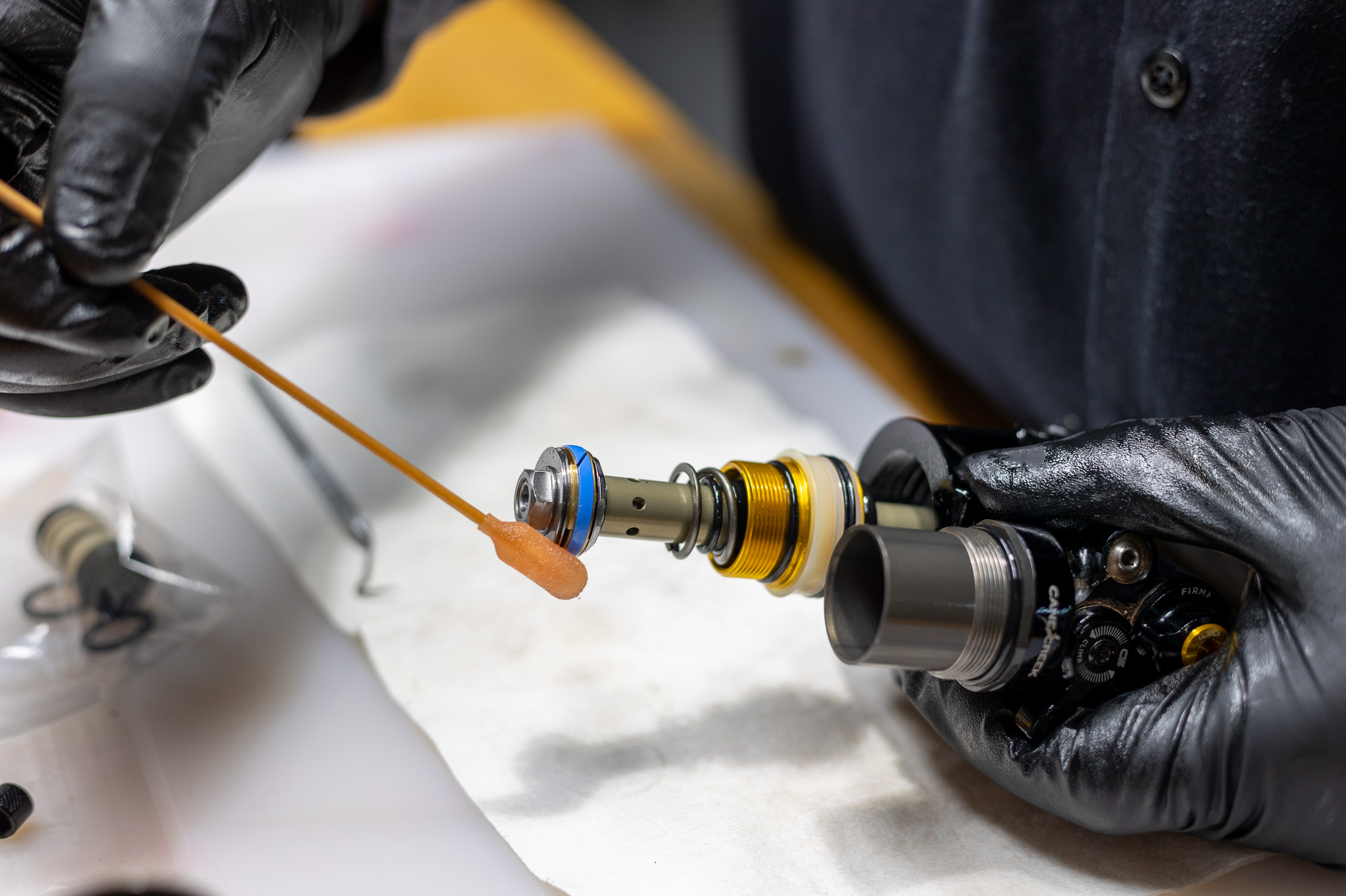
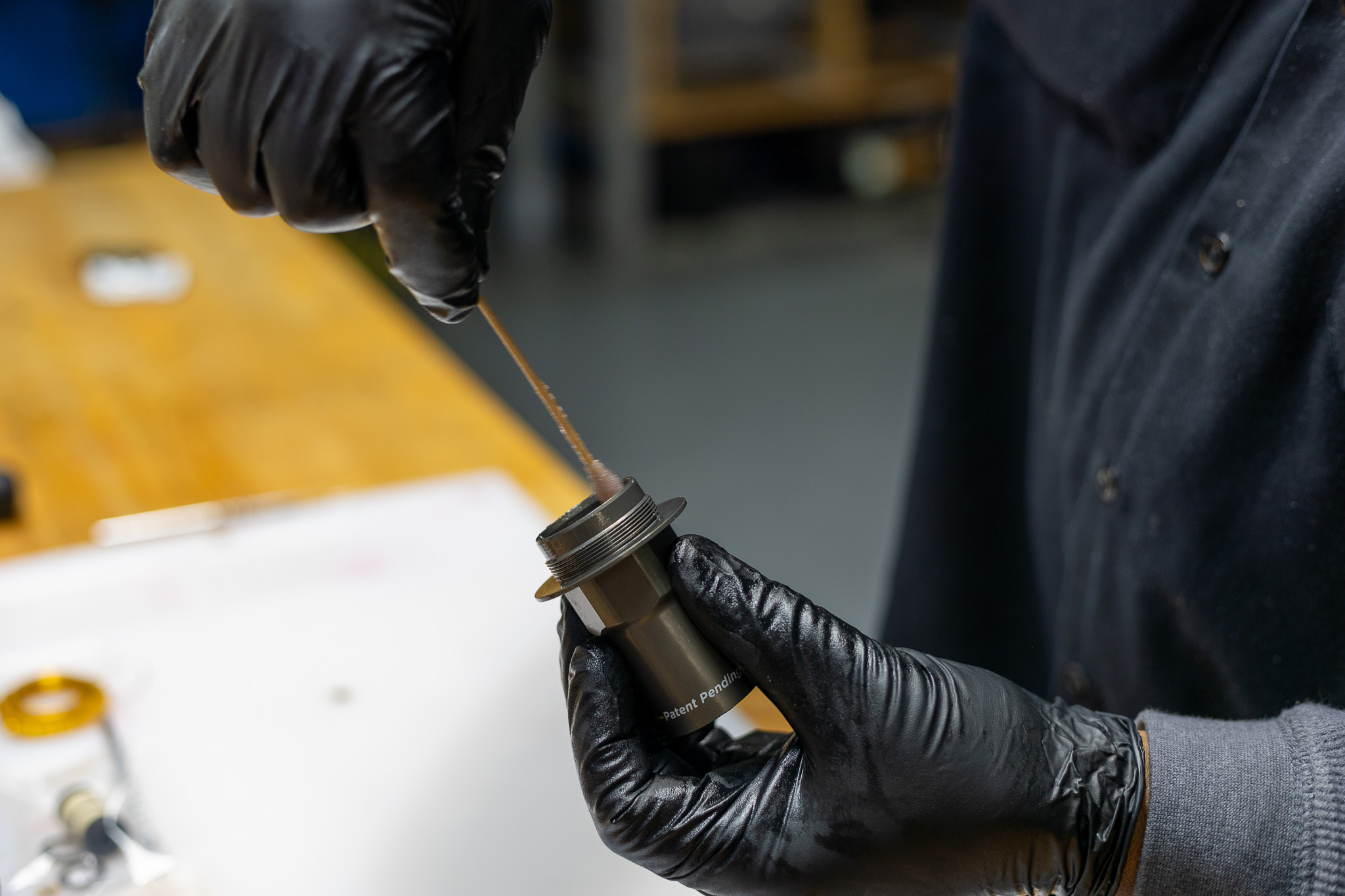
100 hour service – Thoroughly grease and install inner (ADD0129) & outer (ADD0138) quad rings and o-ring (AAD0771) on oil seal head. Inner quad ring will require Shaft Seal Head Bullet (ADD0327).
200 hour service – Thoroughly grease outer inner quad ring on new oil seal head (ADD0342).
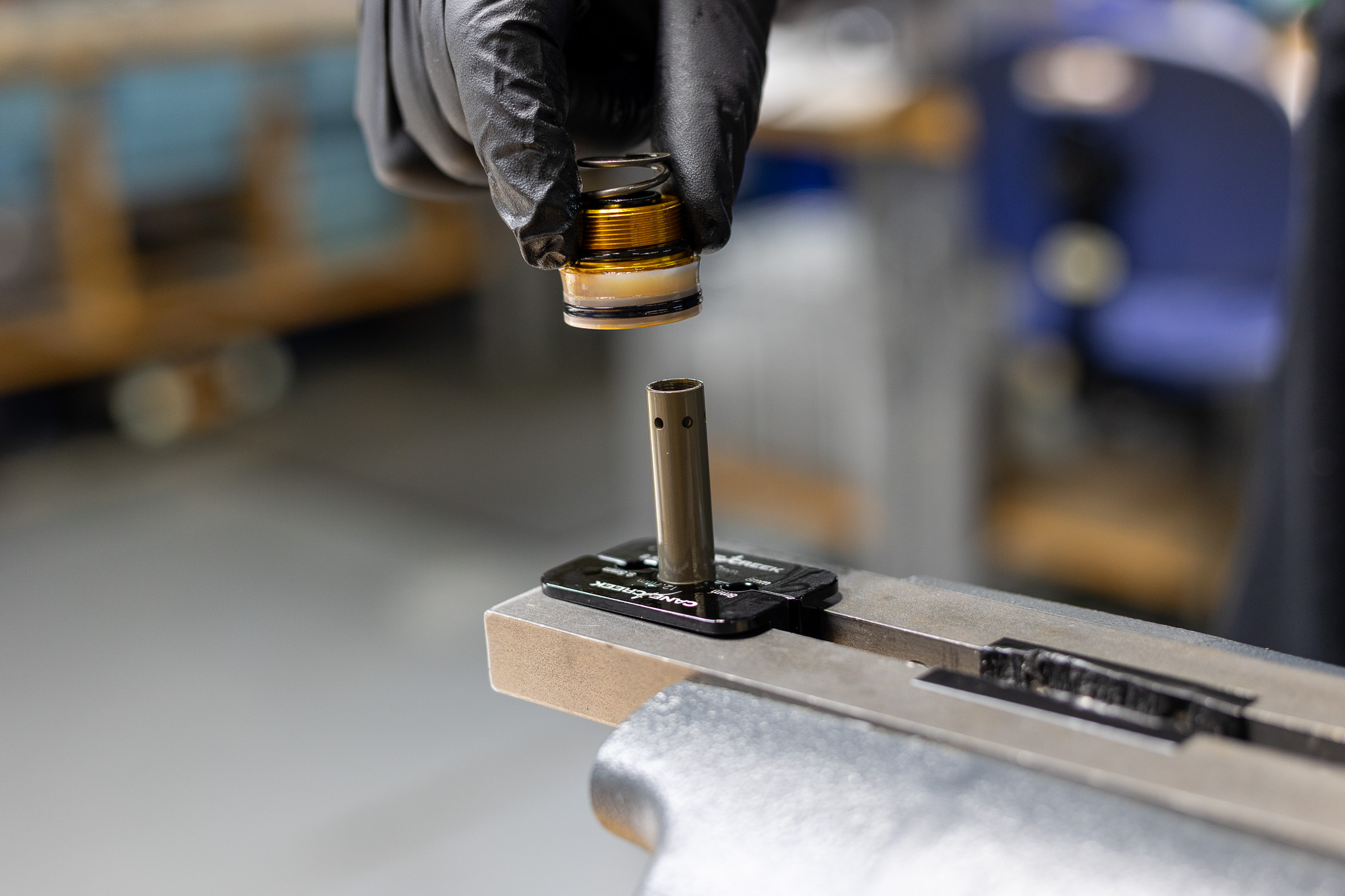
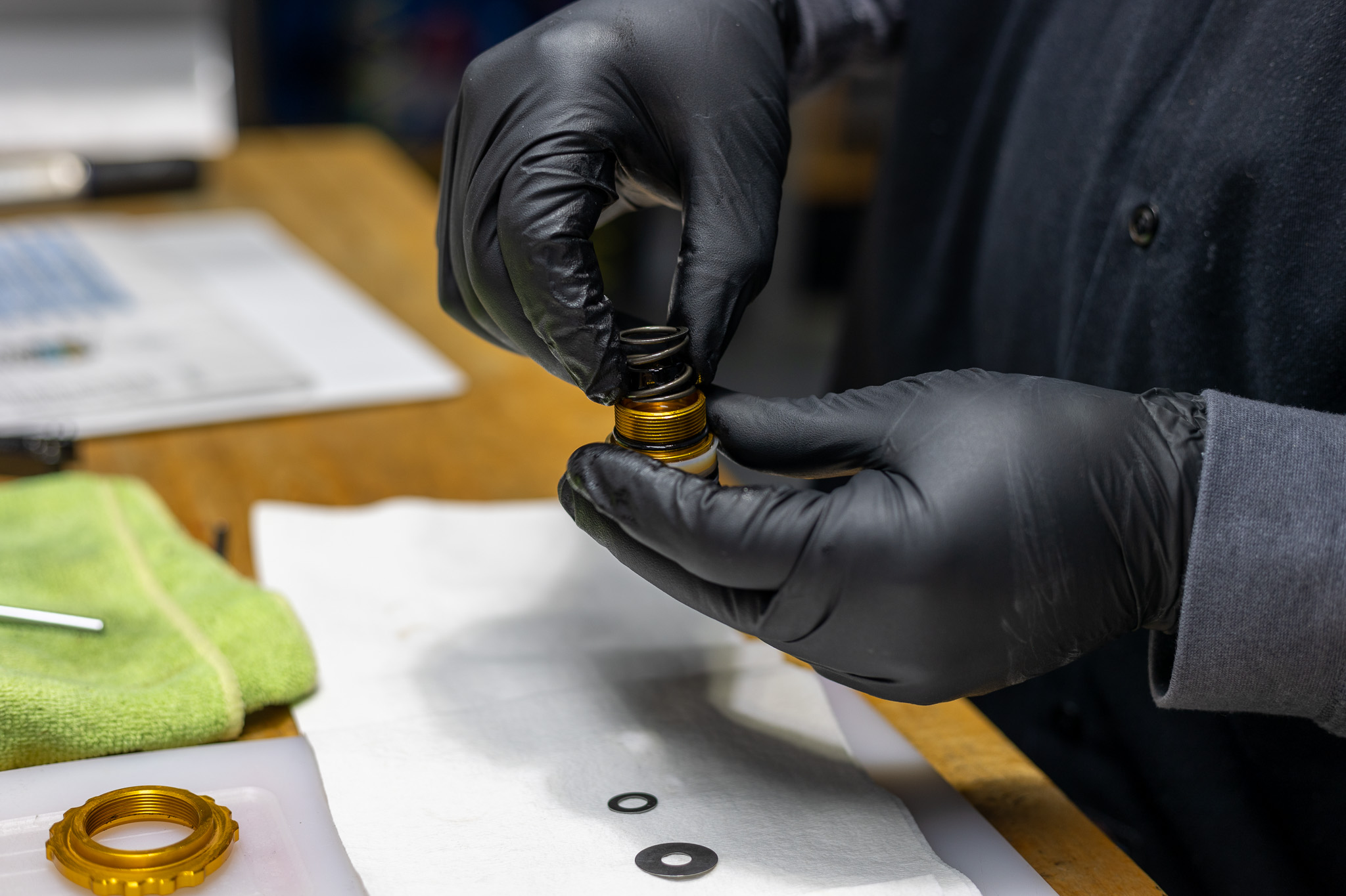
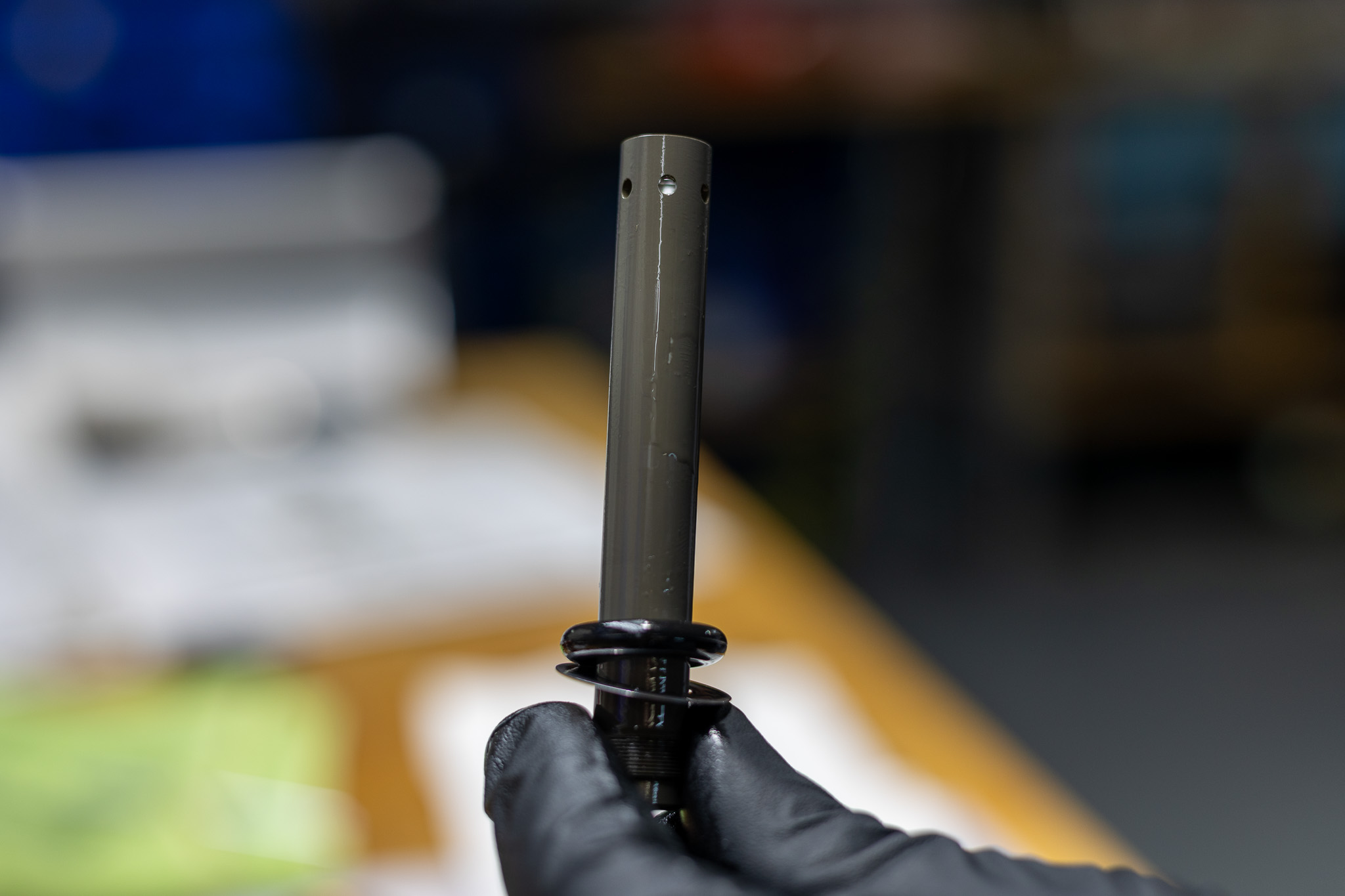
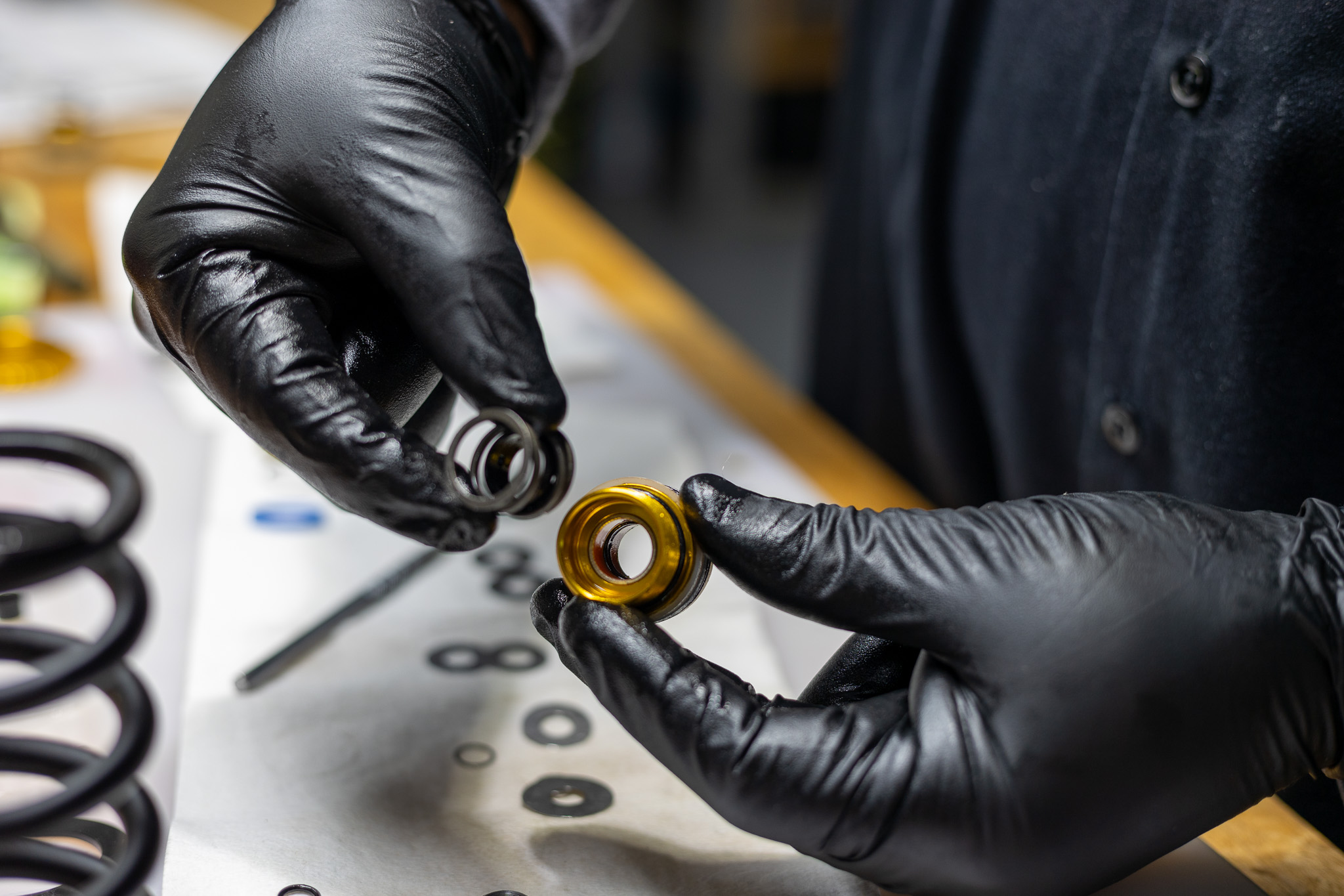
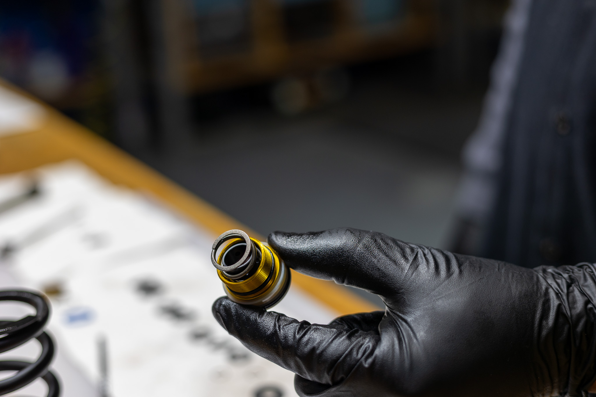
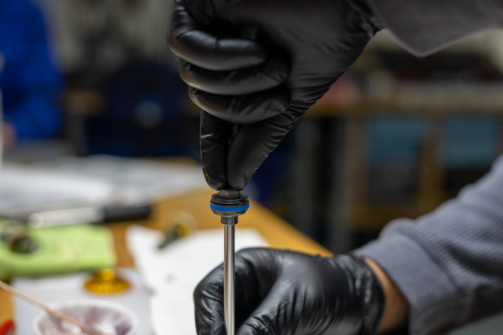
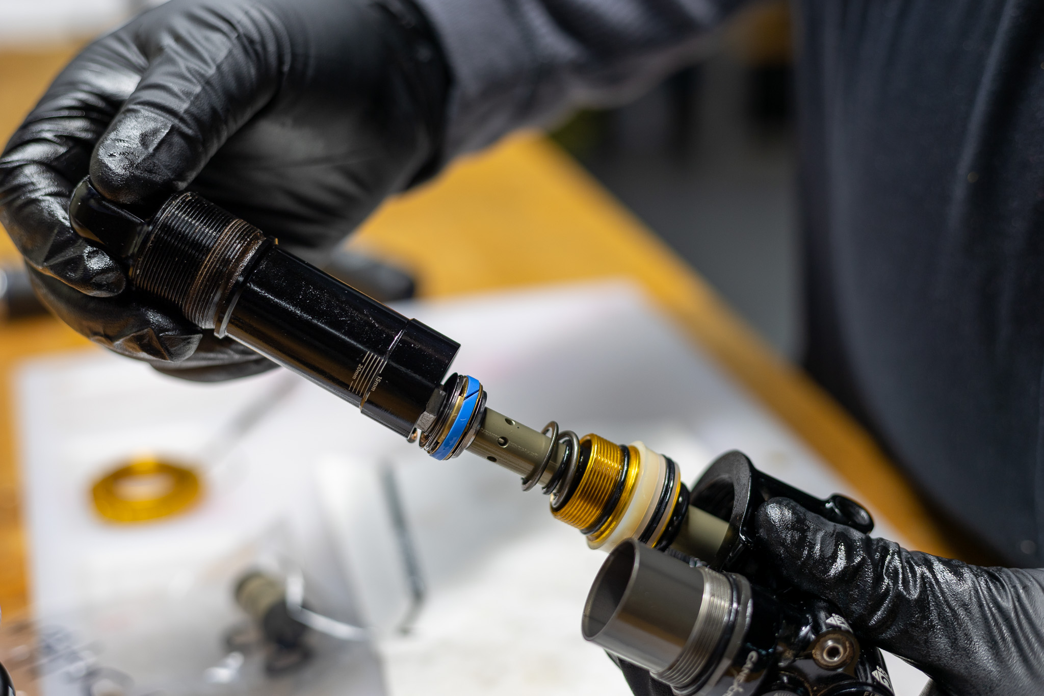
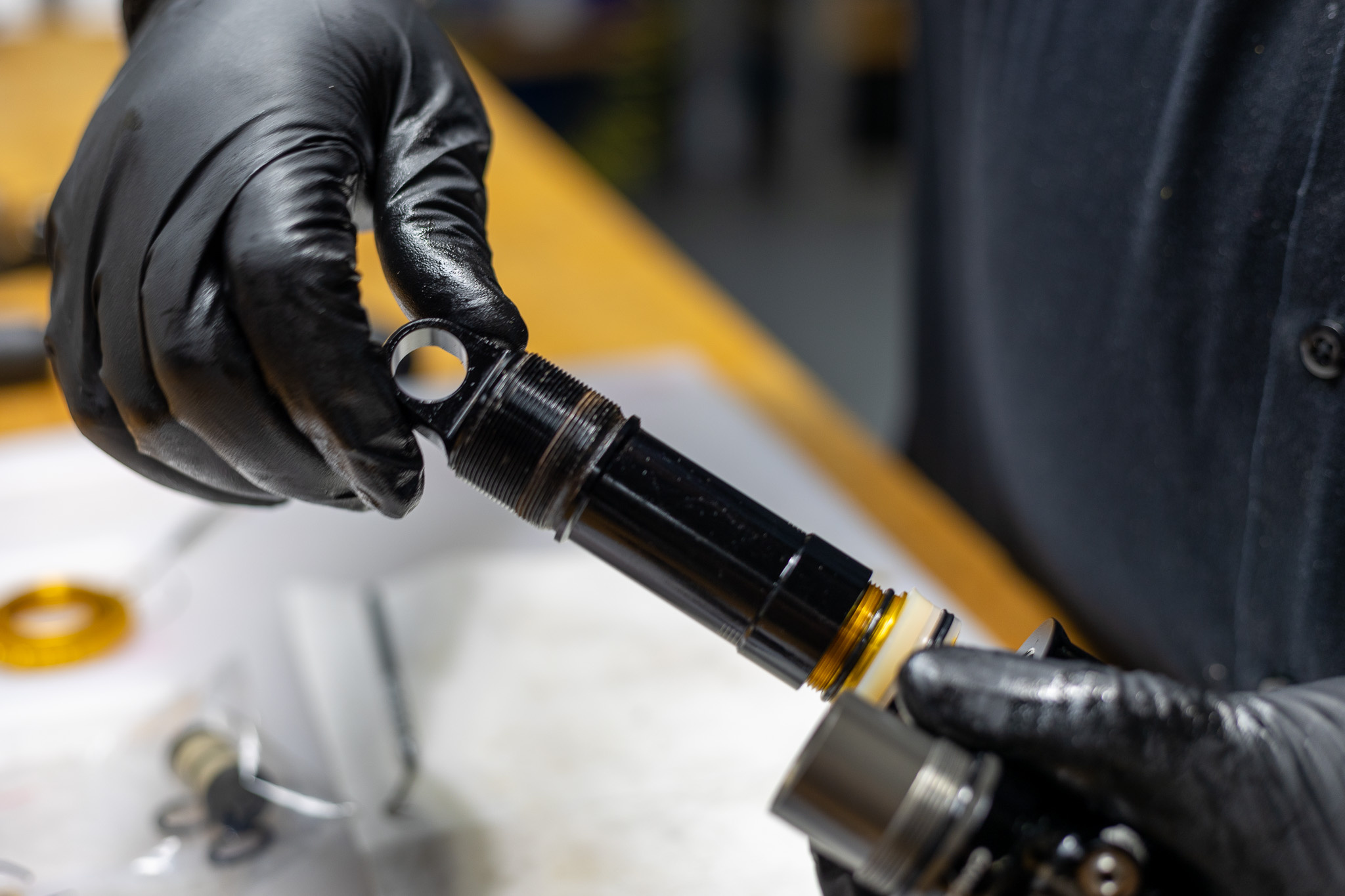
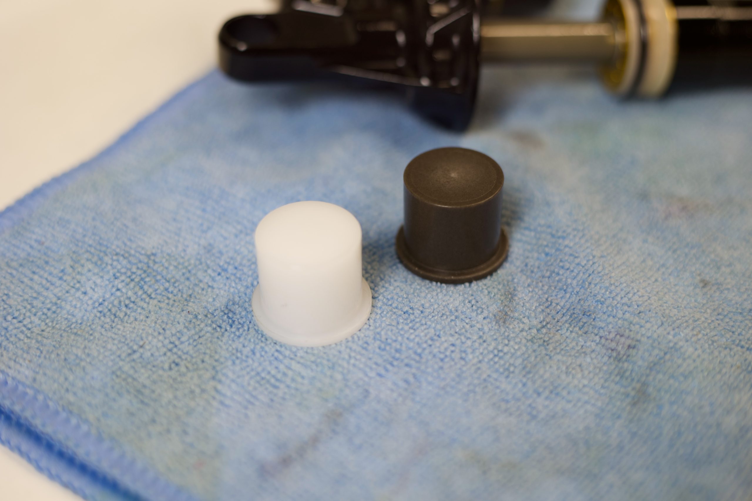
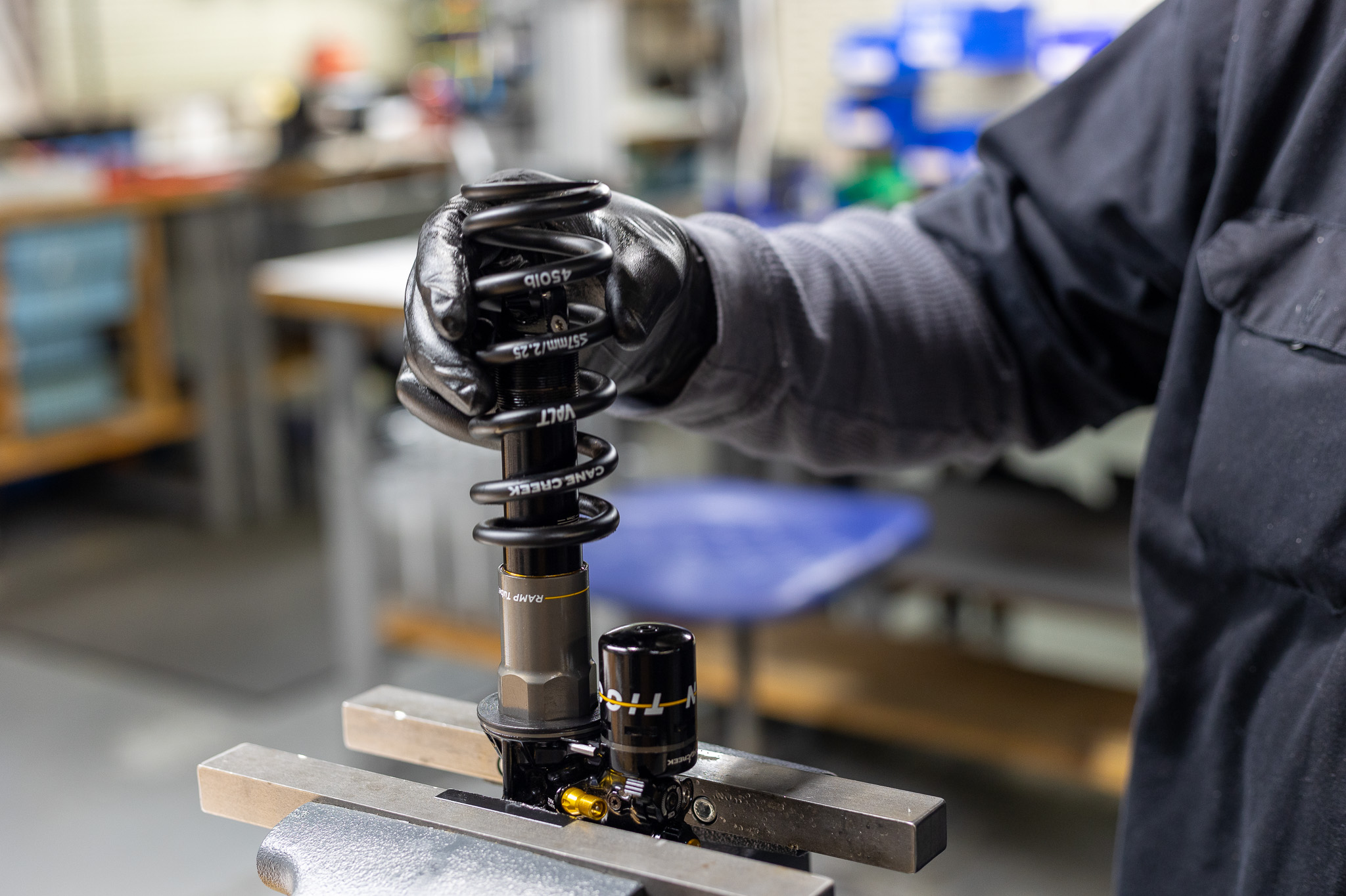
Both – Install spring and sleeve into oil seal head. Press on spring to seat properly.
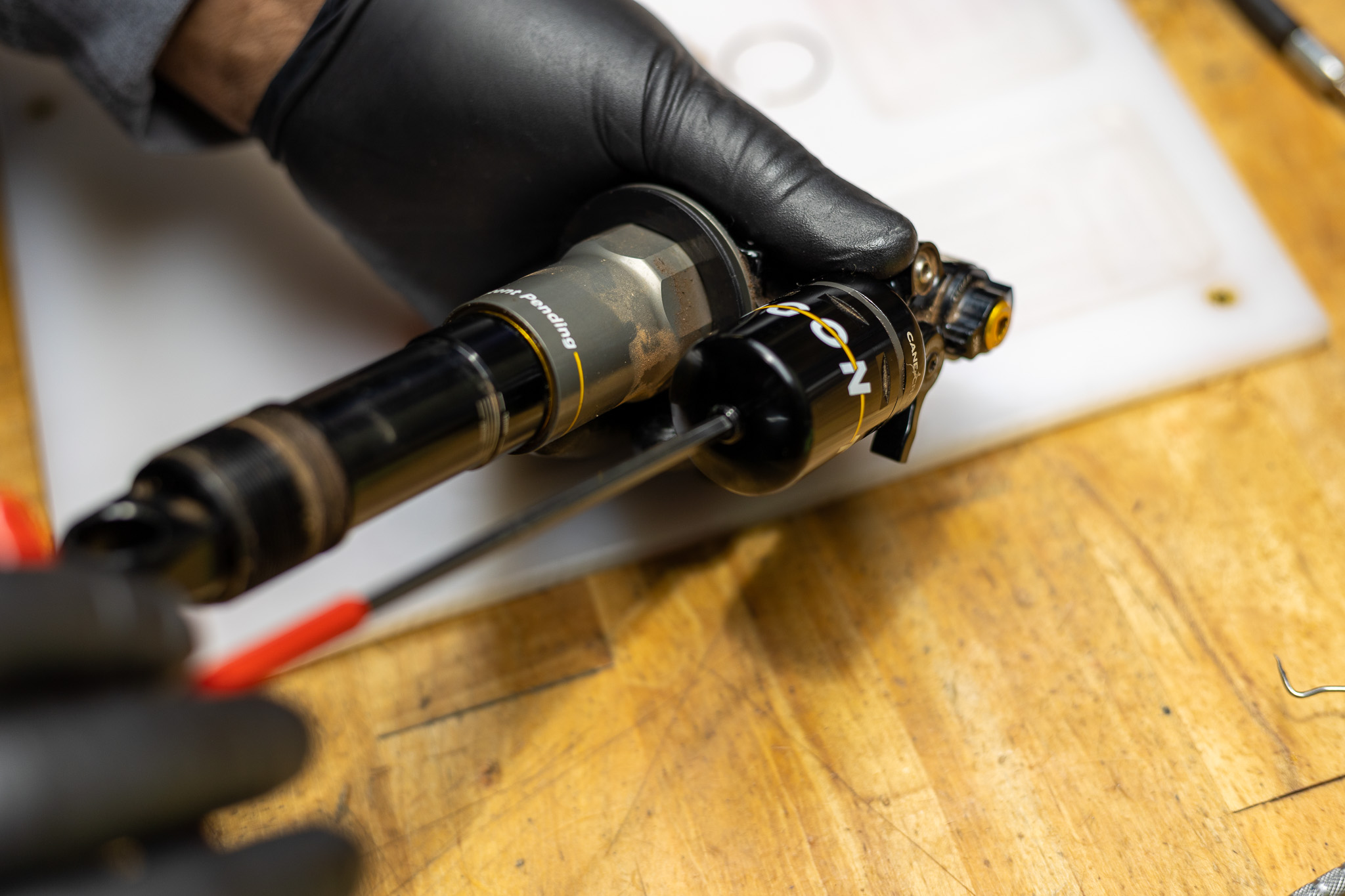
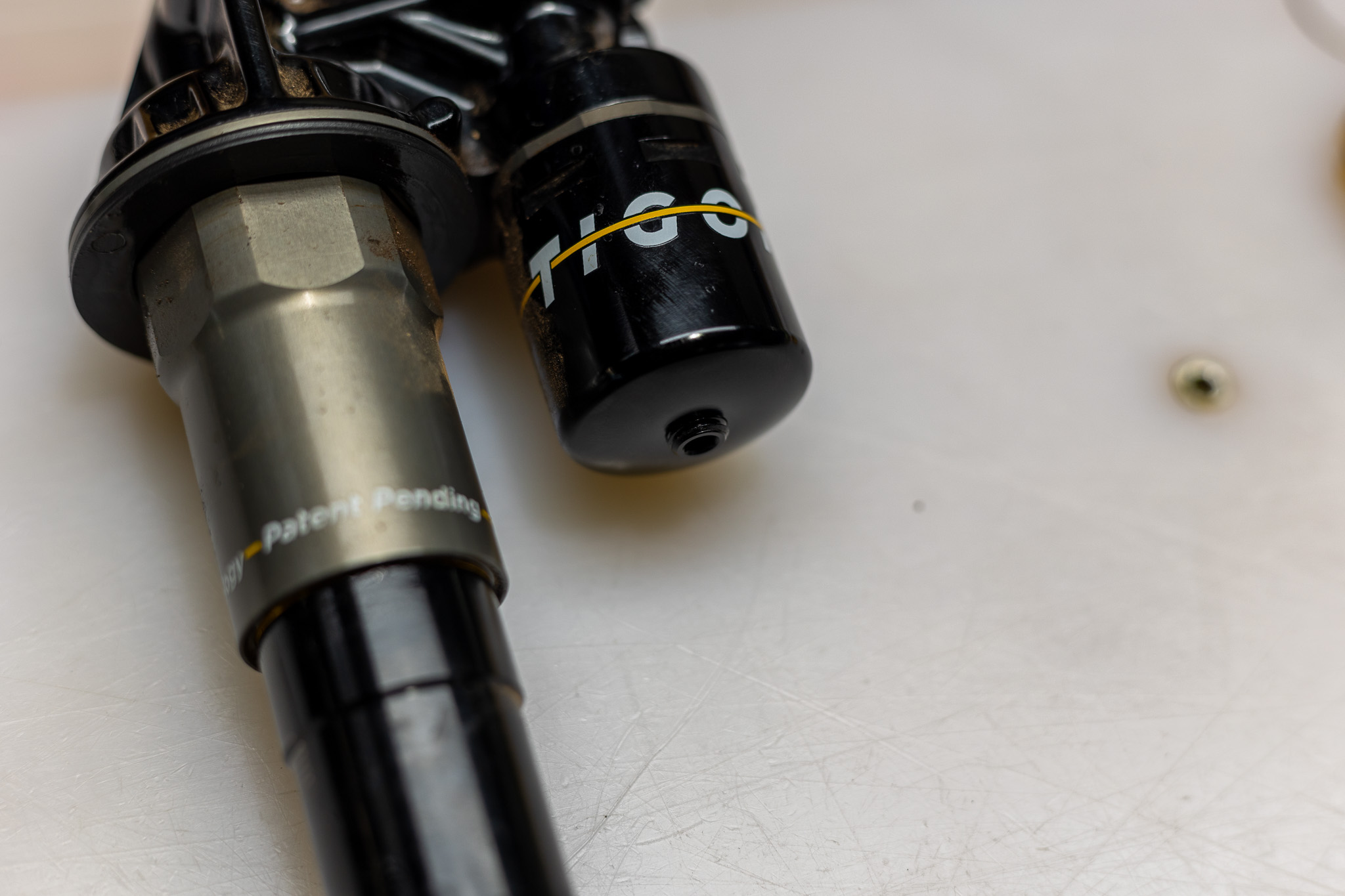
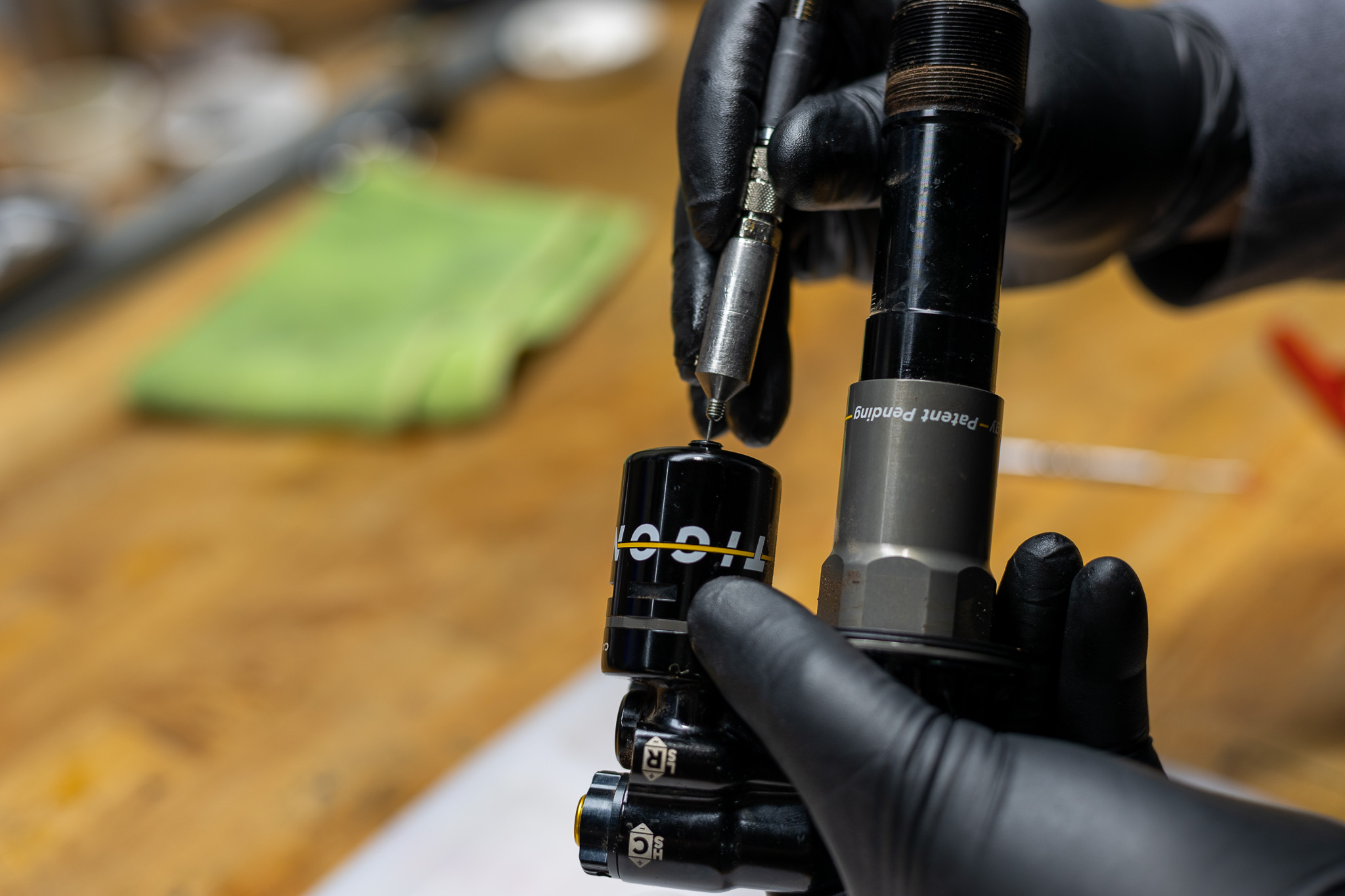
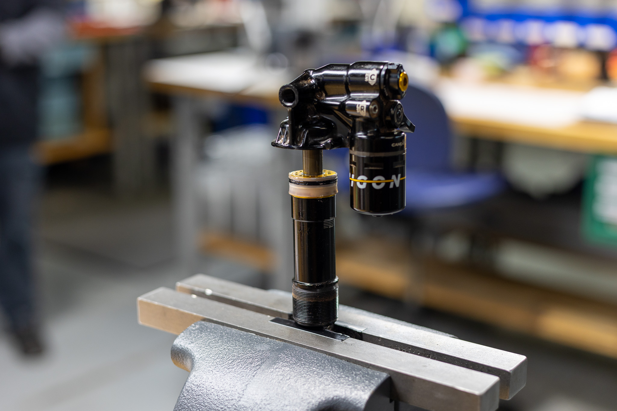
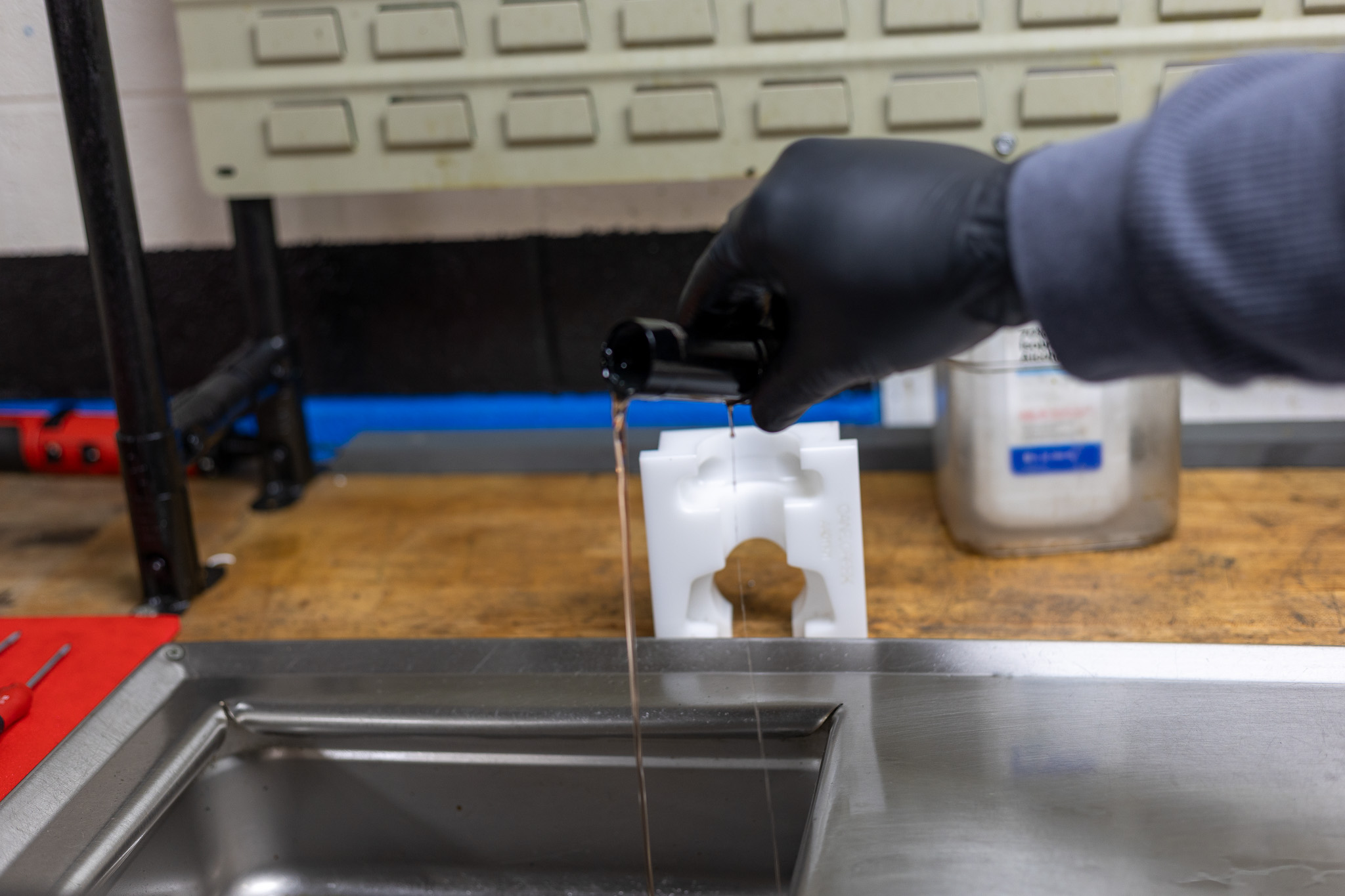
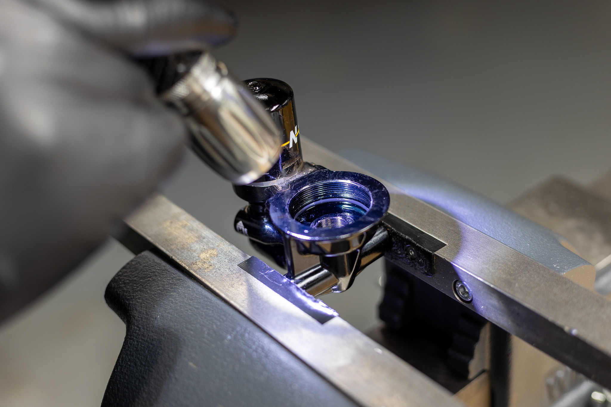
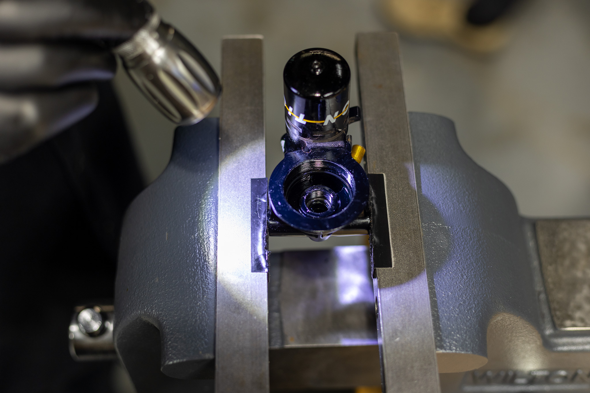
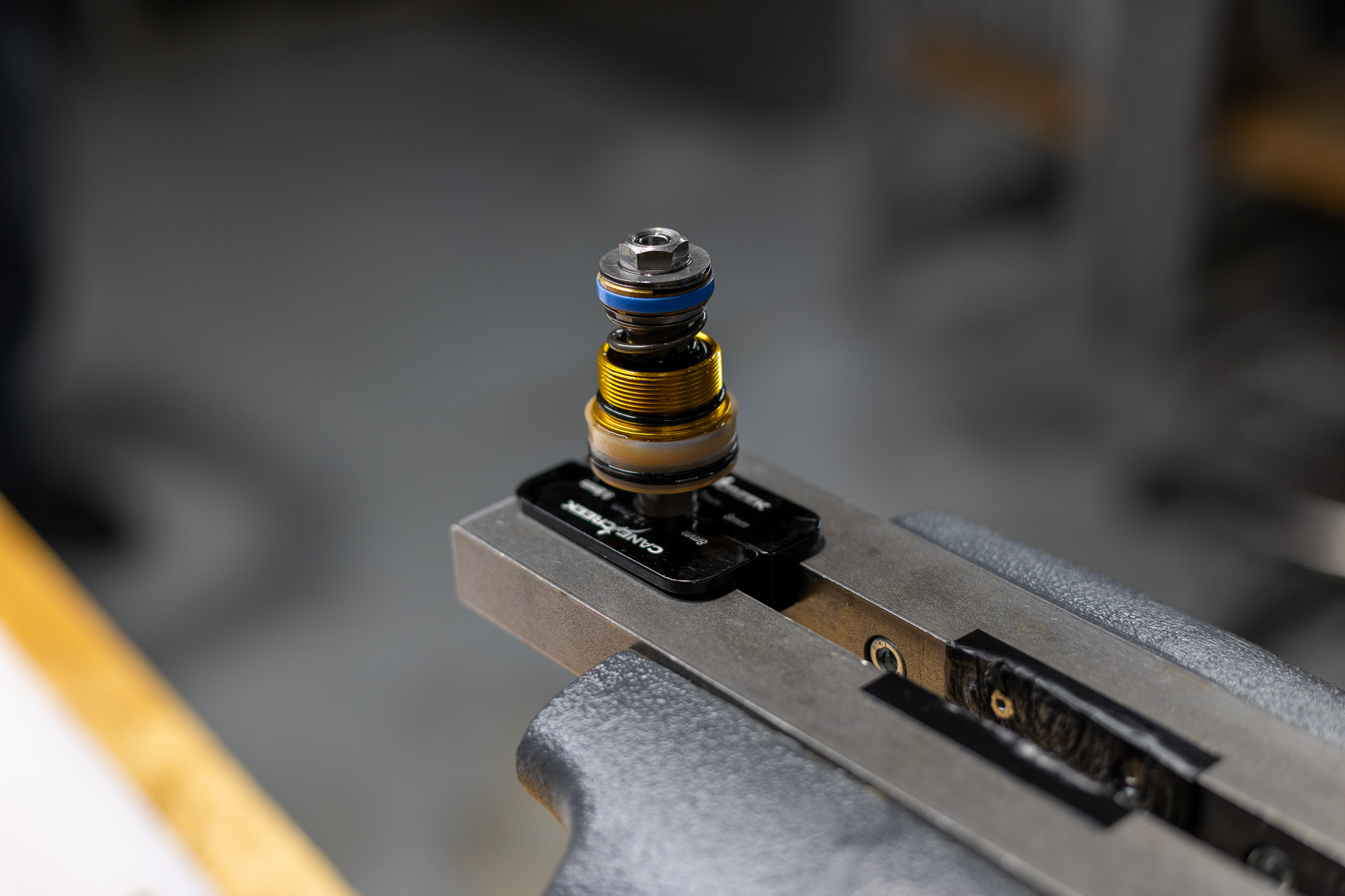
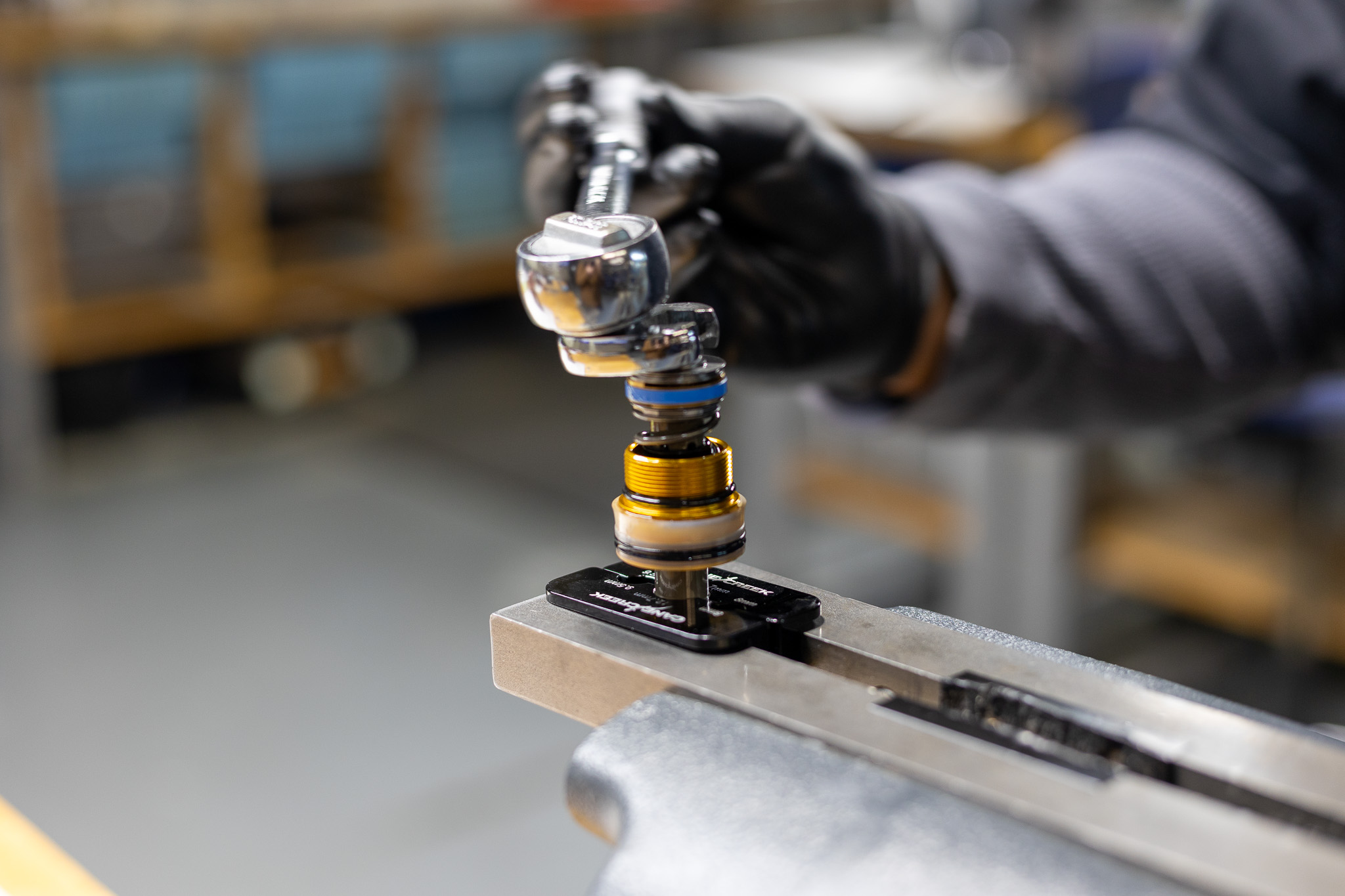
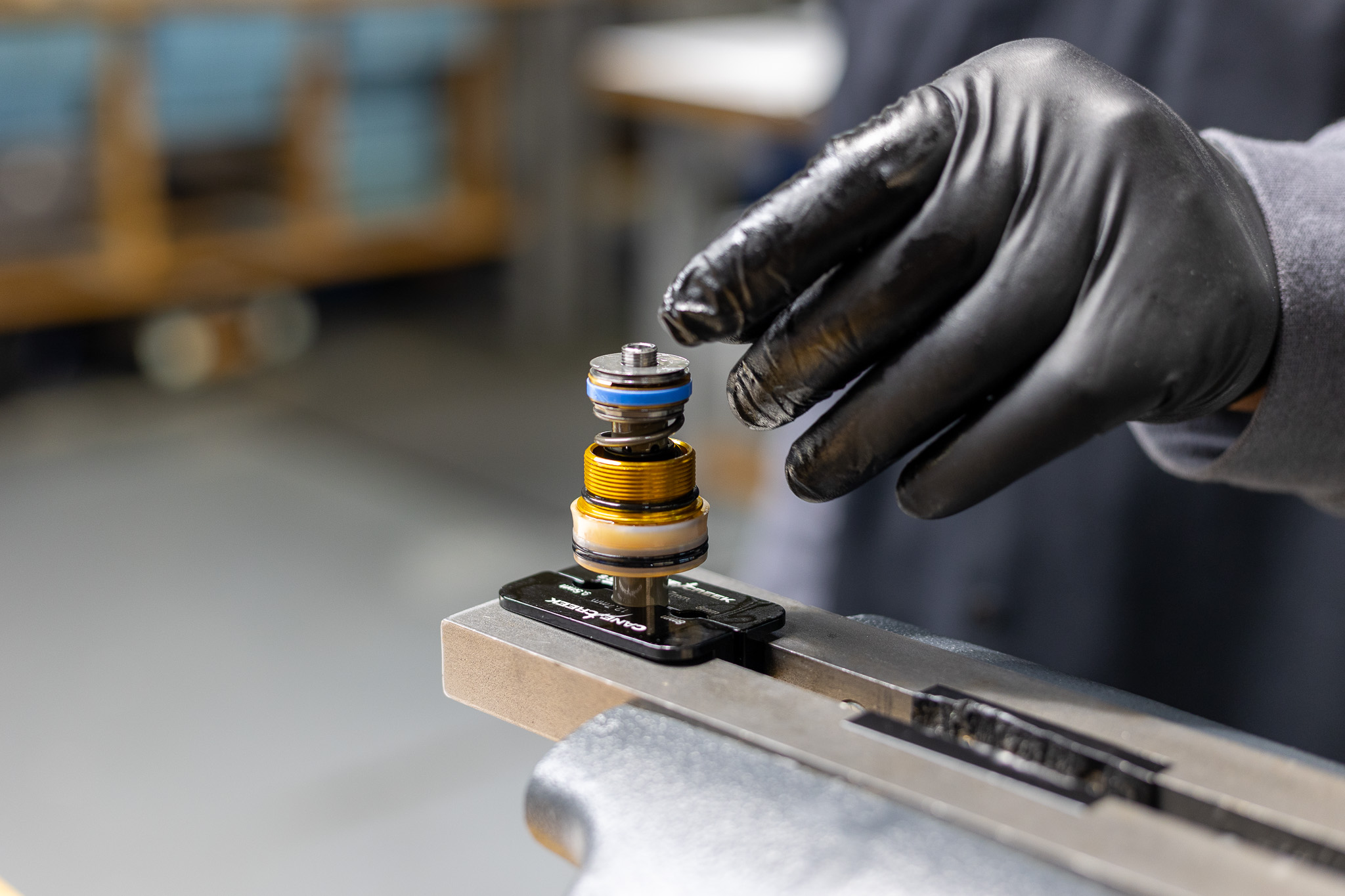
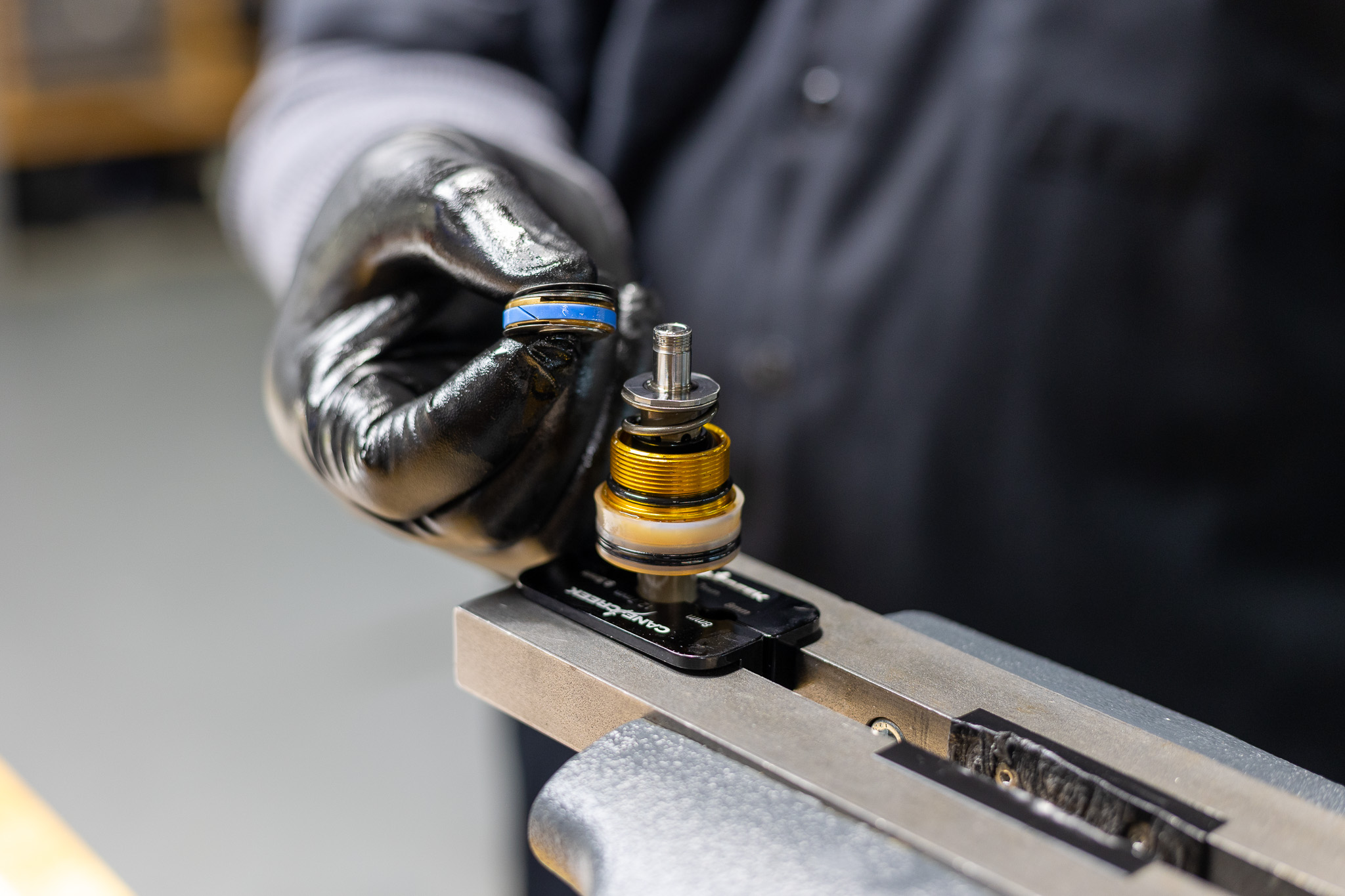
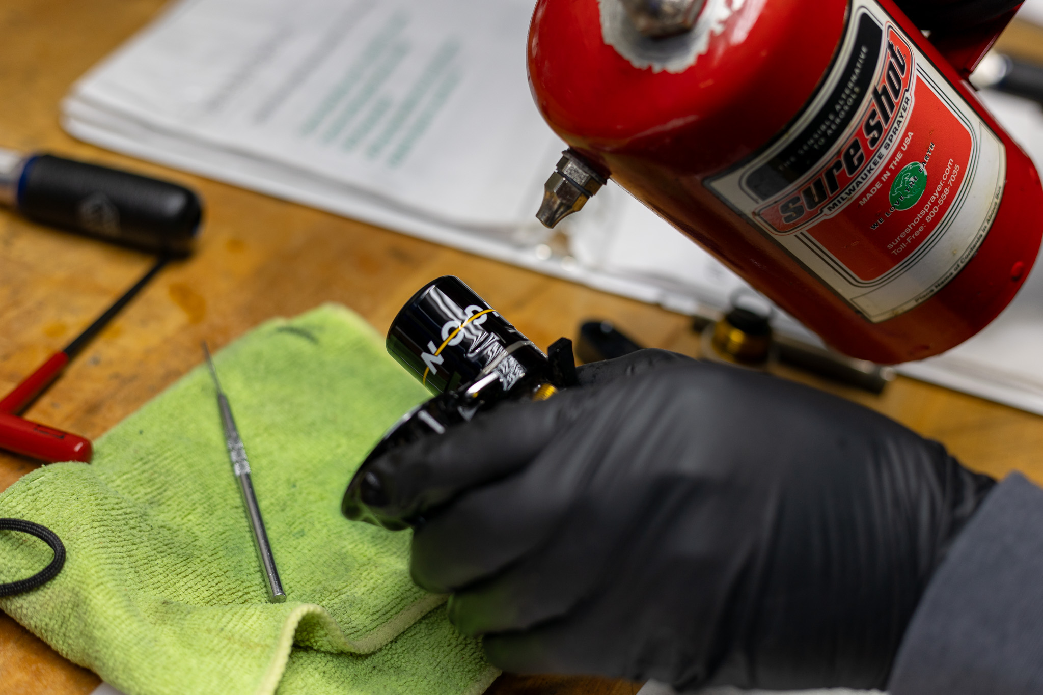
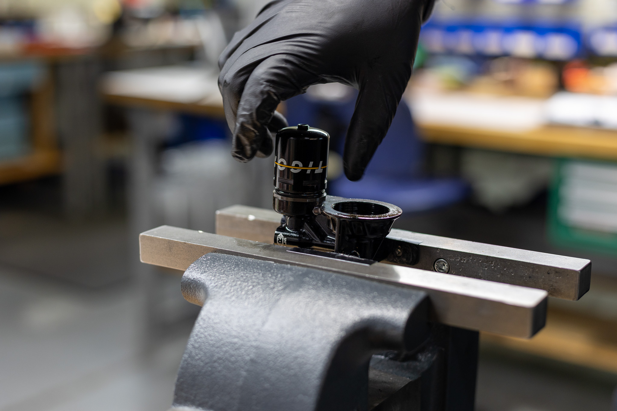
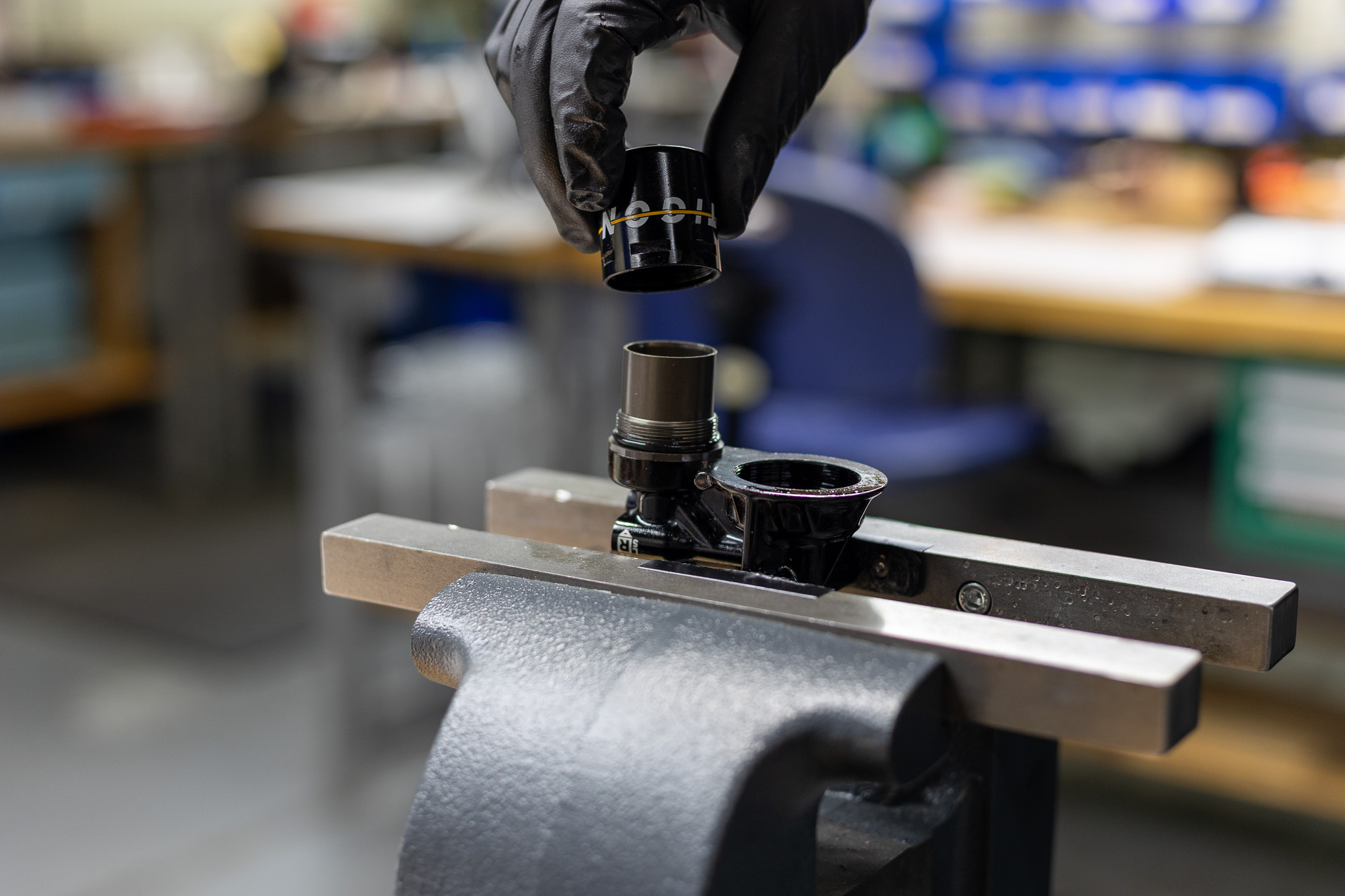
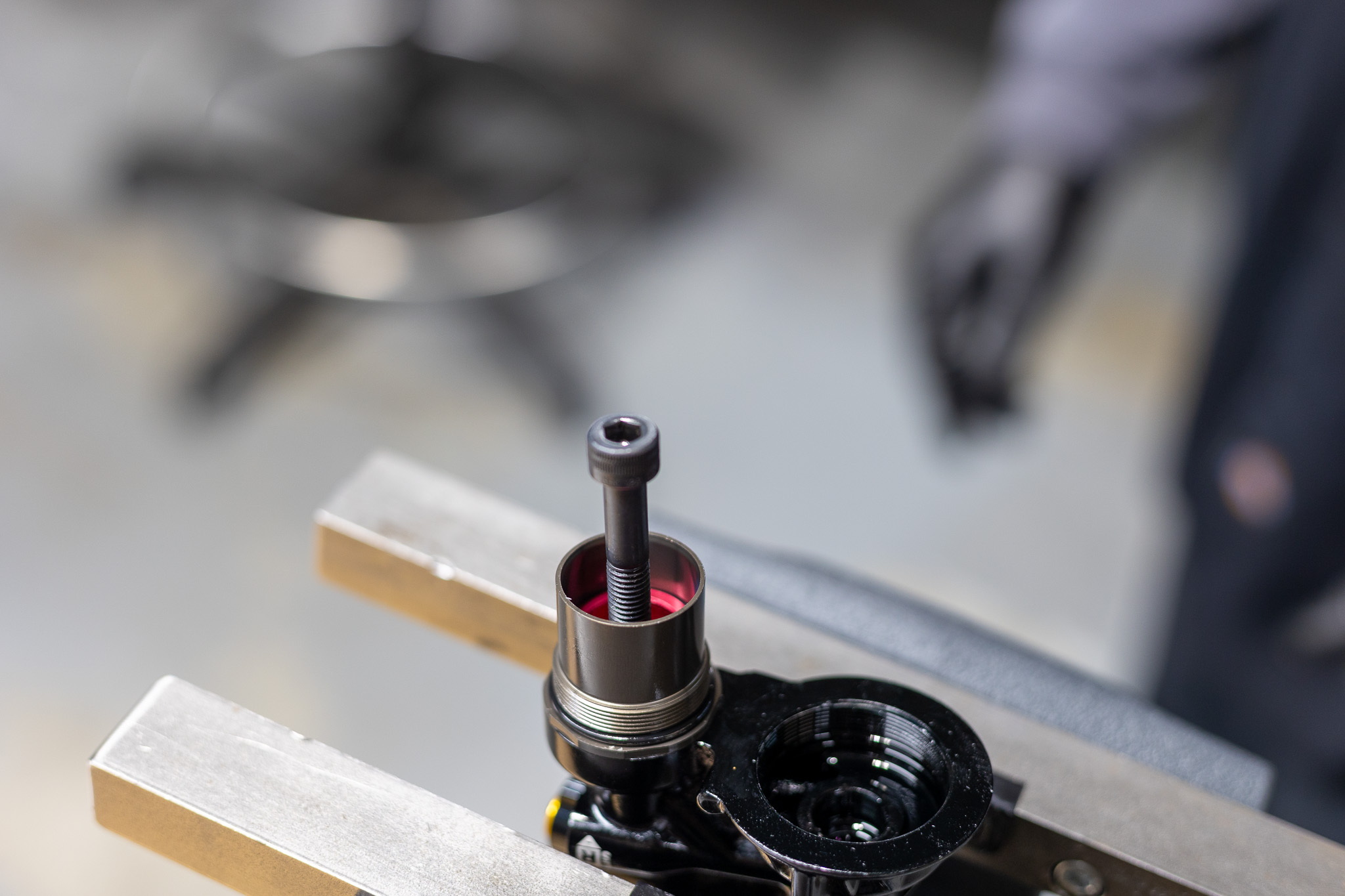
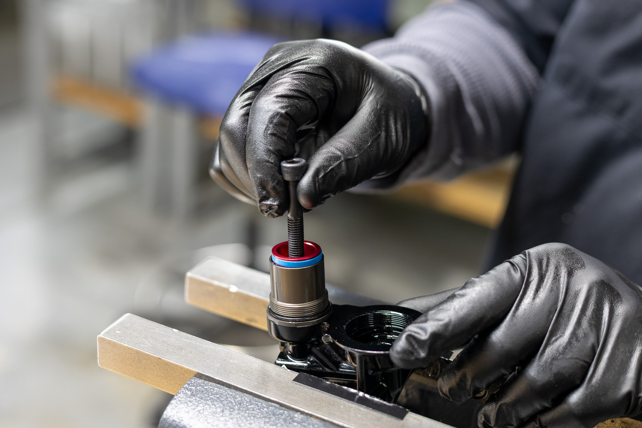
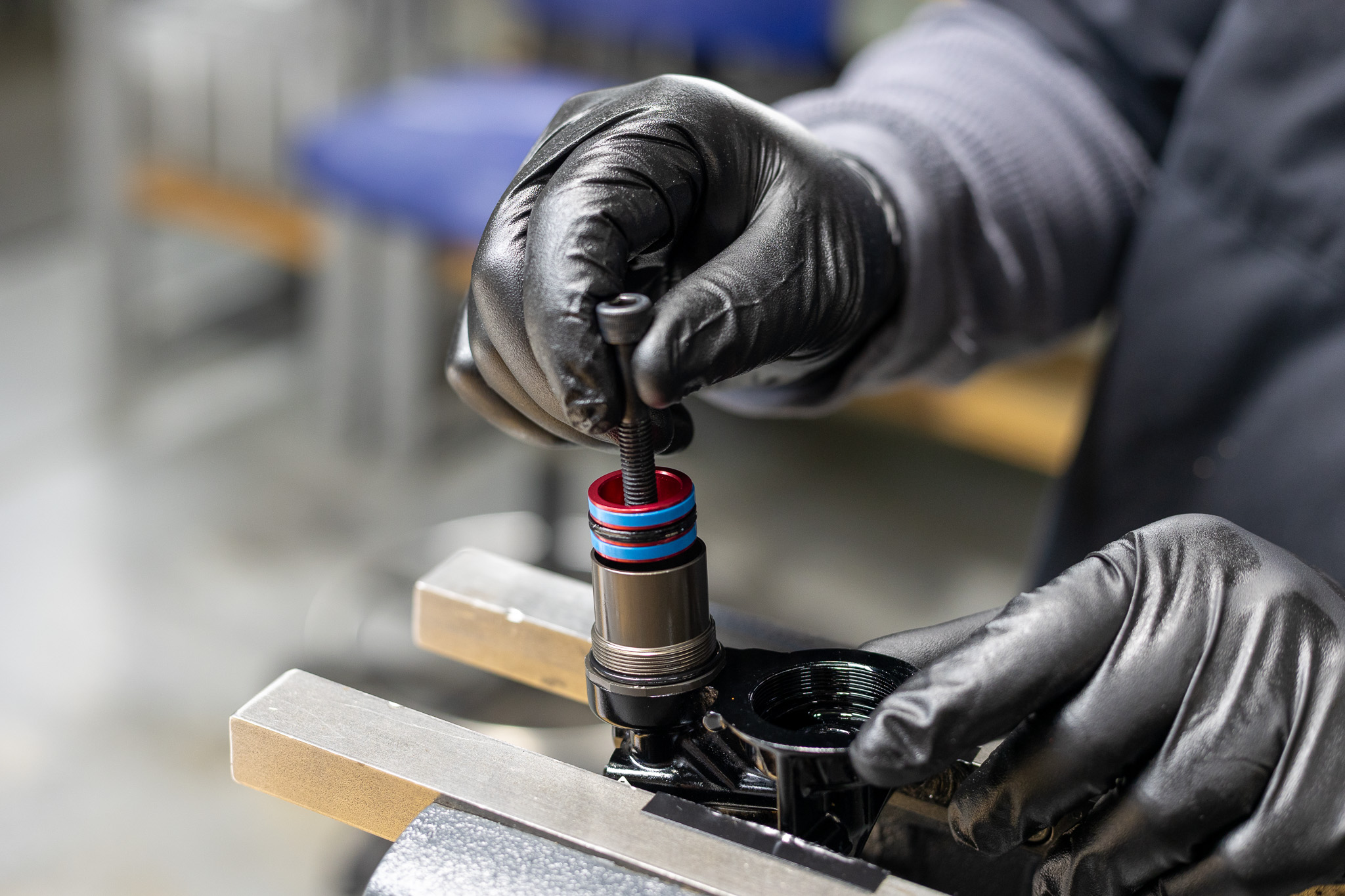
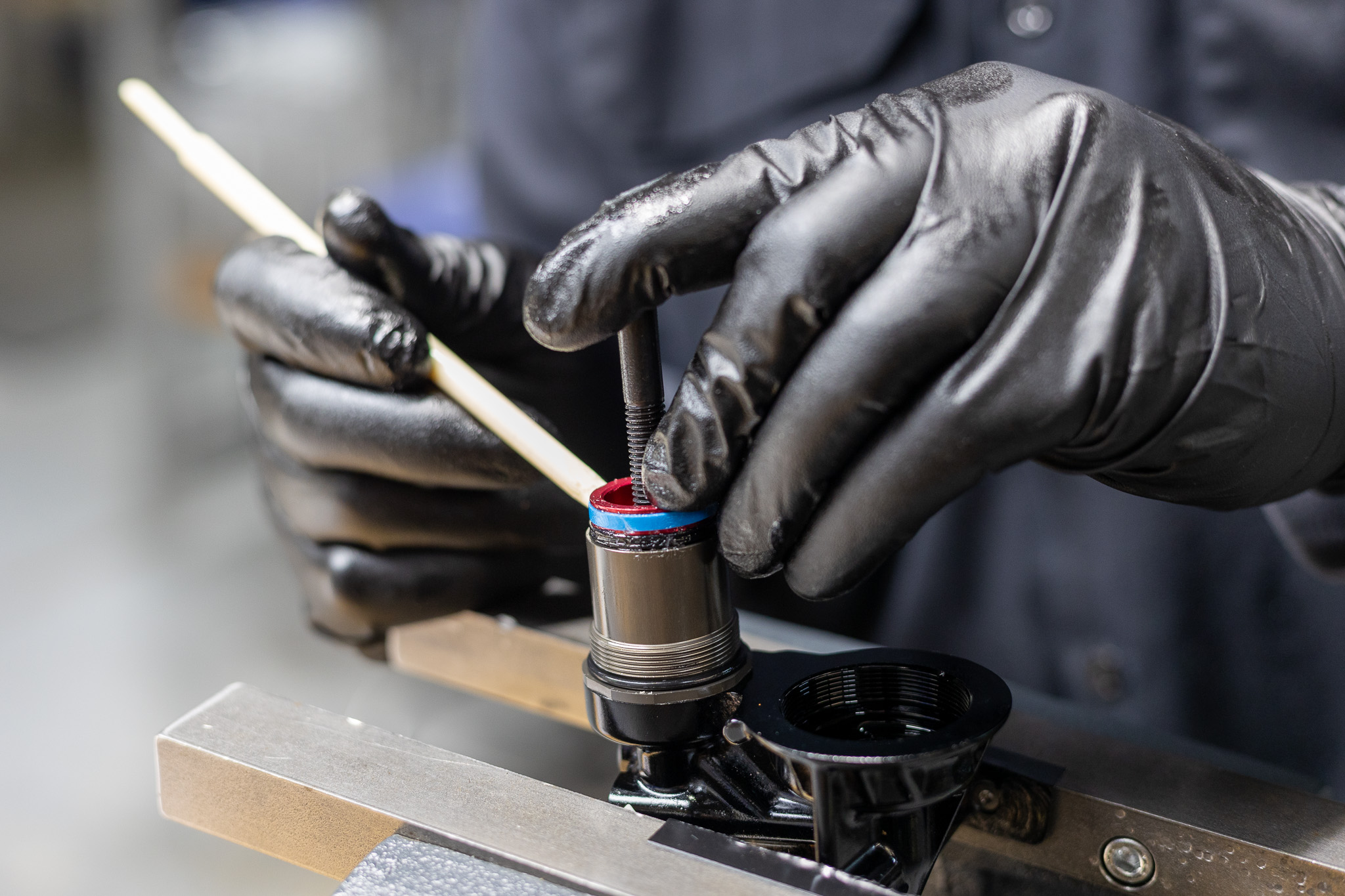
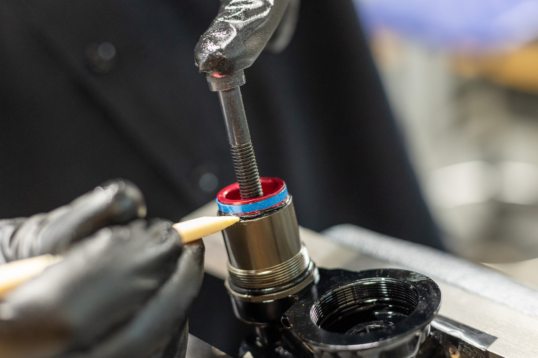
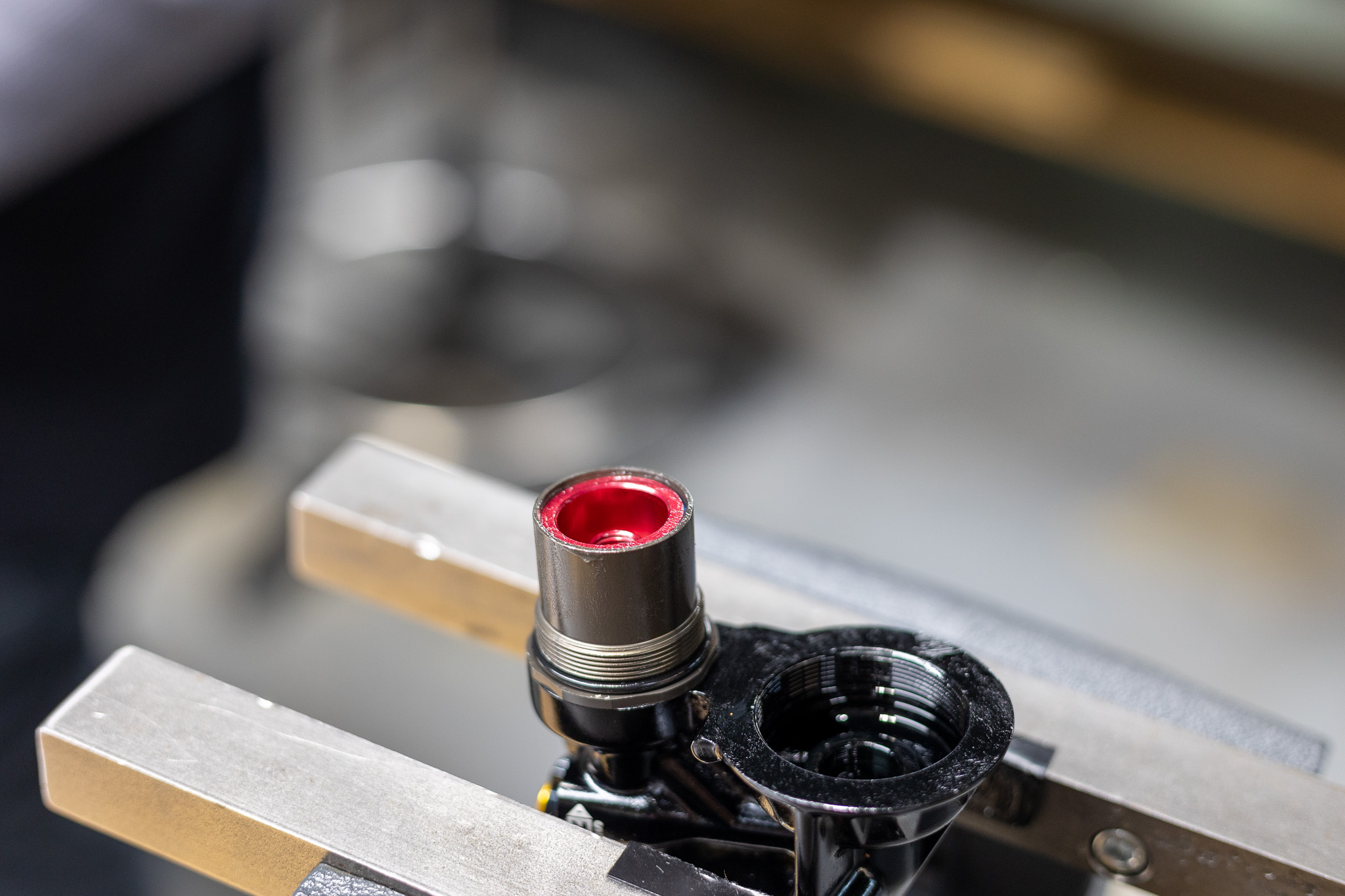
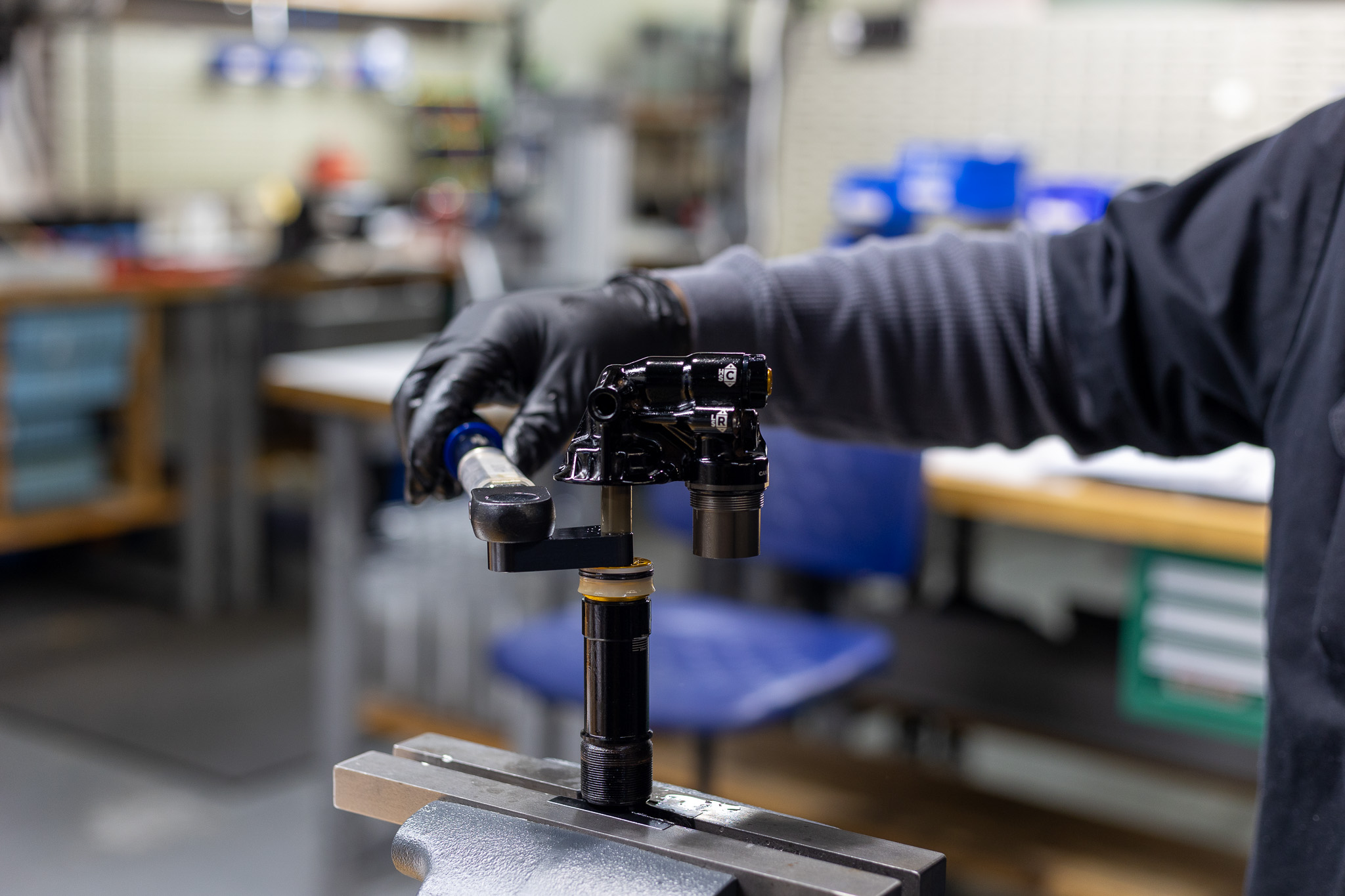
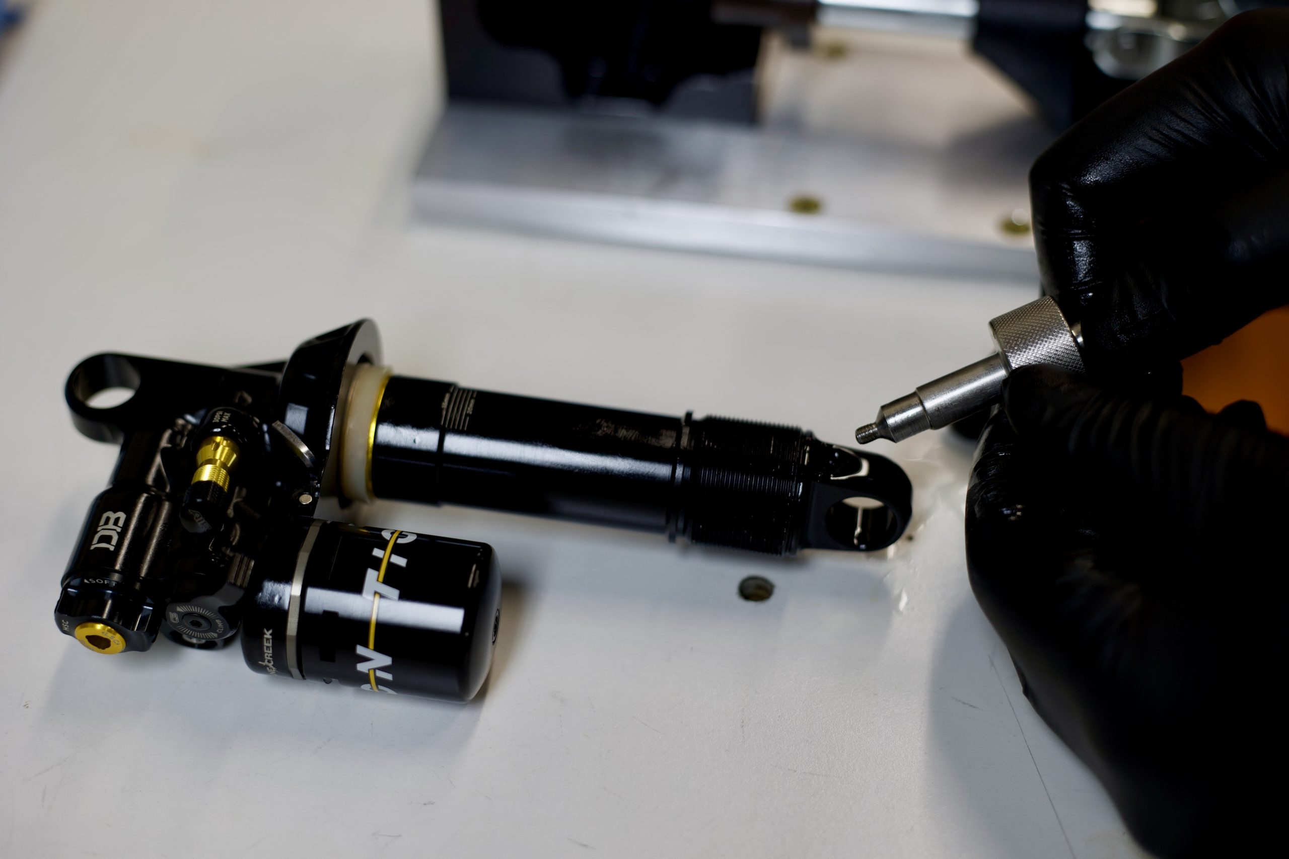
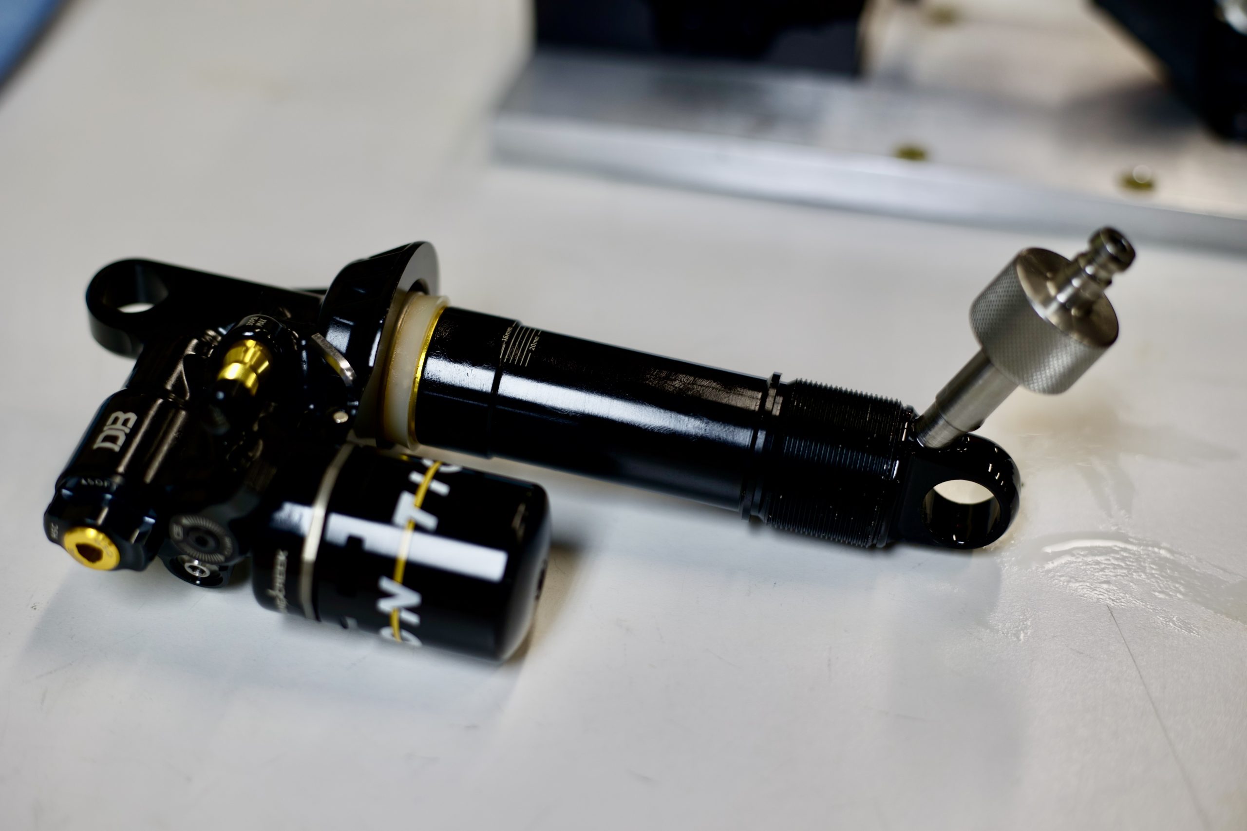
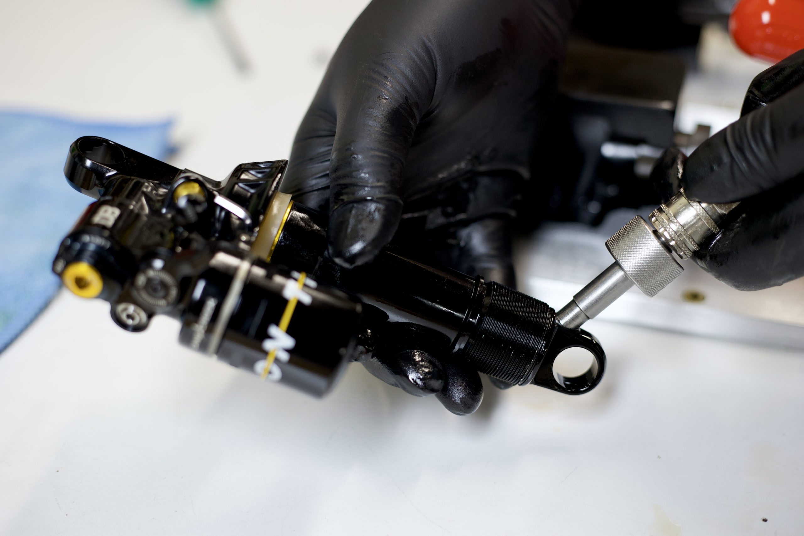
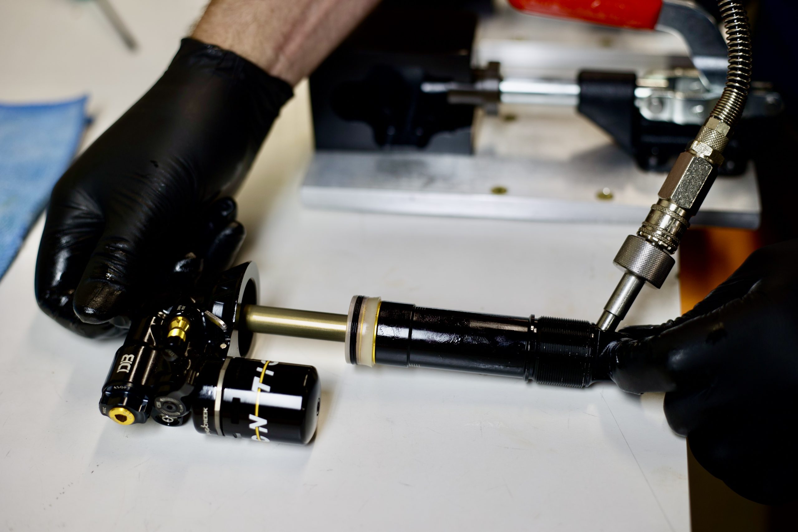
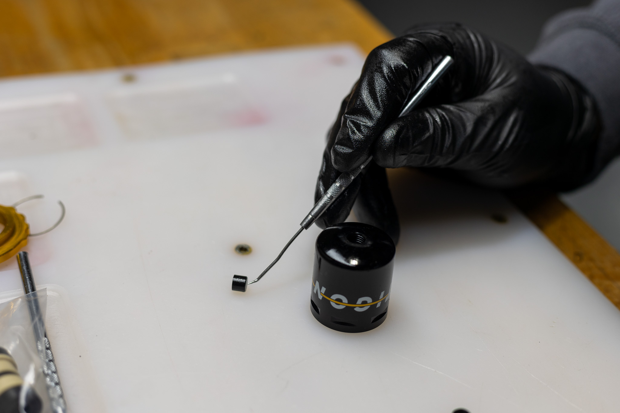
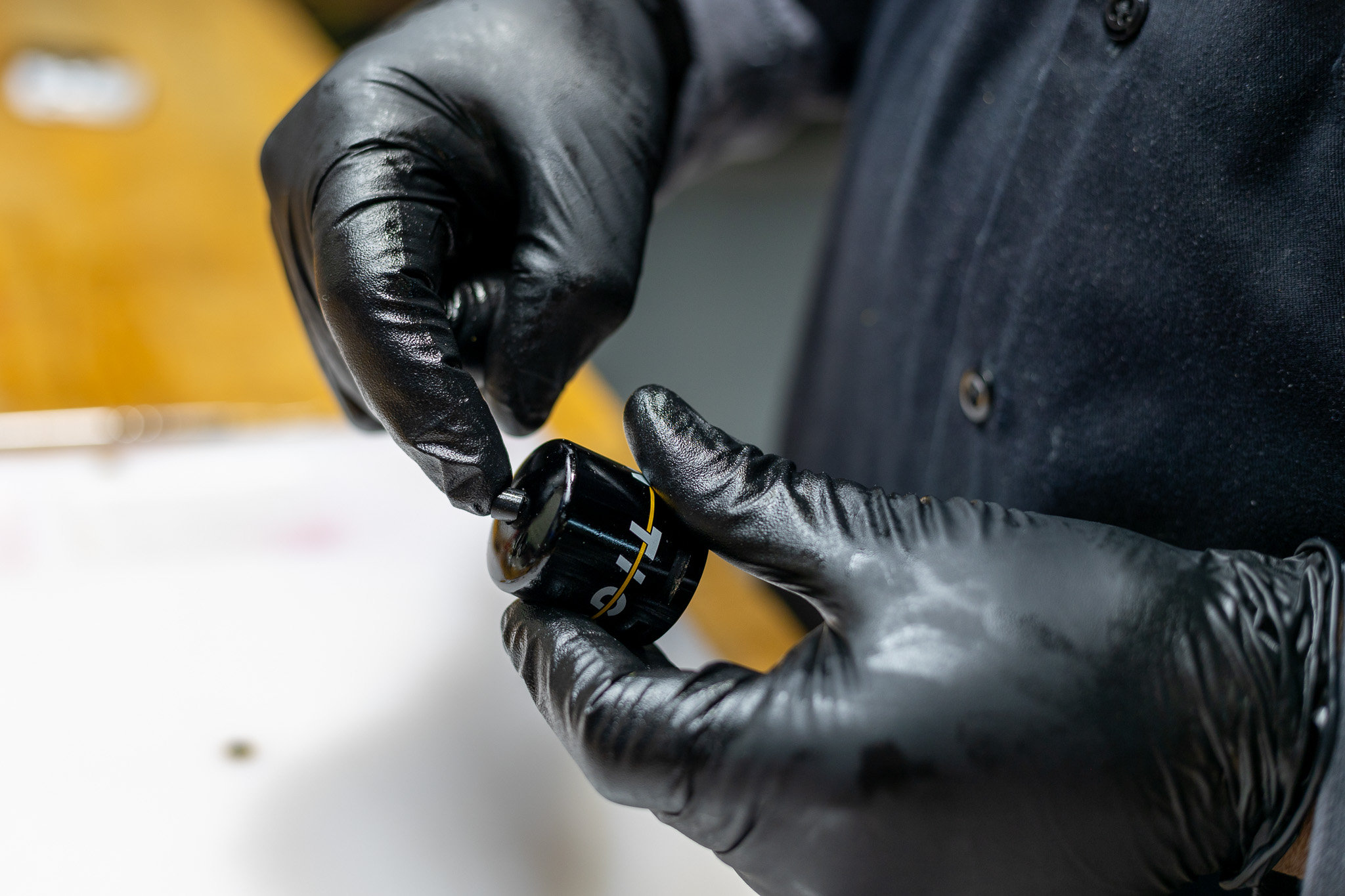
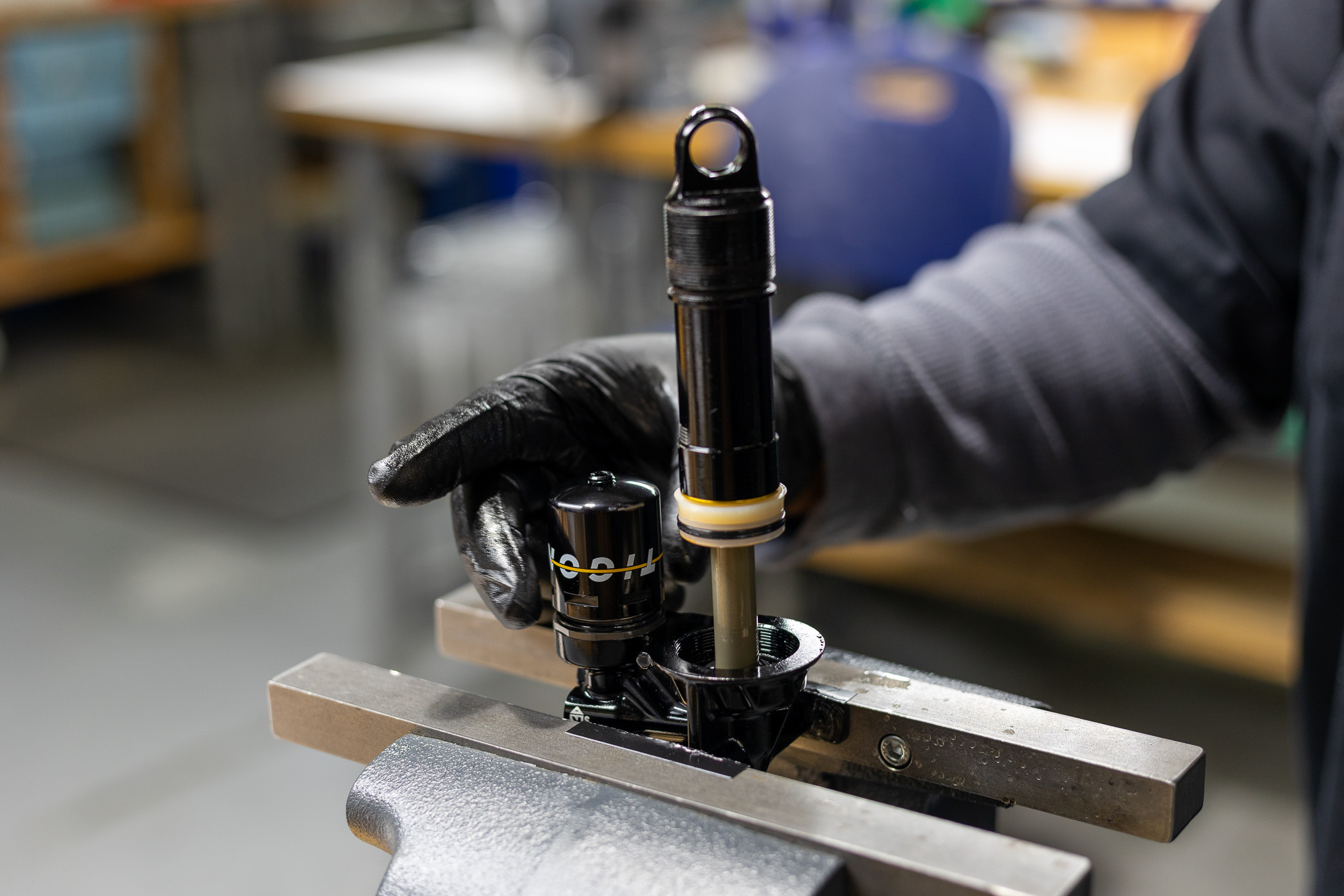
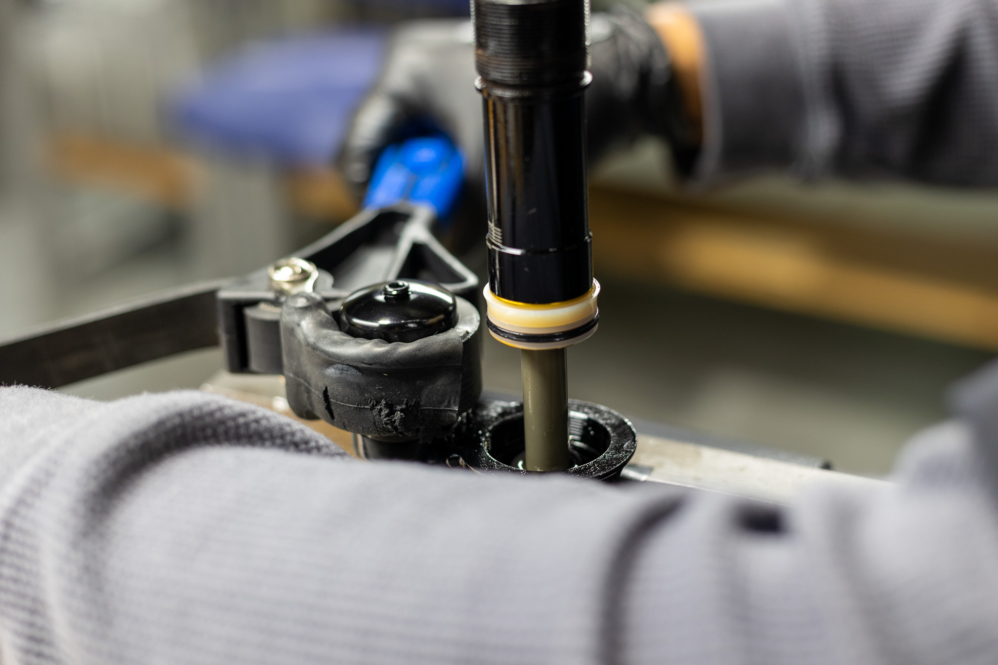
Remove fill screw using T20 wrench. Discard o-ring. Insert Tigon IFP Service Plug (ADD0328) into IFP tube, pushing the IFP to the correct depth. Install the reservoir tube onto the IFP tube to secure the IFP Plug in place. Hand tighten. Thread fill nozzle onto valve body with new fill screw o-ring (.DB11102) either on tool or in shock. Back all adjusters to fully open and open Climb Switch. Fully compress damper. Attach oil fill machine to fill port per your manufacturer’s instructions.
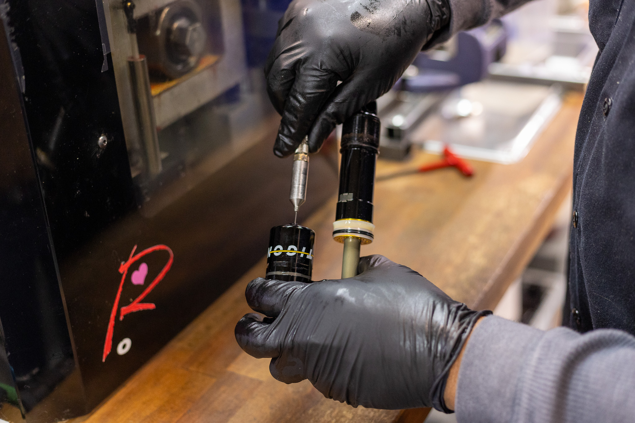
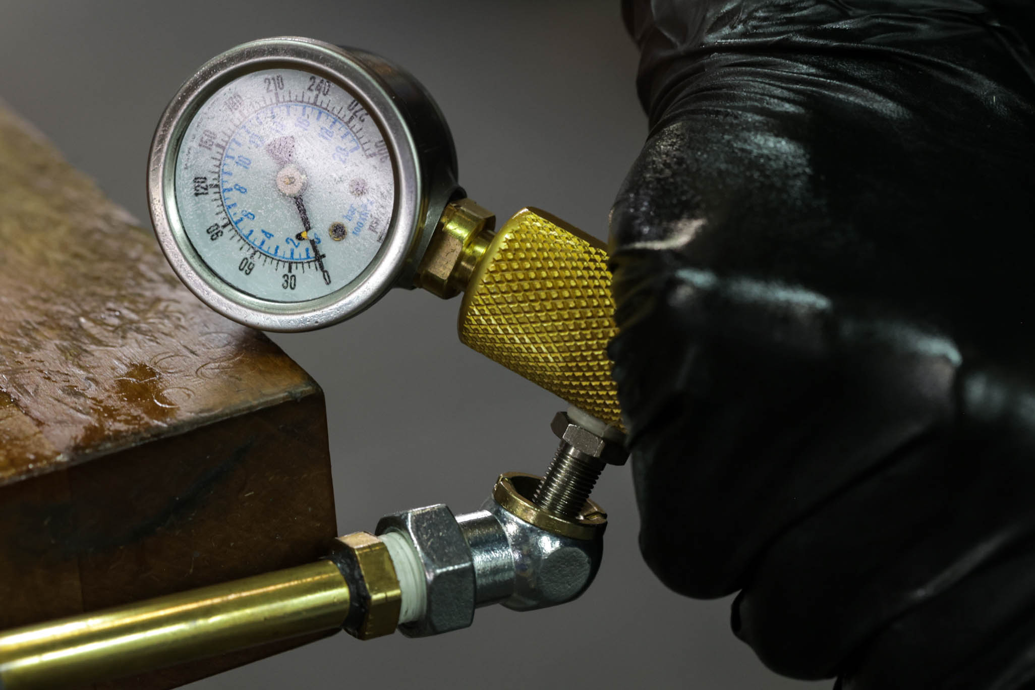
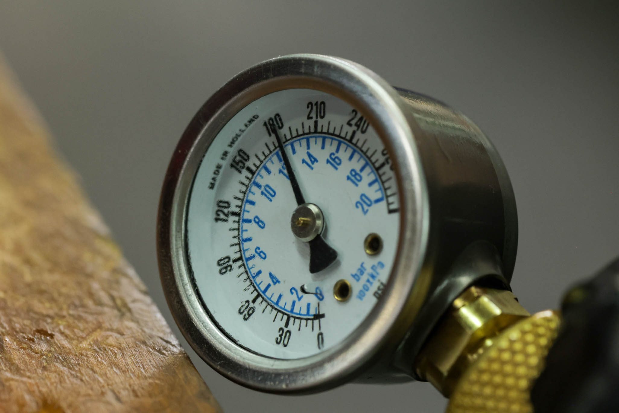
Vacuum system to (4) mbar. Pressure with Oil to (3) bar. Slowly cycle shaft finishing with shaft fully out. Cut fill and equalize pressure. Vacuum system to (4) mbar, leaving shaft out. Pressure again with Oil to (3) bar. Slowly cycle shaft finishing with shaft fully out. Cut fill.
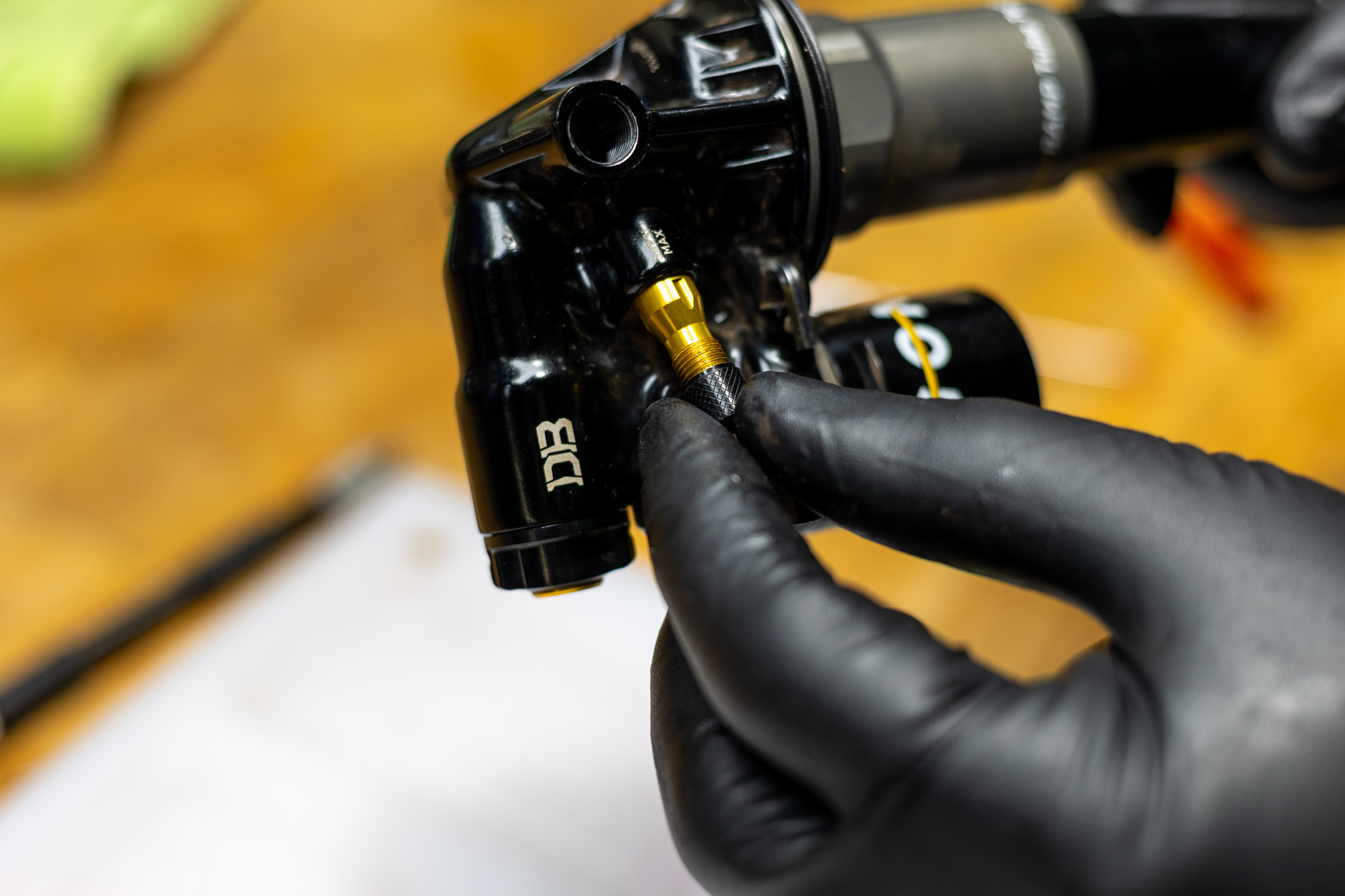
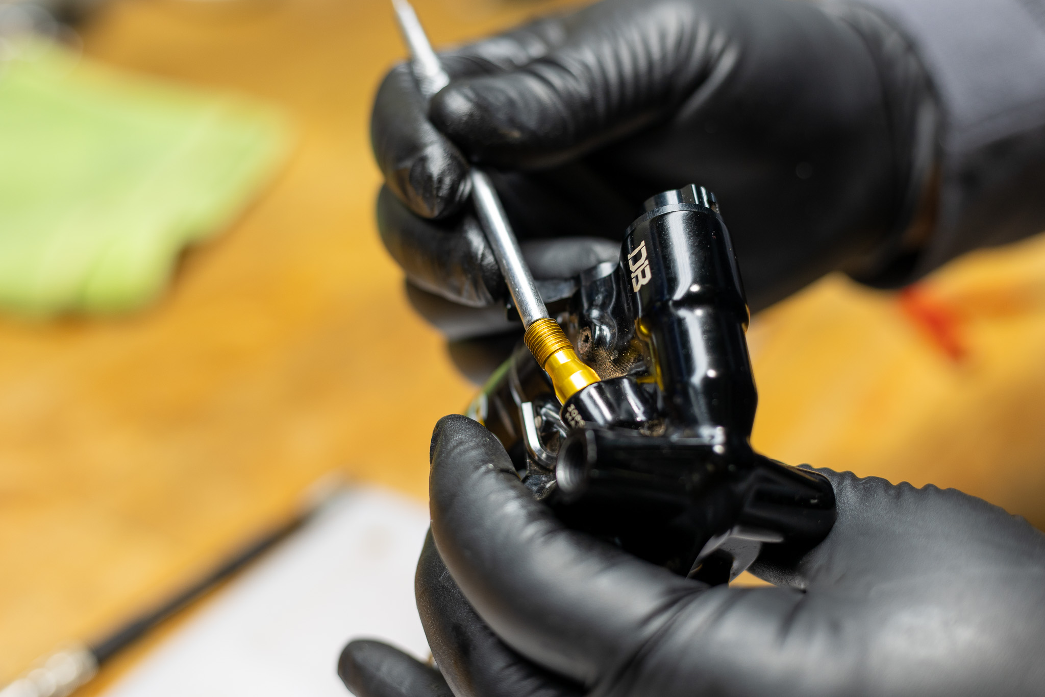
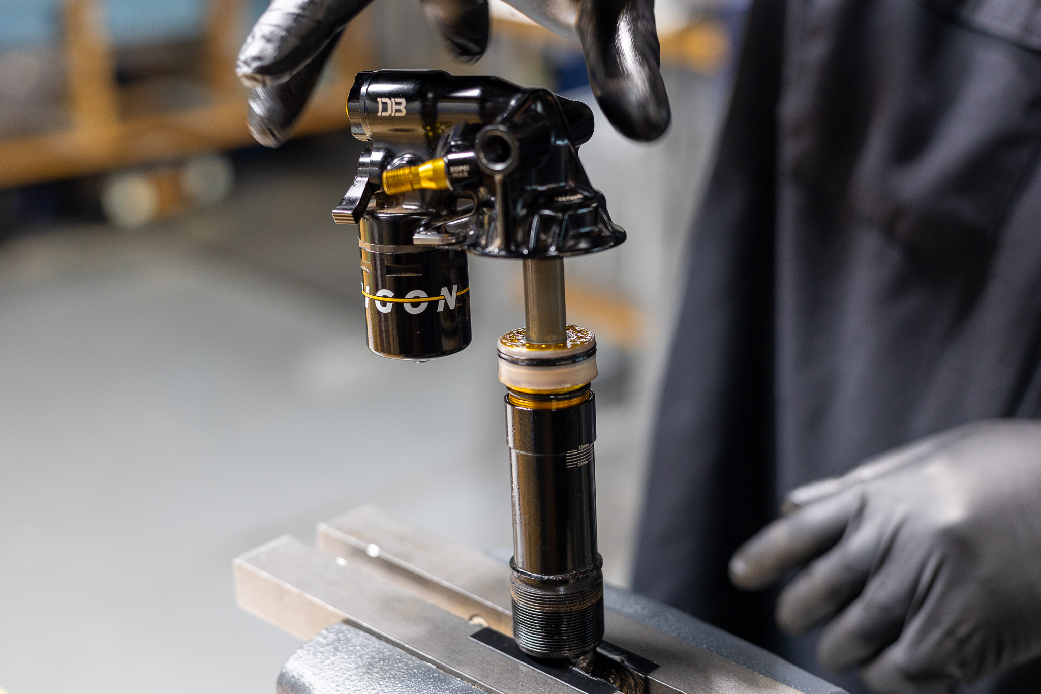
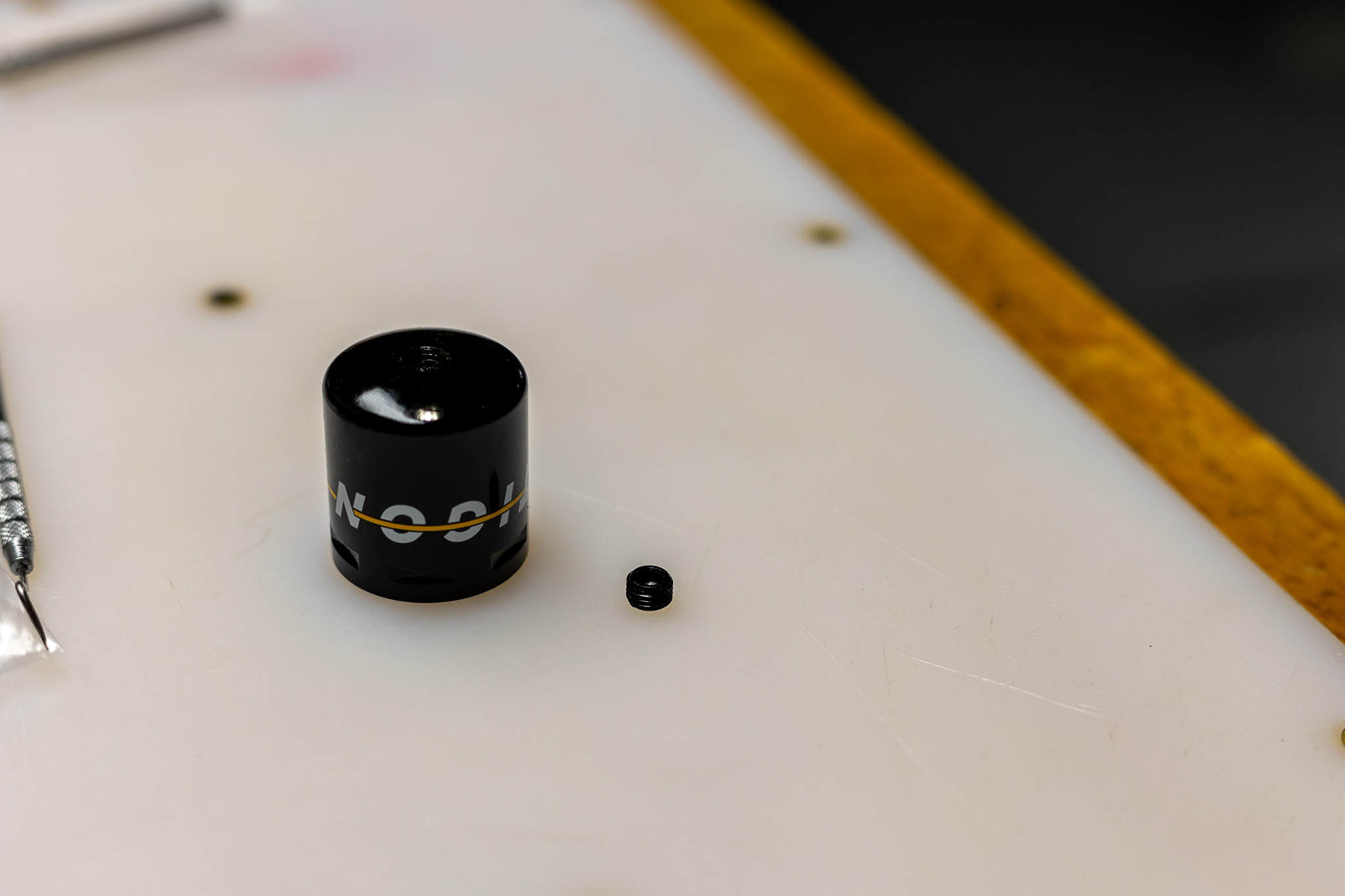
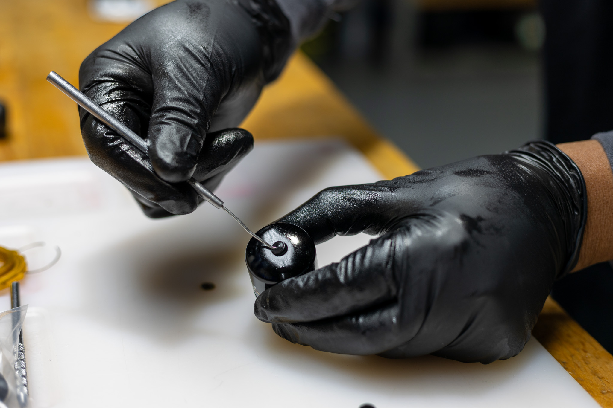
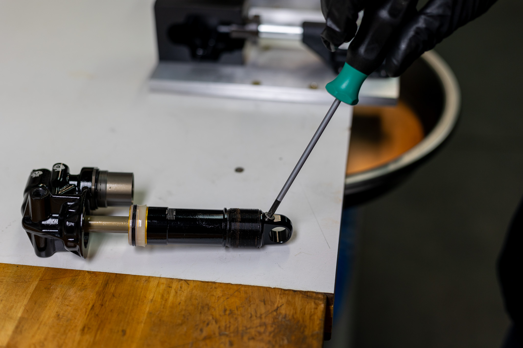
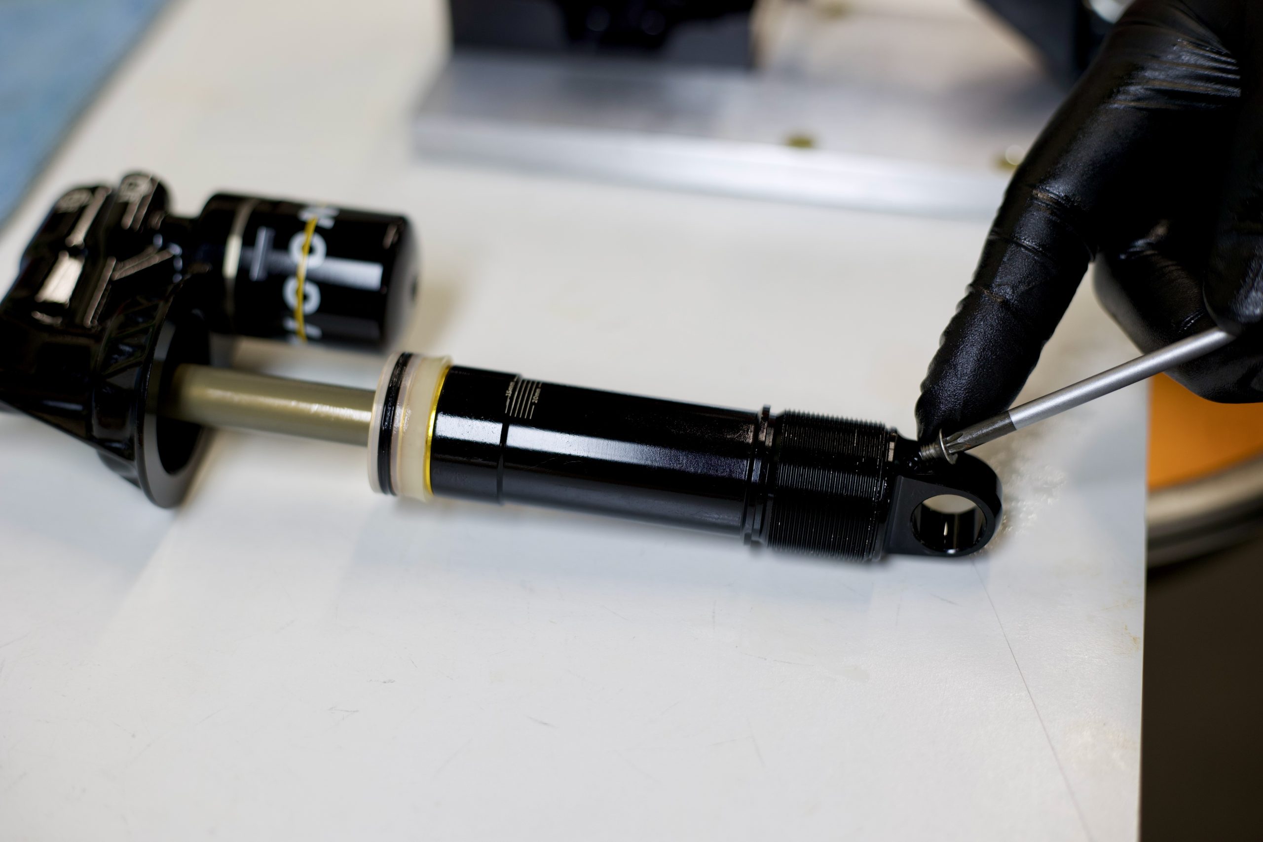
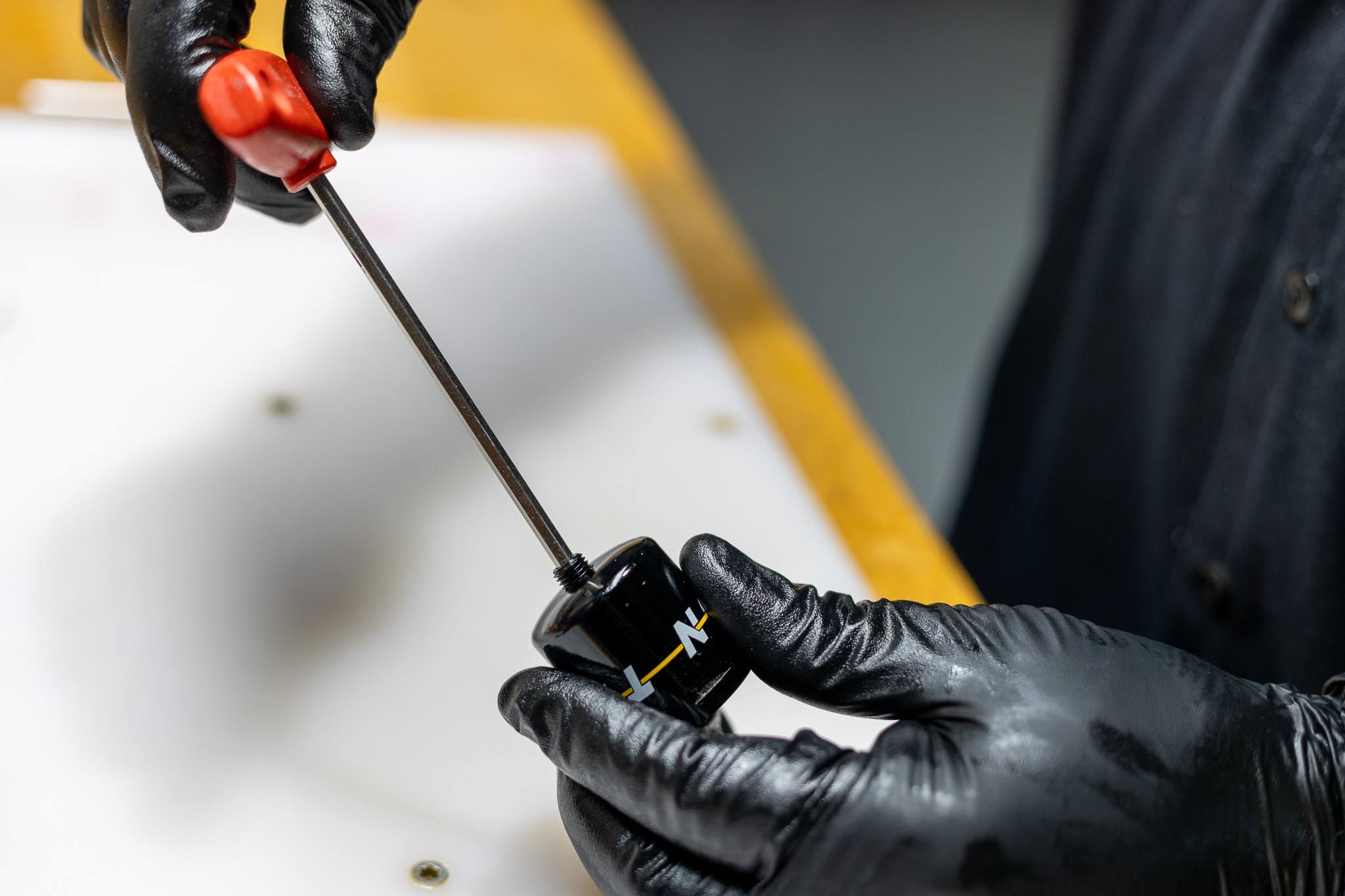
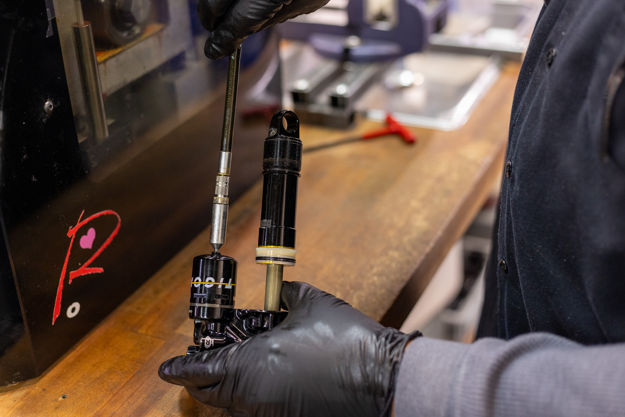
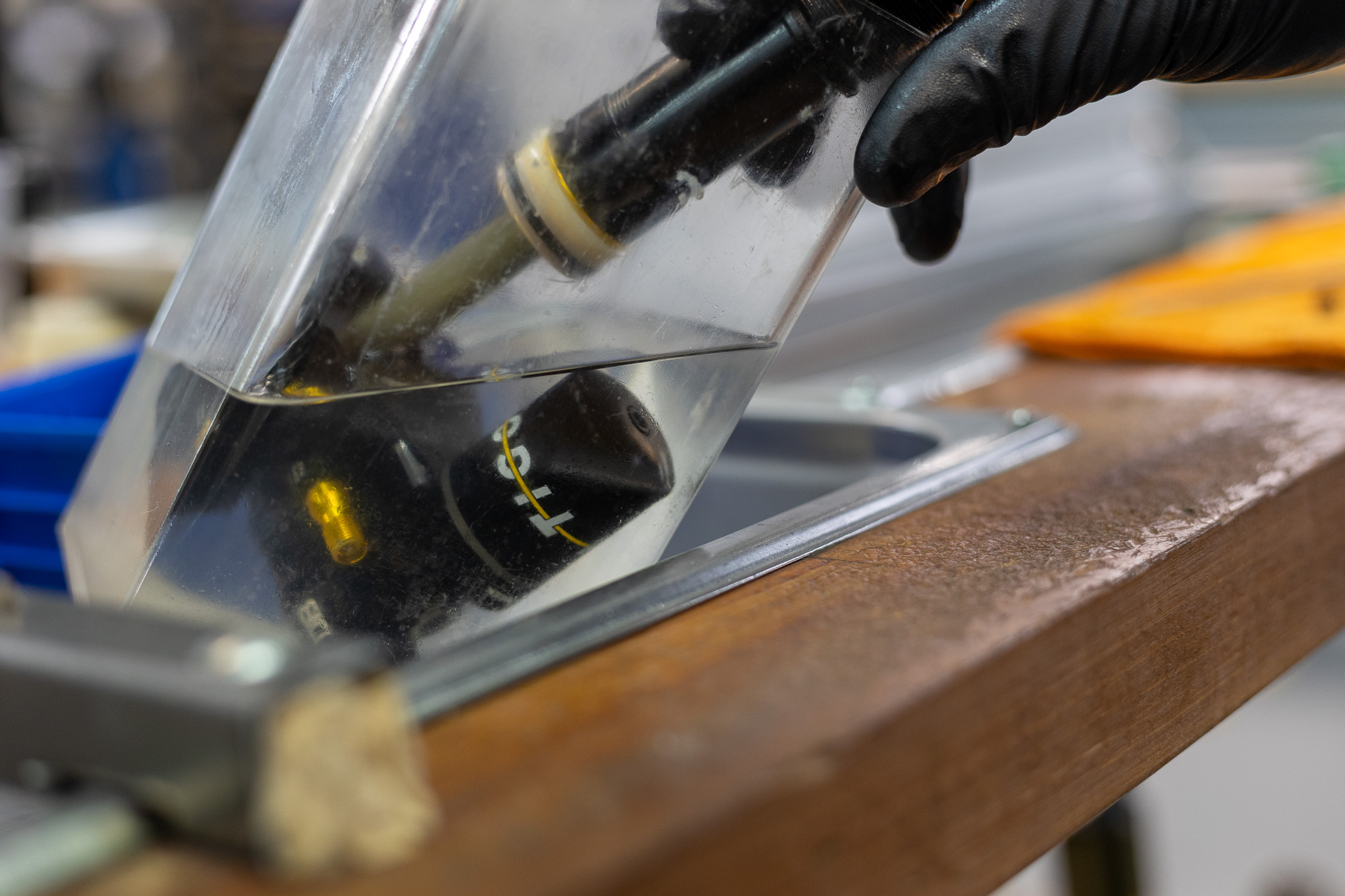
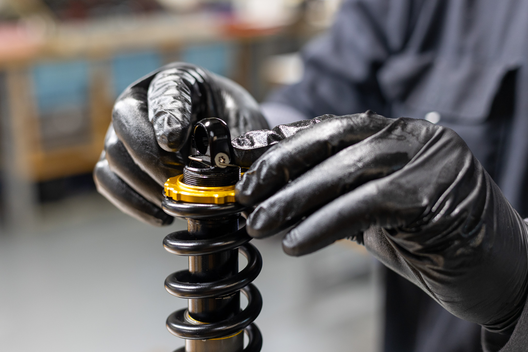
Insert gas fill needle in gas fill port on reservoir tube. Pressurize to 11-12 bars of nitrogen. Tighten fill plug set screw with 4mm. Compress shaft and ensure proper gas by observing shaft return to full extension. Submerge valve body in water to check for gas leaks.
If mechanical dyno equipment is available, run shock on dyno at this point.
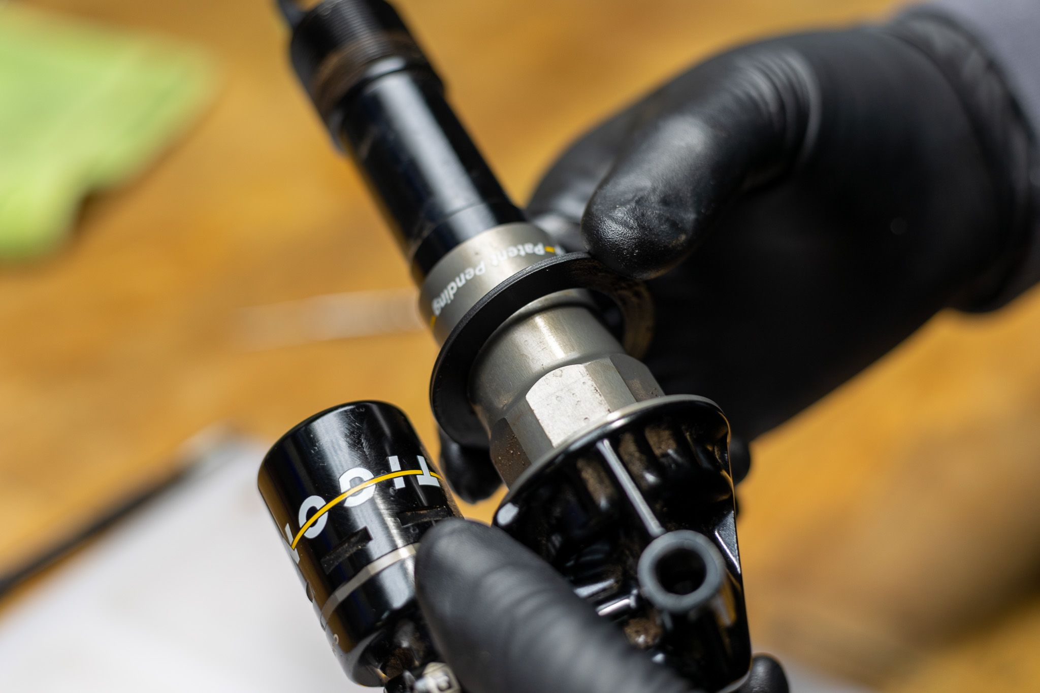
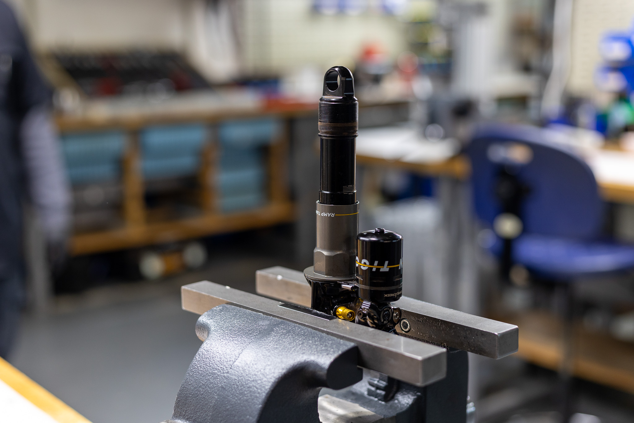
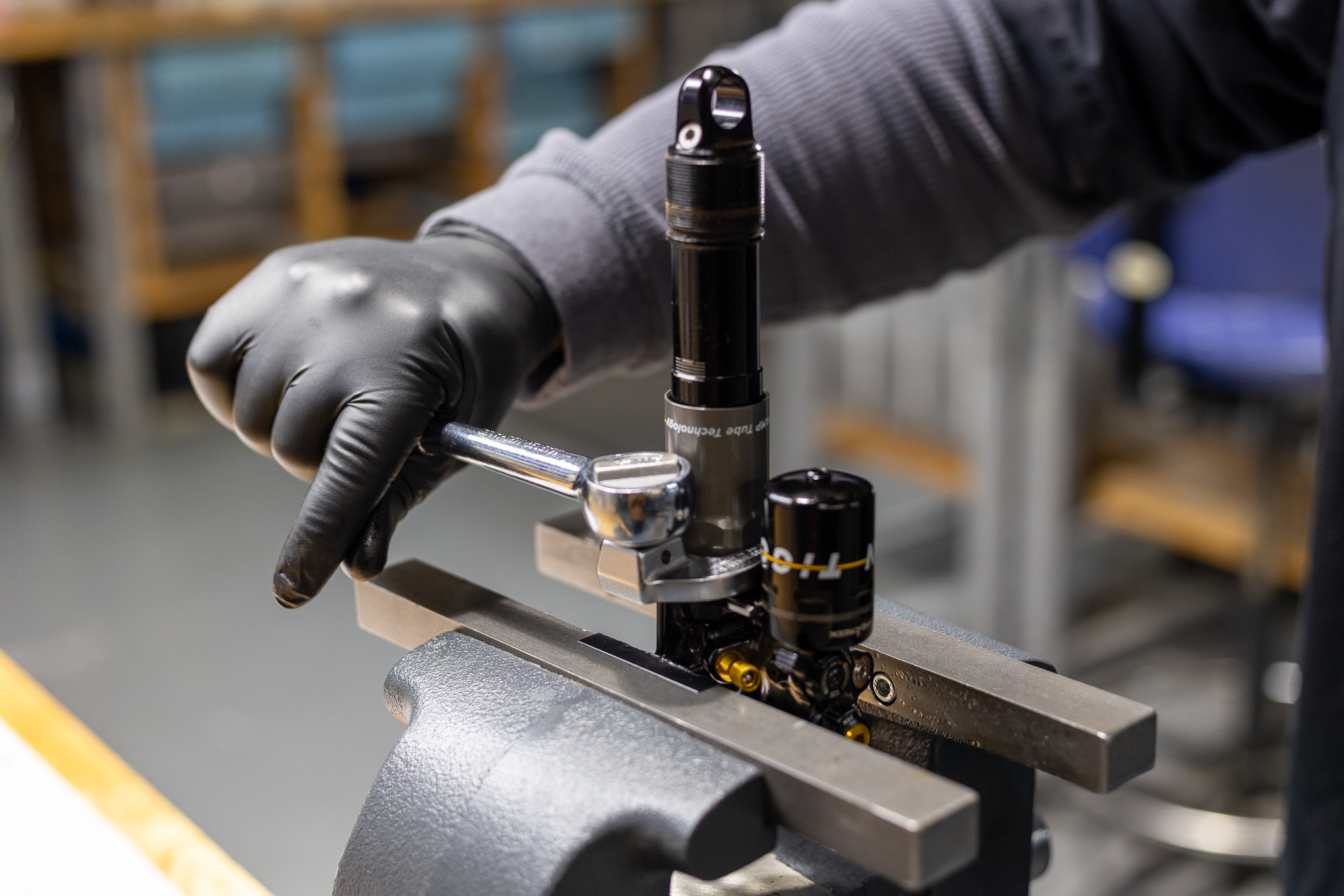
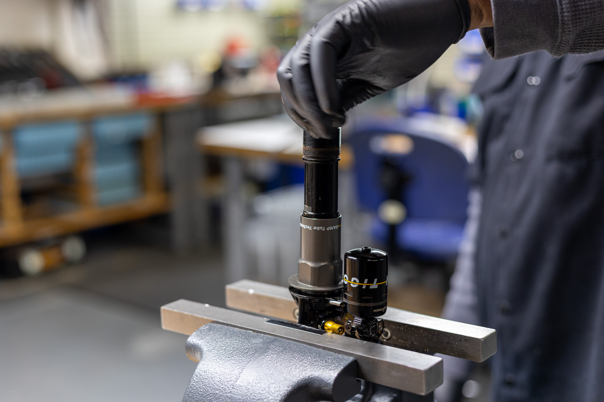
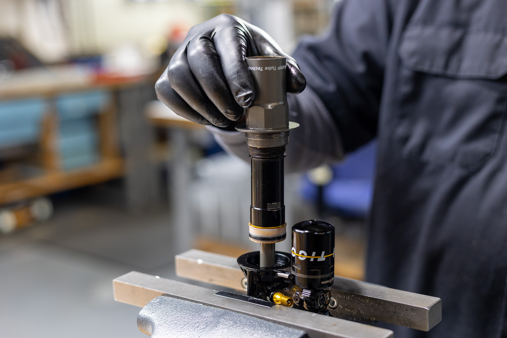
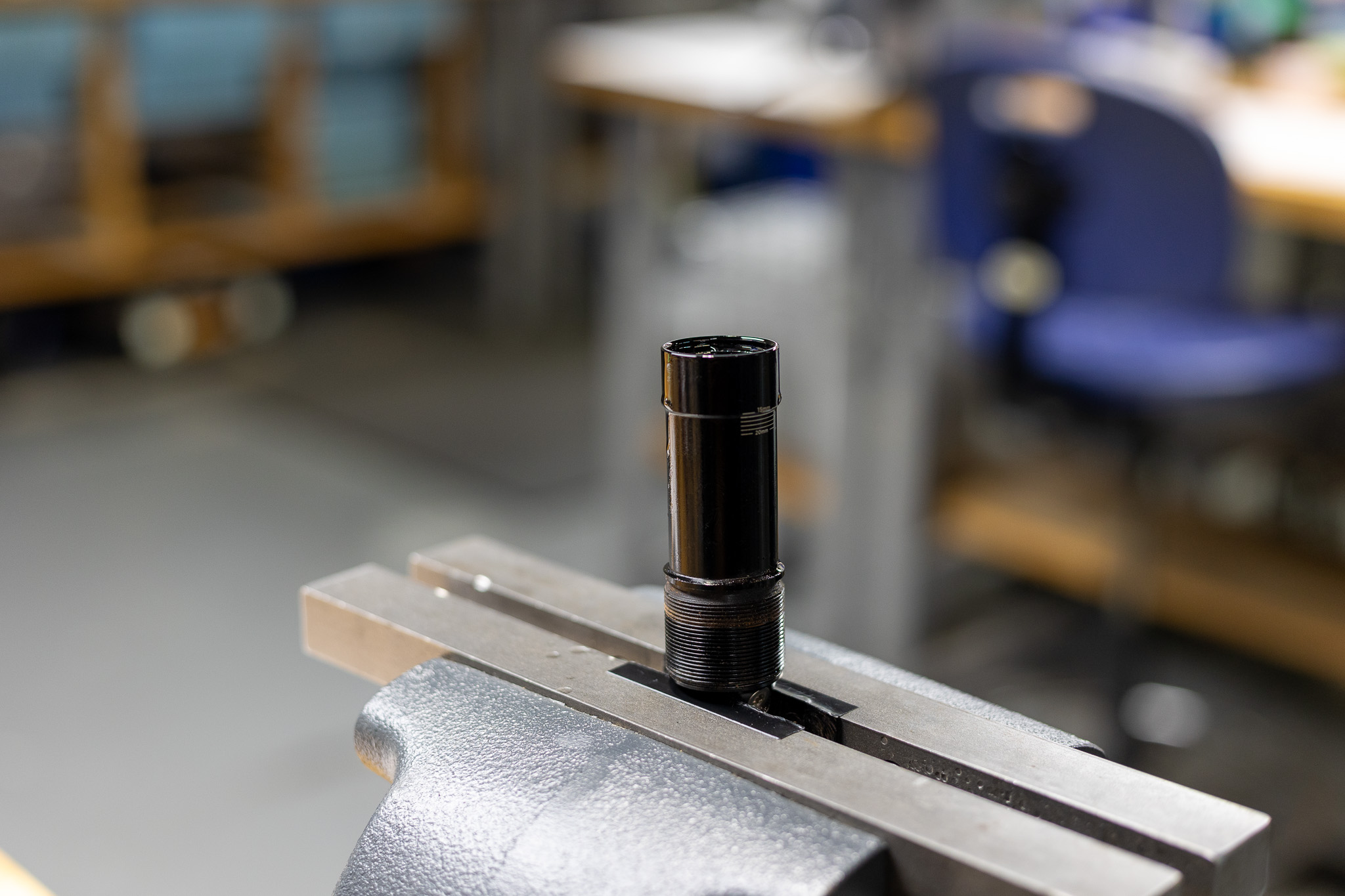
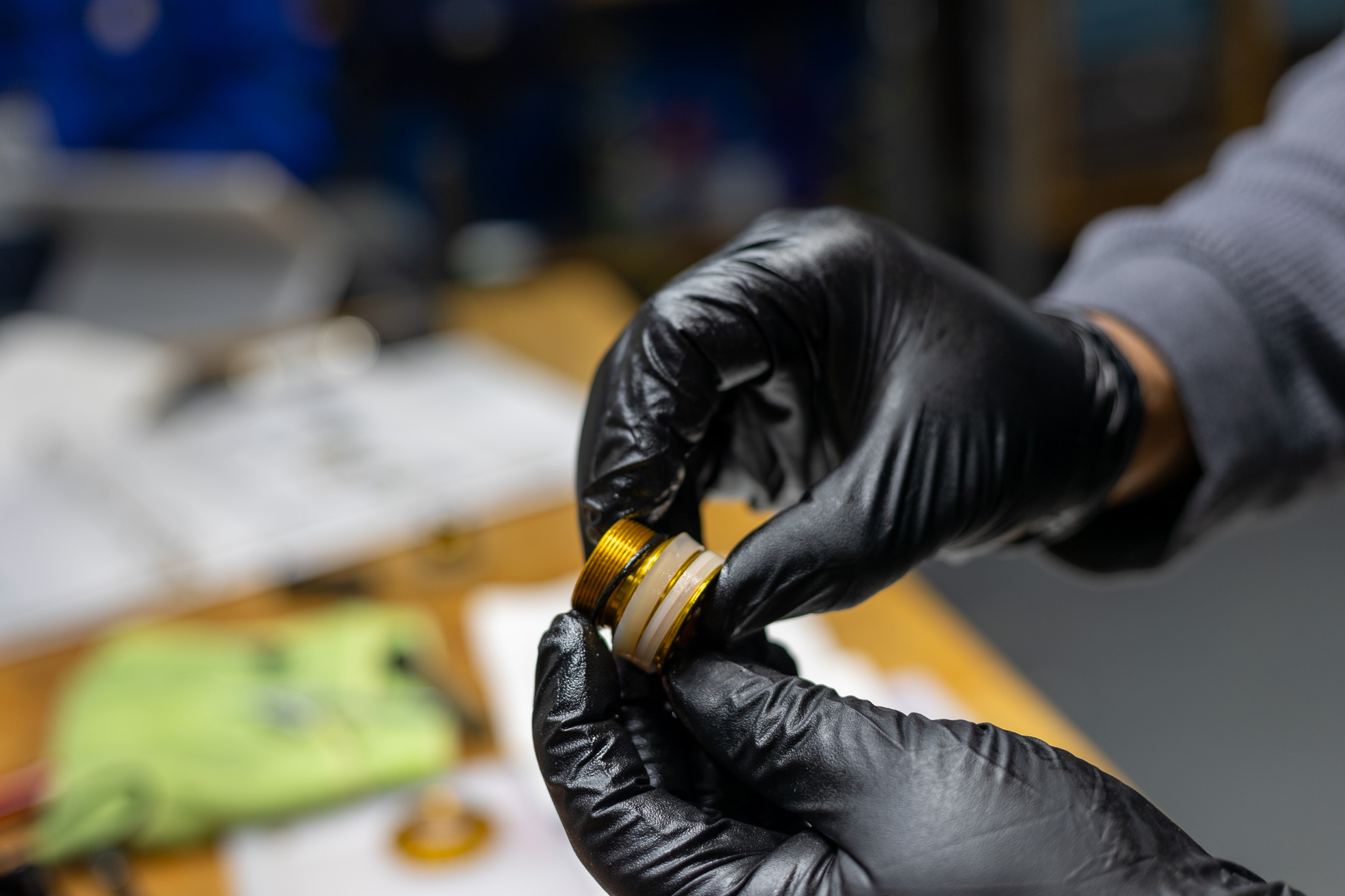
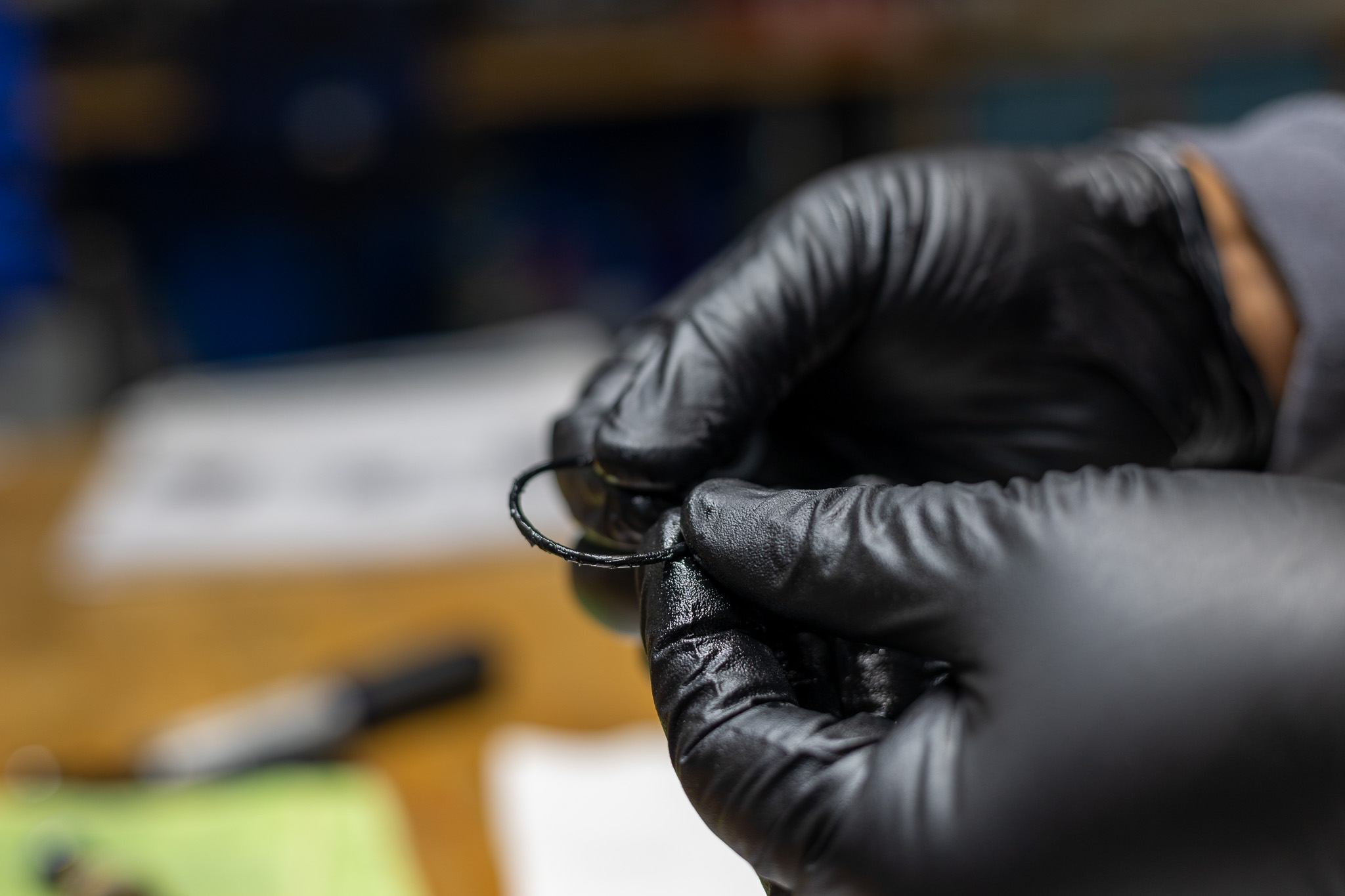
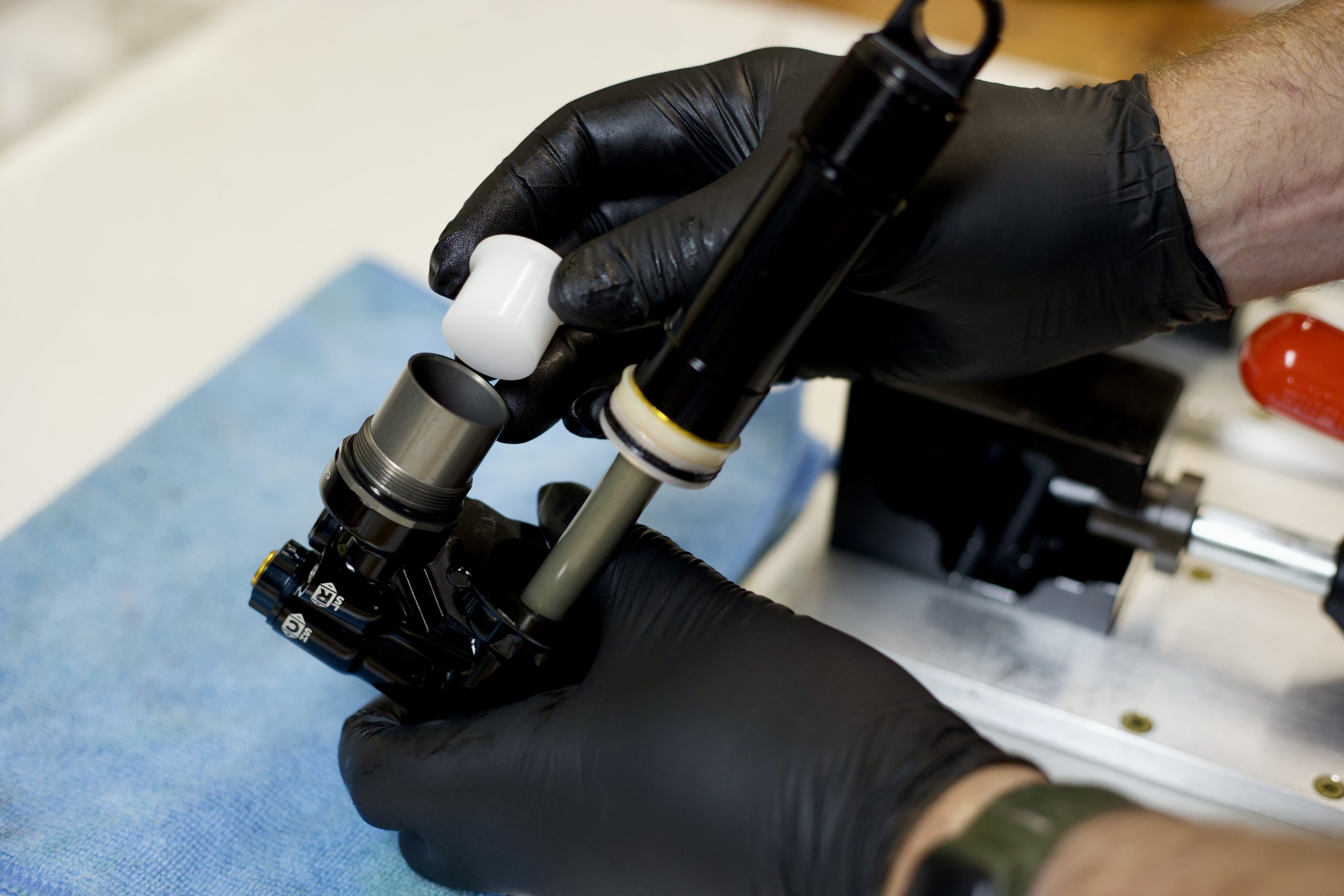
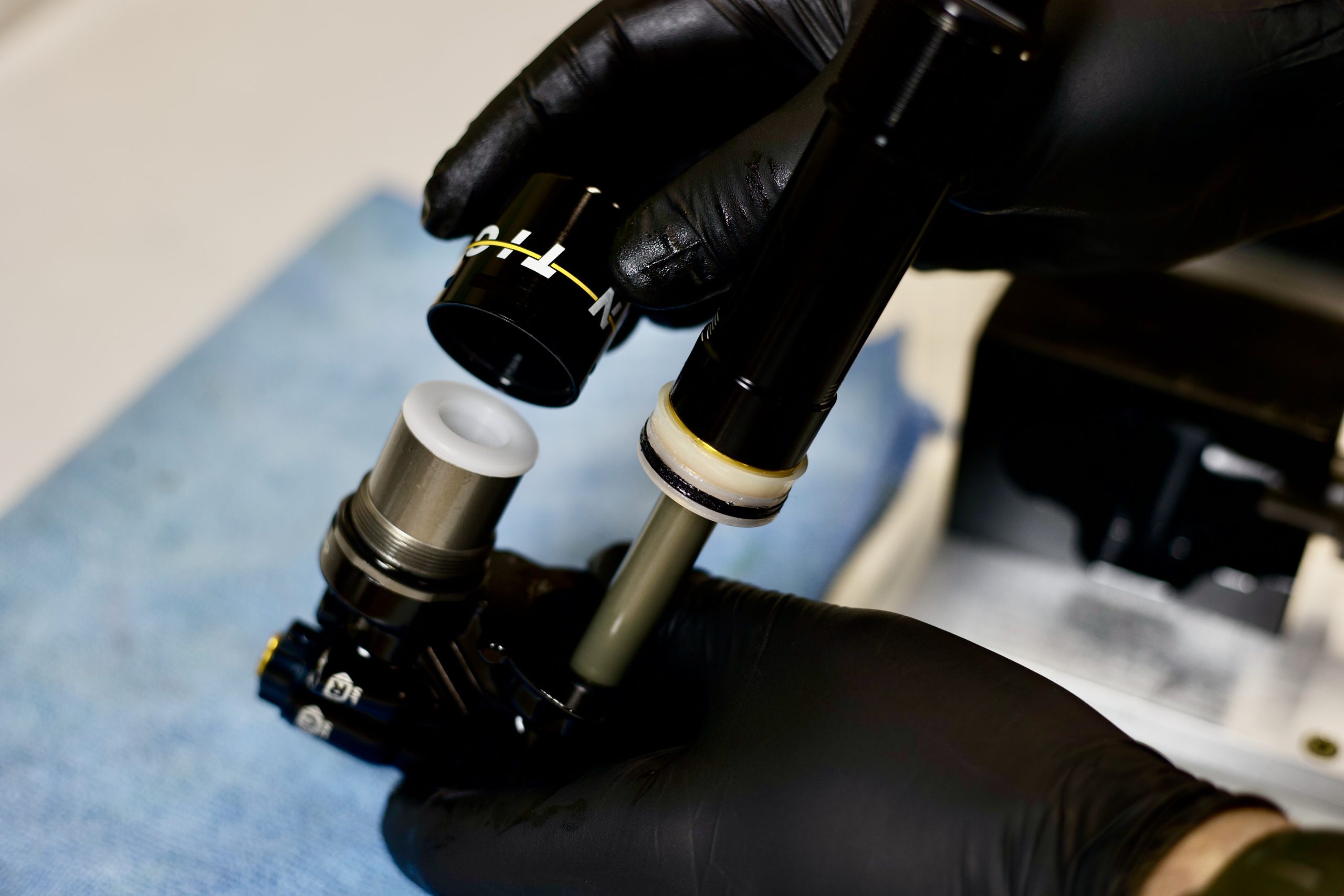
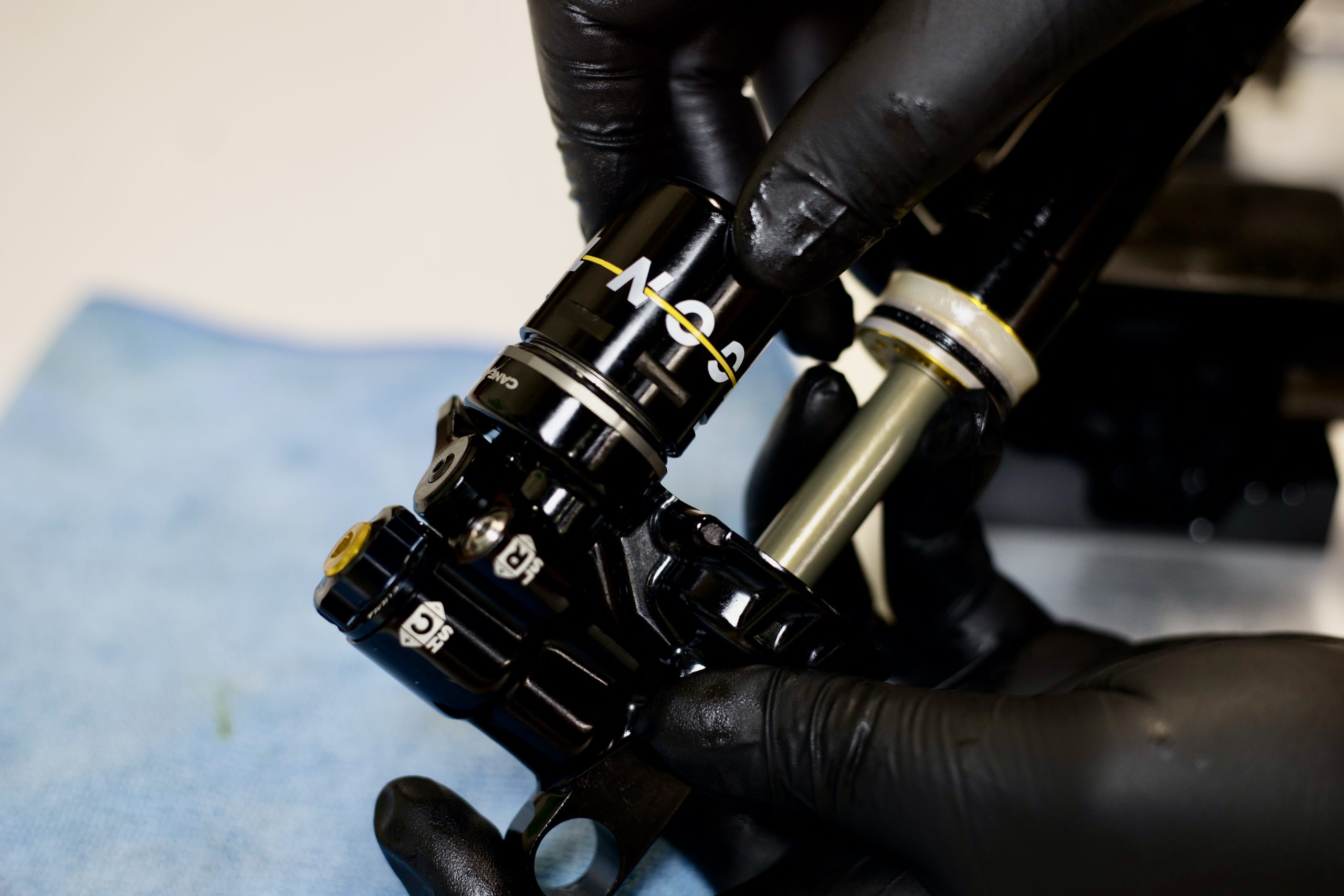
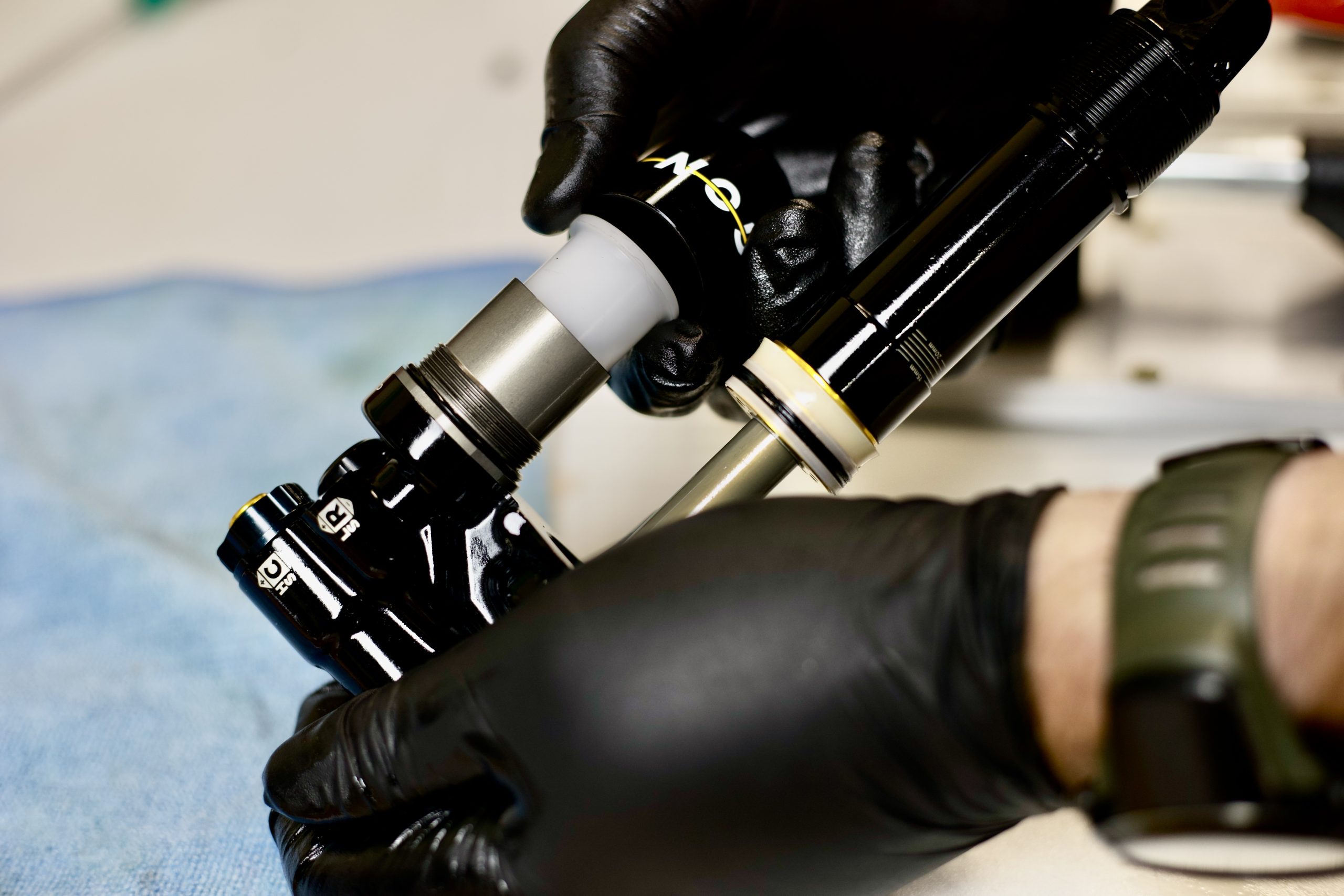
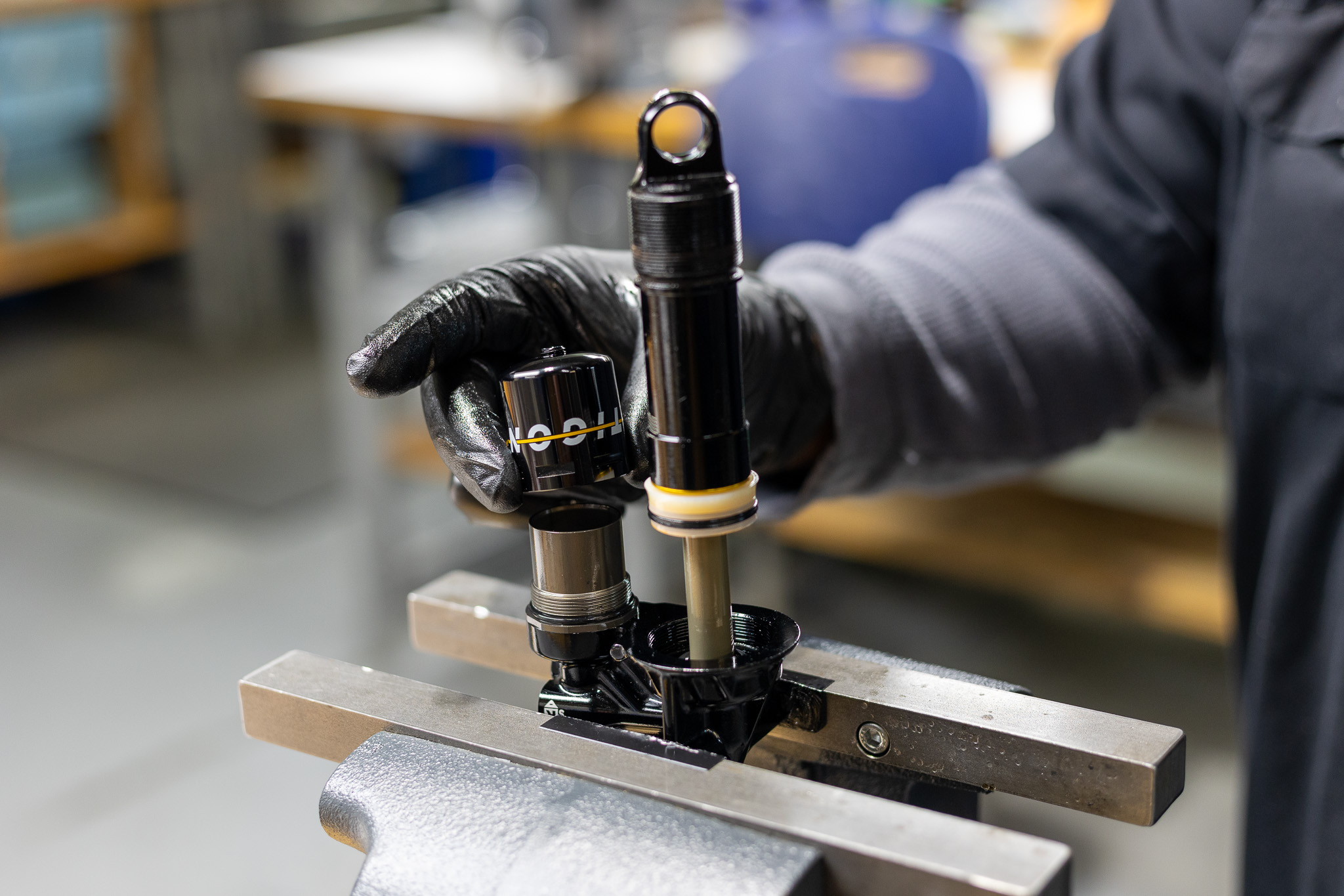
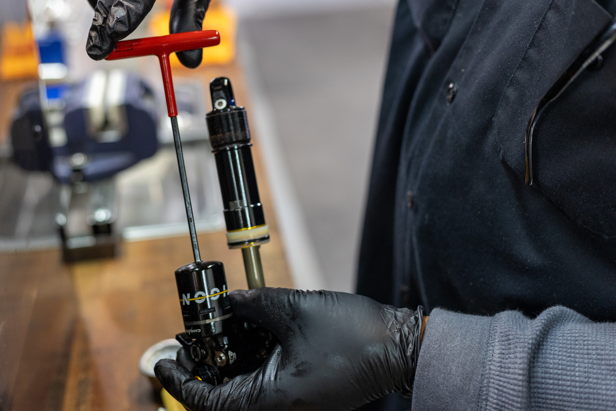
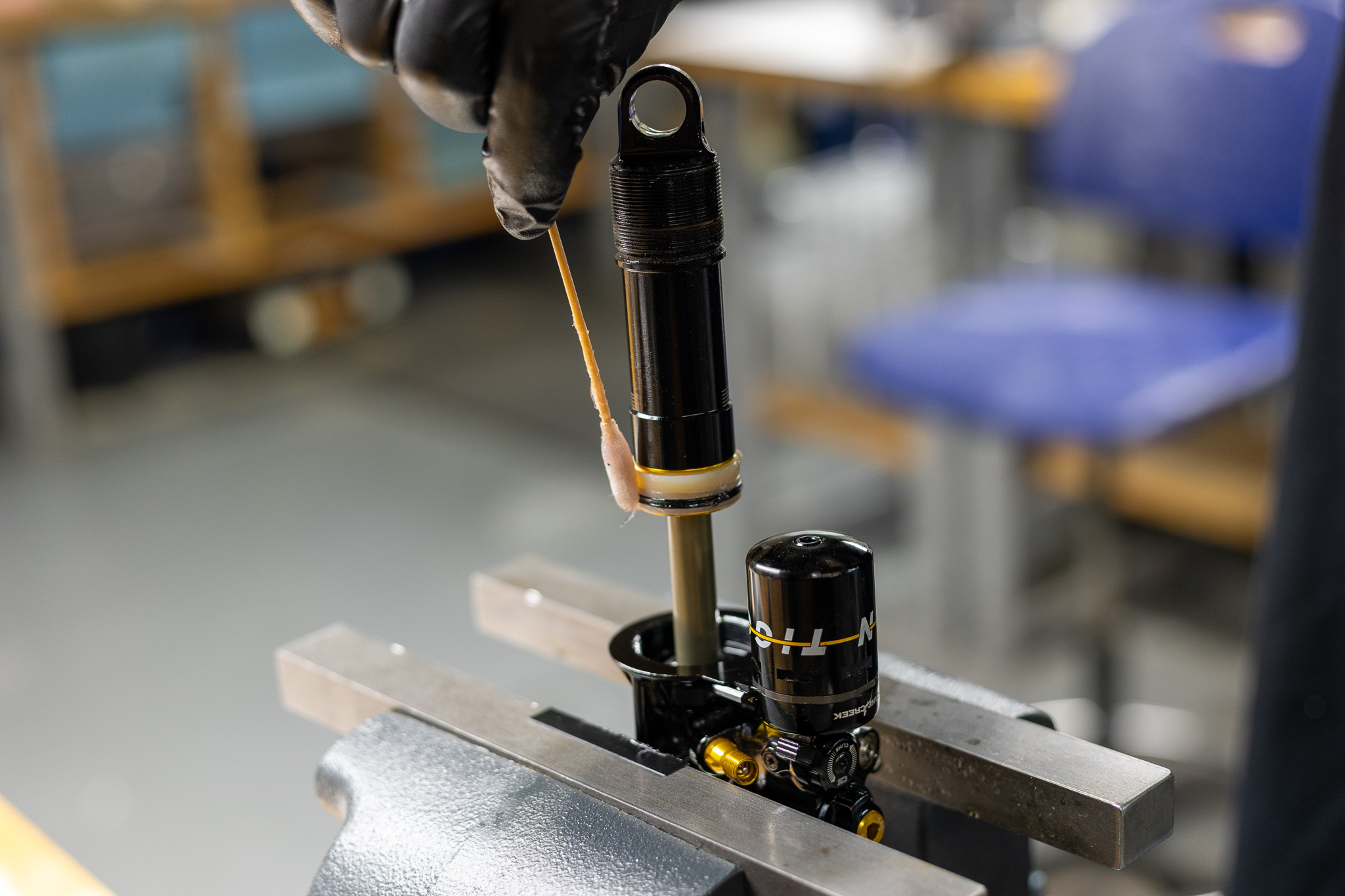
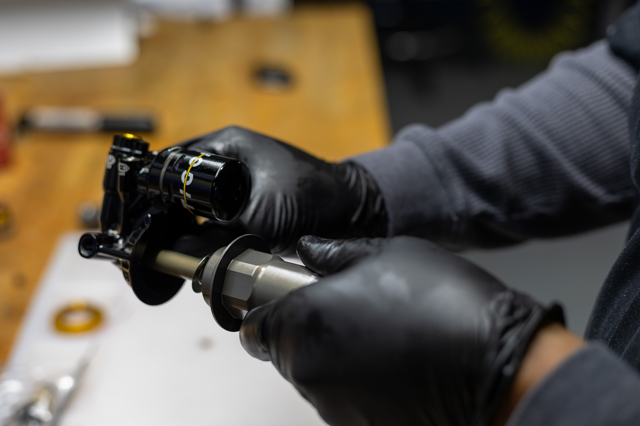
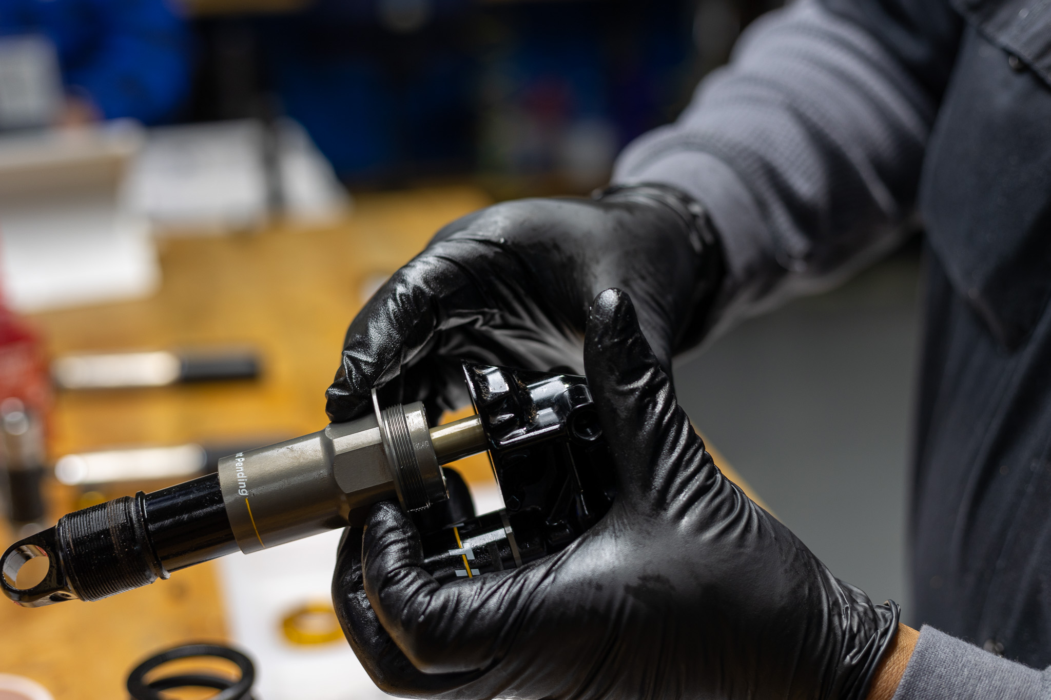
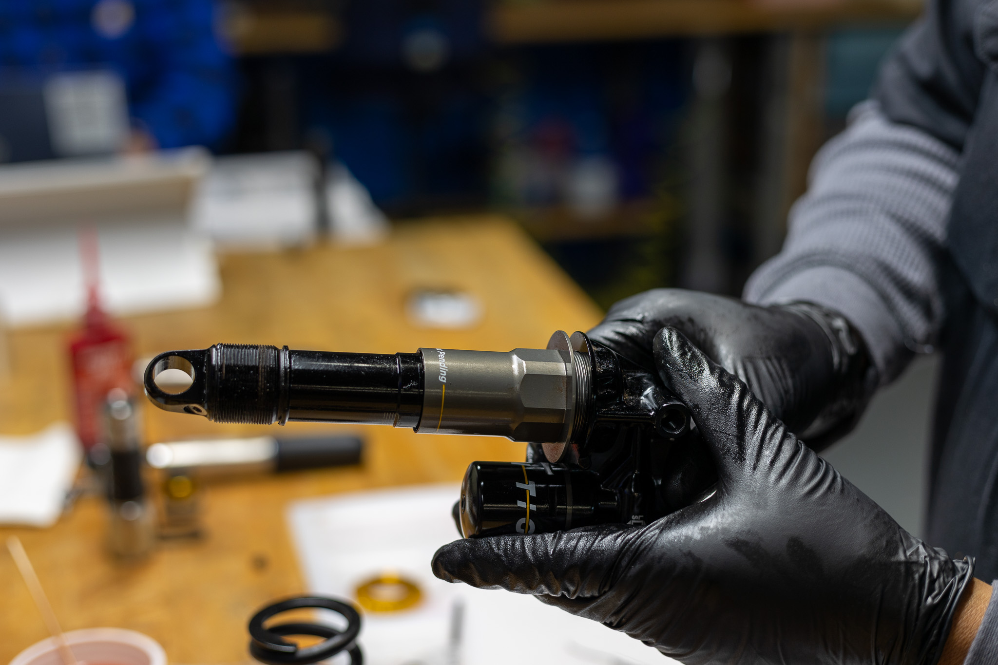
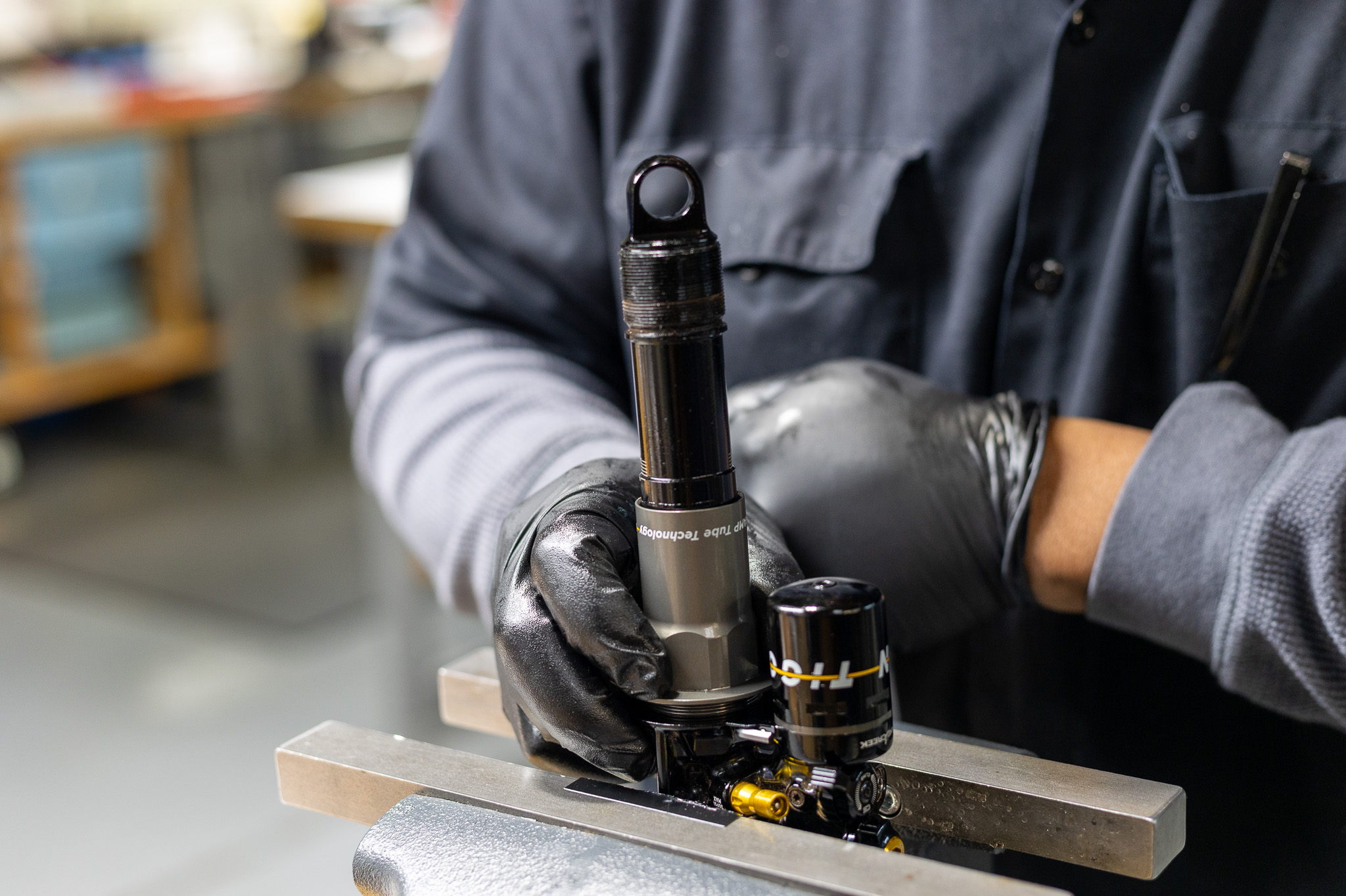
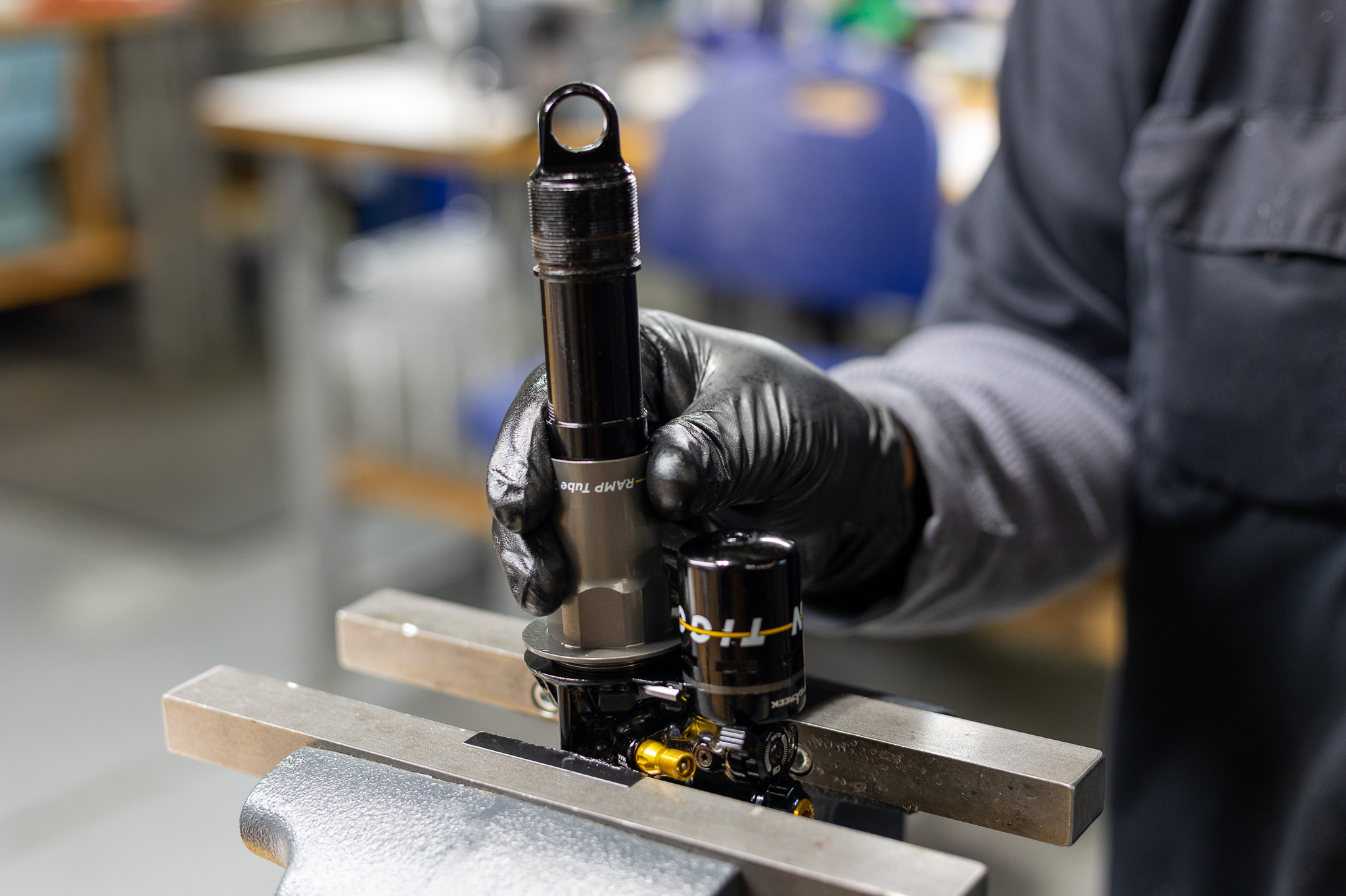
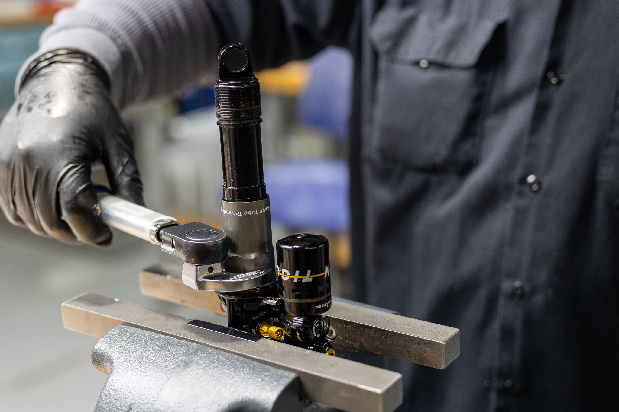
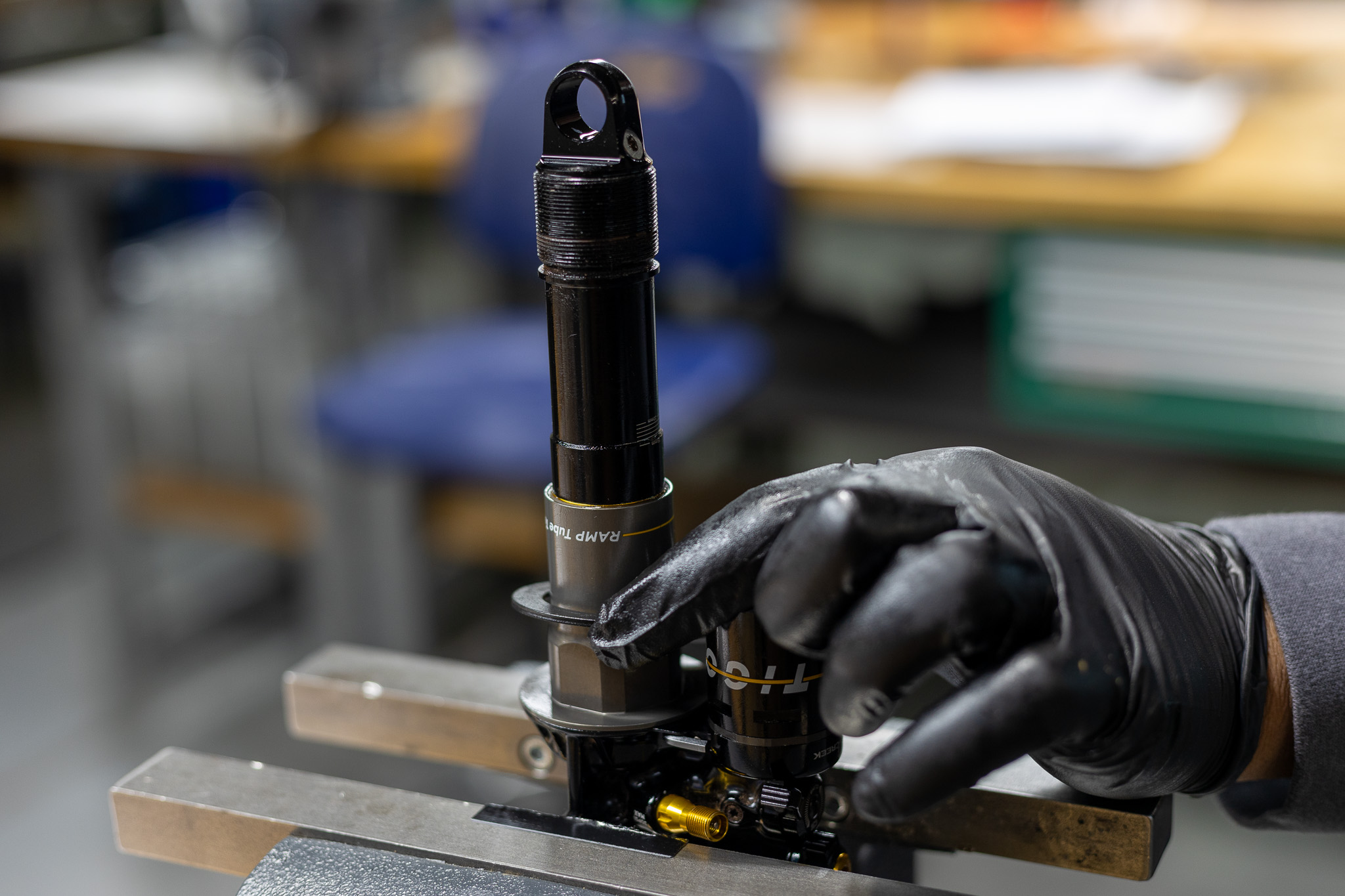
Lightly grease inner rim of RAMP tube and outer edge of oil seal head. Install RAMP tube on damper tube, using a pick to work RAMP tube past oil seal head. Install stroke reduction if needed. Be sure to seat fin on reduction in valve body properly. Clamp valve body in soft jaw vise. Using 34mm crowsfoot, tighten RAMP tube onto valve body to 14.5 Nm.
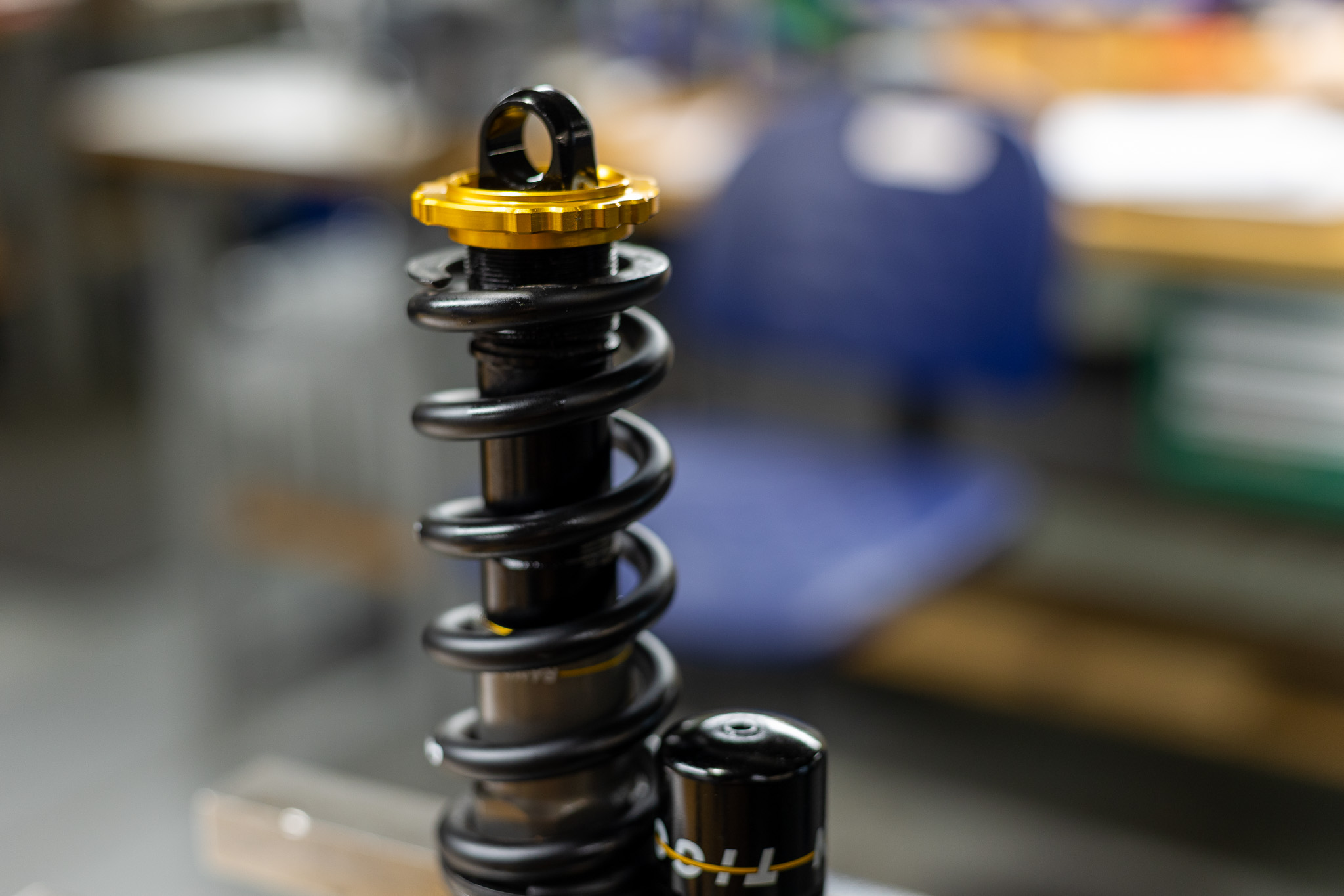
Set adjusters to factory neutral. Using hand dyno, test shock for function. Ensure Climb Switch engages and operates properly. Turn individual adjusters to test each one. Set back to original tune if desired.

Monday: 10:00 am – 5:00 pm
Tuesday – Thursday: 10:00 am – 7:00 pm
Friday: 10:00 am – 5:00 pm
Saturday – Sunday: Closed