PayPal now available at checkout
Free US Shipping On Orders $99+
Previous slide
Next slide
Mar 2022 orig., Jul 2023 rev.
Please dispose of all waste products and materials through proper channels to avoid contamination of the environment.
Any damage or issues resulting from improper service will not be covered by warranty. If you have a shock still in its original warranty period and do not wish to void your warranty, please contact an authorized Cane Creek service center.
These service instructions cover the basic service procedures using standard service kits. If your suspension requires parts beyond standard replacement parts – shaft, damper tubes, end eyes – please consult your authorized Cane Creek service center or contact us at our Cane Creek Support Center.
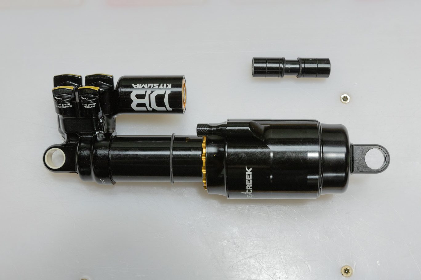
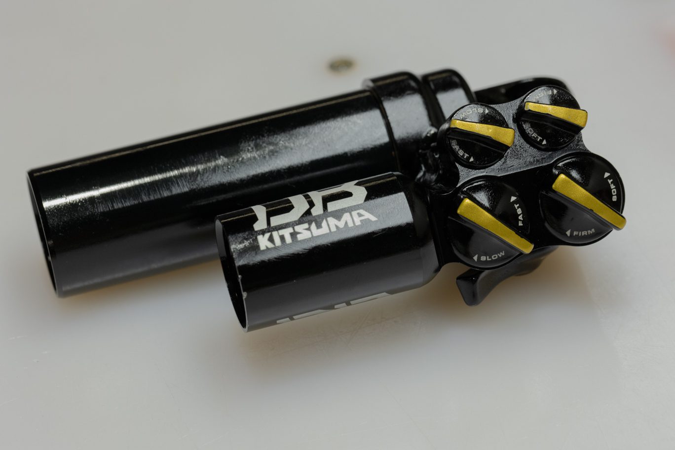
The Kitsuma Air and Coil share many service steps. Additionally, the Standard and Trunnion variants of both models have identical service procedures other than where to clamp the cylinder head. Some images in these instructions may not be identical to the valve body or outer damper tube on the Kitsuma Air, but process is the same for the shock in the image and the shock on your bench.
100 vs. 200 hour service
The only difference between the 100 hour service and the 200 hour service is whether to service or replace the Air Oil Seal Head and the Main Oil Piston. At 100 hours, those can be cleaned, serviced and reinstalled. At 200 hours, they should be replaced. If uncertain on hours, check for wear on the dual bushings inside the Air Oil Seal Head and on the piston band on the Main Oil Piston. When in doubt, replace both.
BCD0337 – Kitsuma Air Complete 100 Hour Rebuilt Kit (w/ Bladder)
OR
BCD0339-01 – Kitsuma Air Complete 200 Hour Rebuild Kit (w/ Bladder) – includes new Air Oil Seal Head & Main Oil Piston
BCD0169 – Bladder Res End Cap (if replacing older IFP system)
ACD0354 – Bladder Res End Fill Tool
AAD1361-01 – DBCoil/ DBAir – Oil Fill Needle Adapter
DBT016 – DB Gas Fill Needle
AAD0555 – 8mm & 9.5mm Shaft Clamp
AAD2465 – Kitsuma Valve Seat Tool
ACD0322 – Kitsuma Low Speed Detent Funnel
BAD1298 – DB 9.5mm Shaft Bullet
ACD0334 – Kitsuma Air Oil Seal Head Tool
BCD0344 – Kitsuma/DBair/DBair IL Air Seal Head Tool
DBT012 – DB IFP Setting Tool
Allen wrenches – 3 & 4mm
Torx wrenches – T10 & T20
Sockets – 4, 8 & 13mm
Crowfoot wrenches – 1/2″ & 32mm
9.5mm Shaft Bullet
Torque wrenches
Knipex pliers
Pick
Strap wrench
Suspension Grease
PolyLube Grease
Motorex 4wt Racing Fork Oil
Royal Purple 10w-30
Vacuum Oil Fill Machine
Nitrogen Fill System
Torque & Loctite Chart
| Part | Torque Spec | Loctite Spec |
| Shaft Bolt | 5 Nm | 243 (Blue) |
| Outer Damper Tube | Tight | 263 (Red) |
| Valve Seat | 4.8 Nm | None |
| High Speed Adjuster | 7 Nm | None |
| Climb Switch Screw | 1.2 Nm | 243 (Blue) |
| Oil Seal Head | 22 Nm | None |
| End Eye | 4.8 Nm | 243 (Blue) |
| Inner Air Can/Air Seal Head | 22.6 Nm | None (PolyLube) |
Oil Chart
| Oil Location | Oil Type | Oil Amount |
| Air Can | Royal Purple 10w-30 | 5 mL |
| Damper Fill | Motorex 4wt Racing Fork Oil | Fill to 3 Bars |
Nitrogen Chart
| Nitrogen Location | Nitrogen Pressure |
| Valve Body | 11-12 Bars |
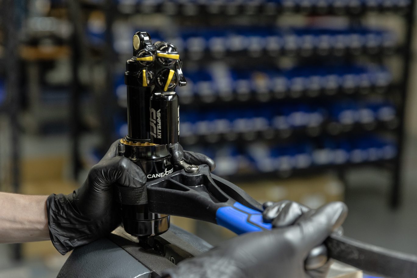
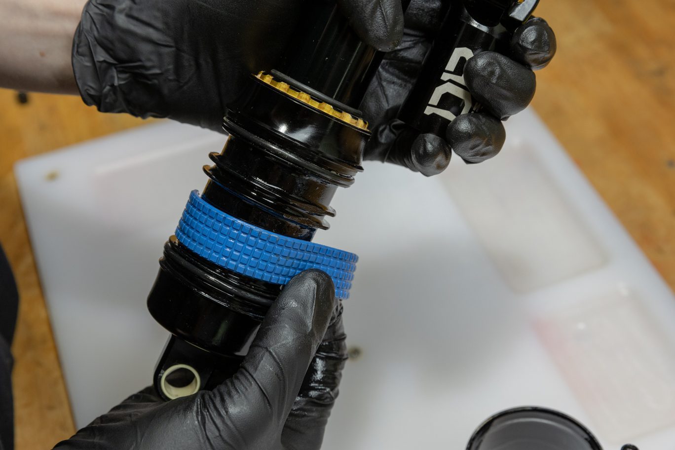
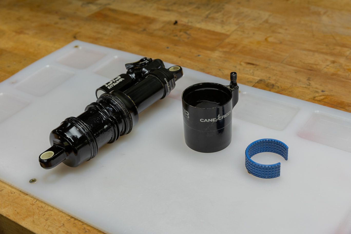
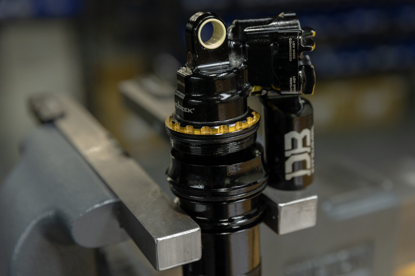
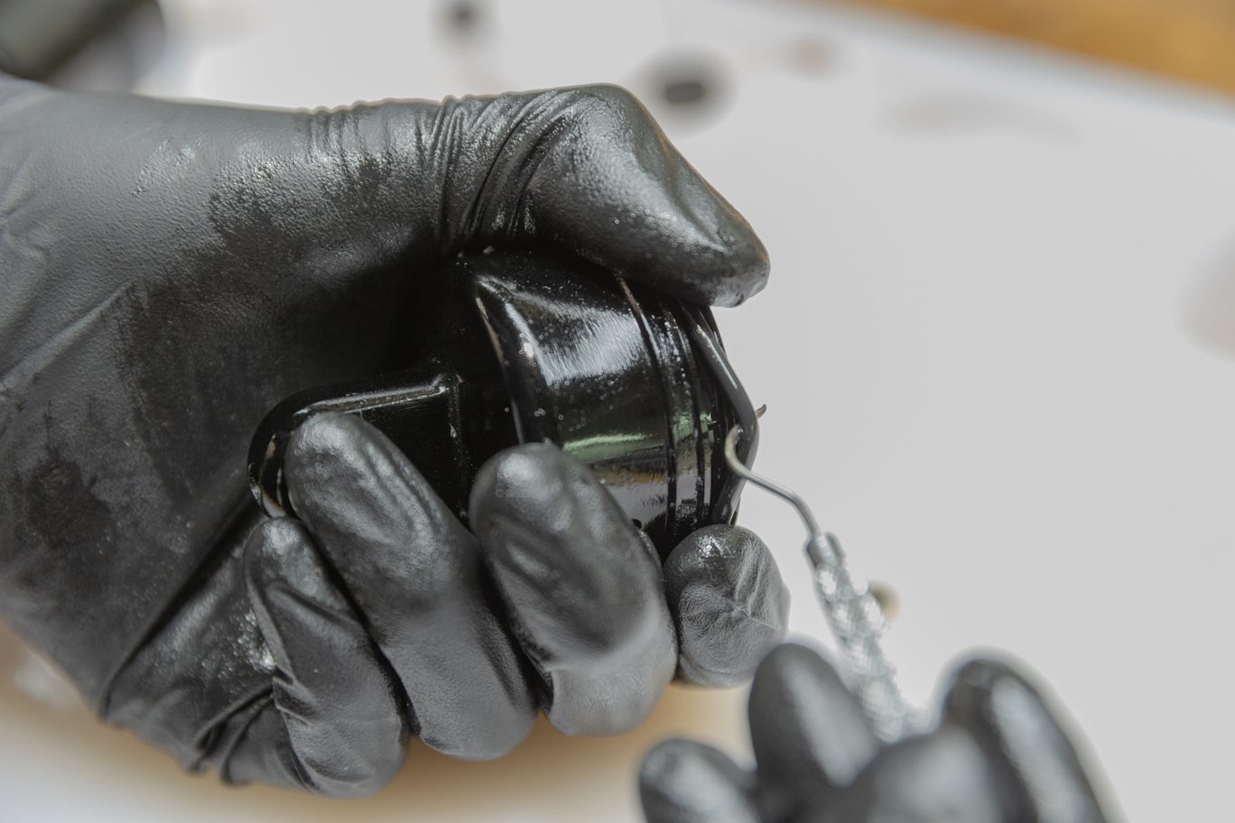
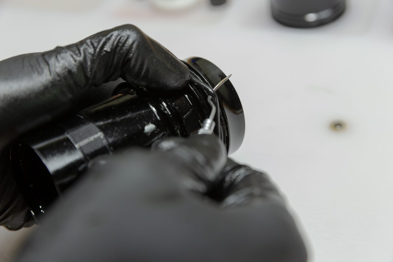
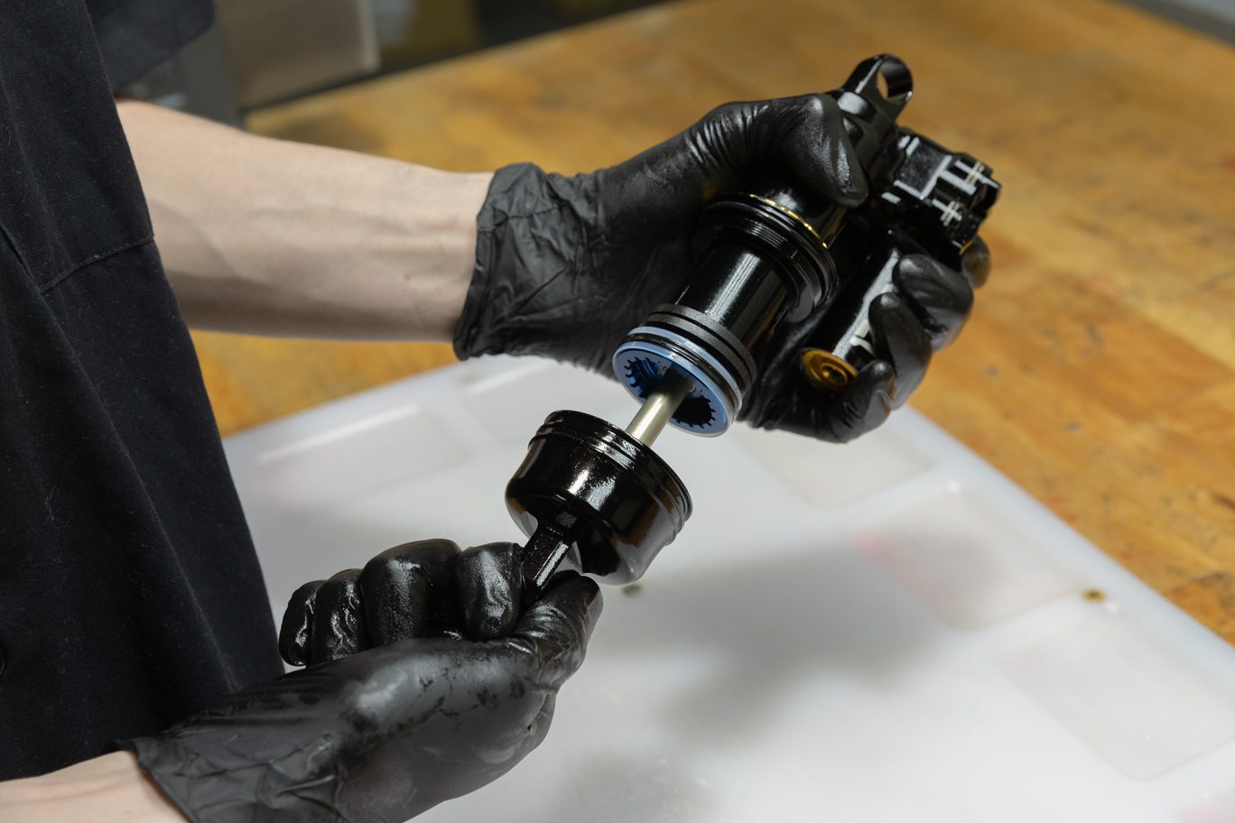
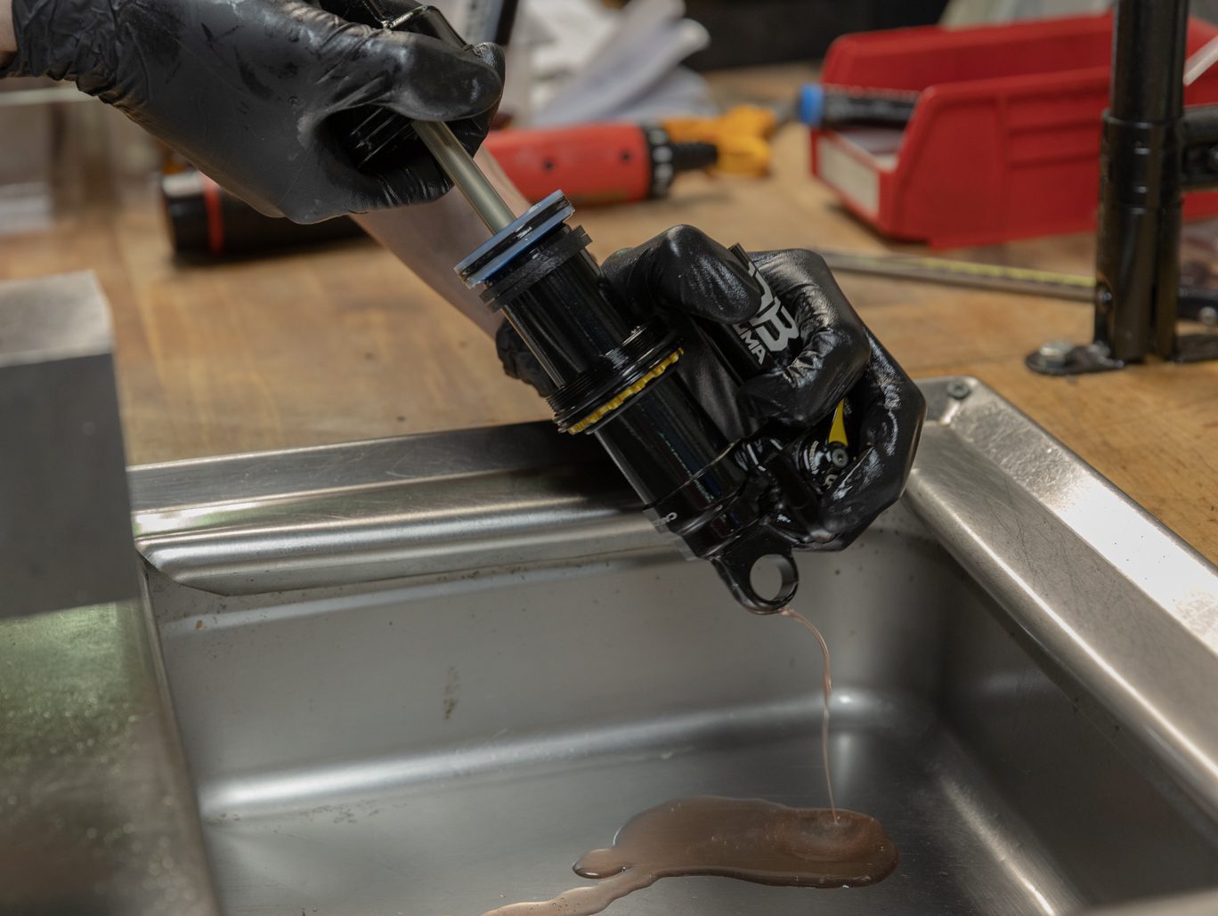
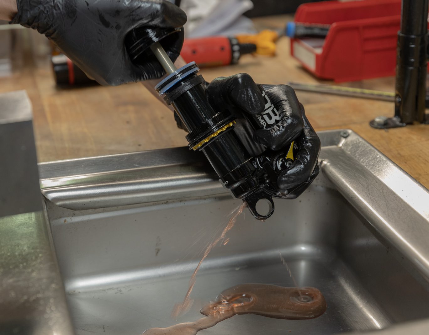
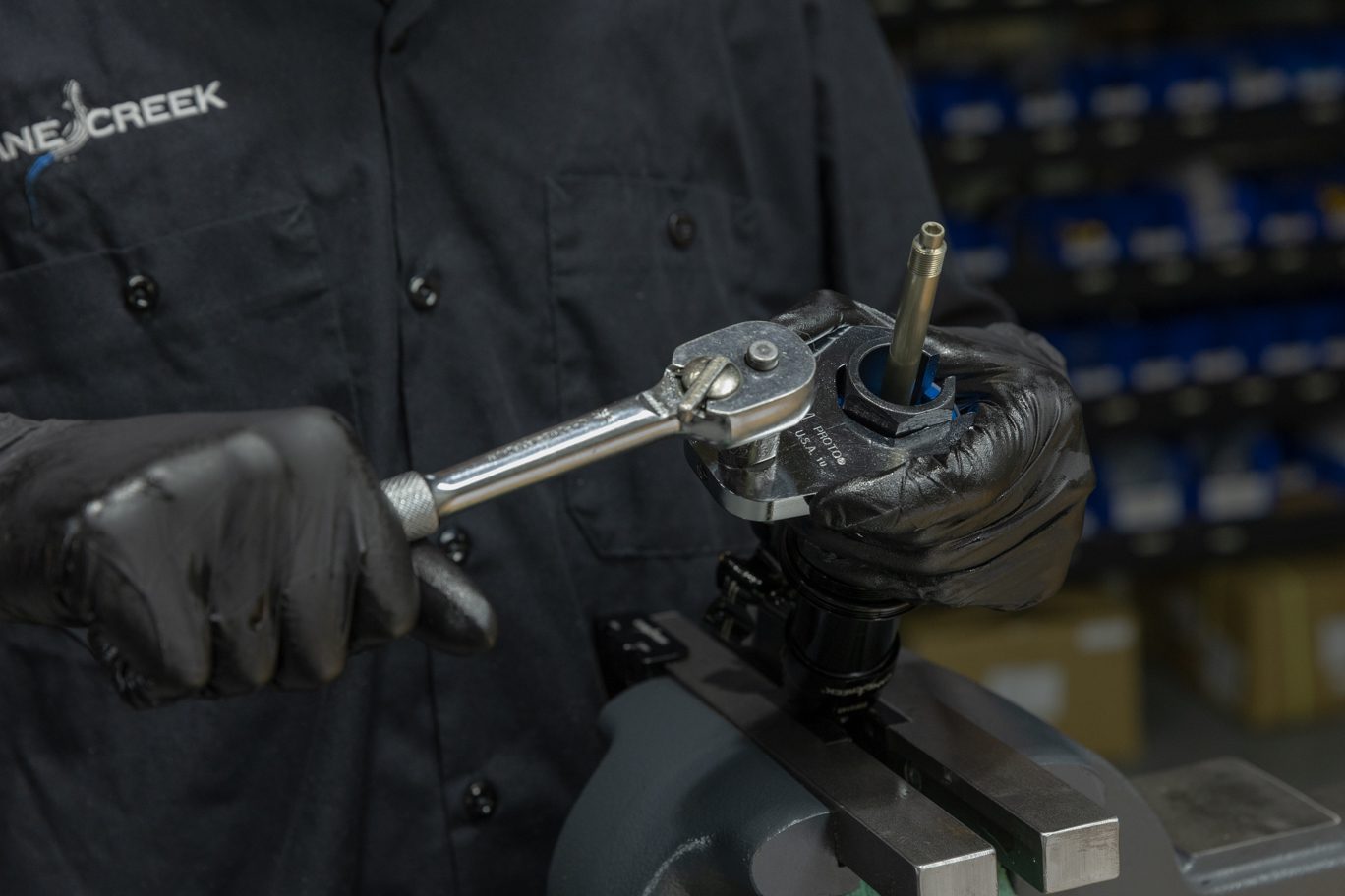
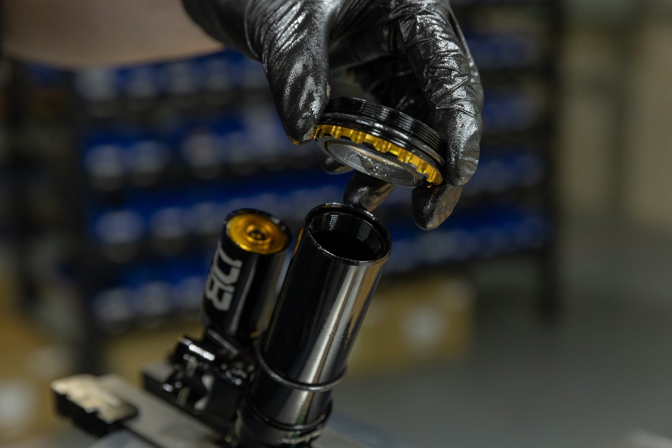
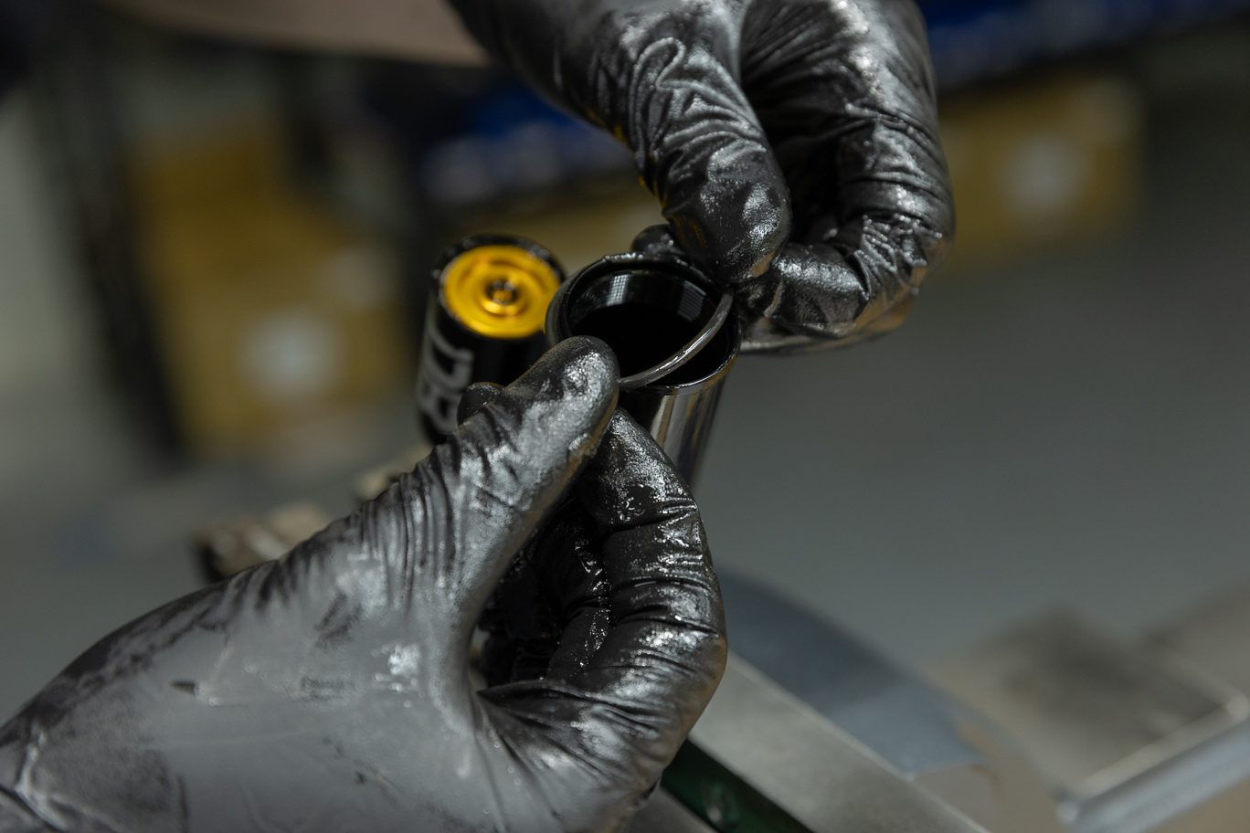
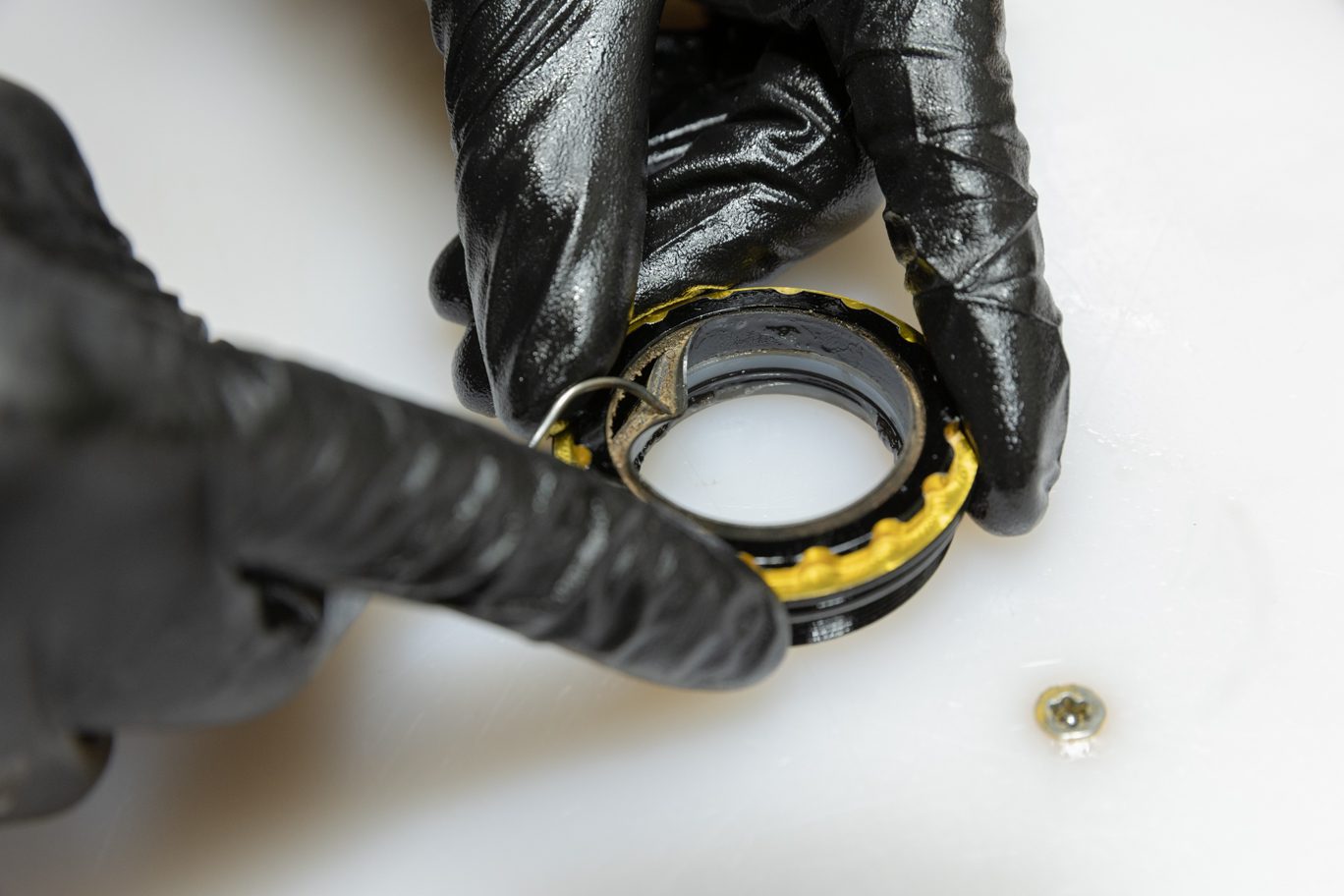
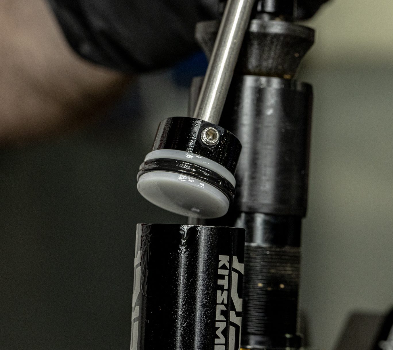
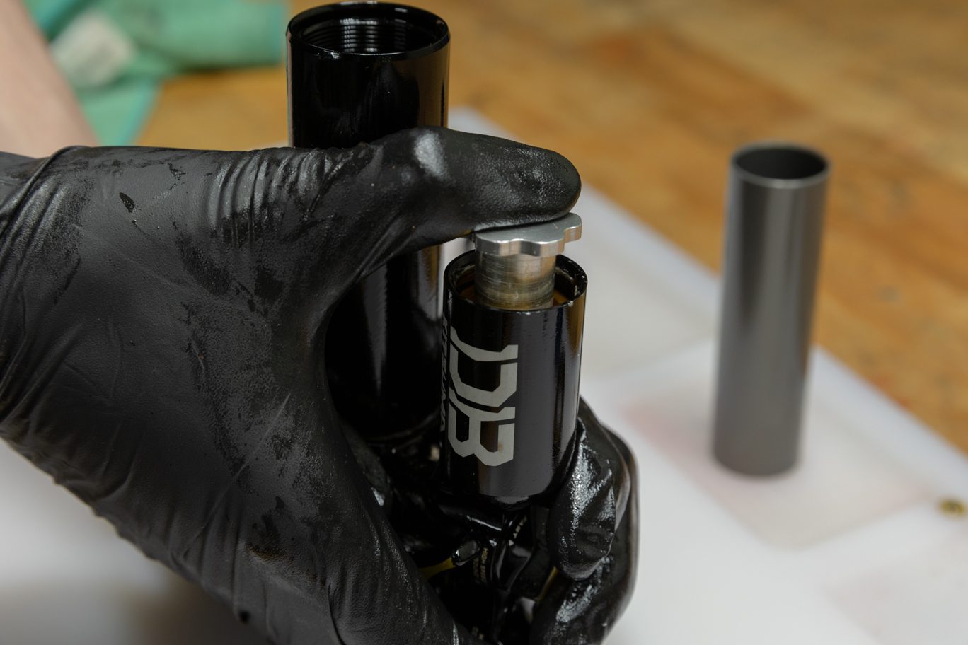
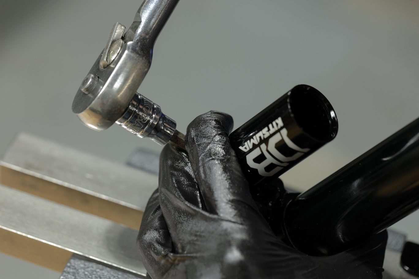
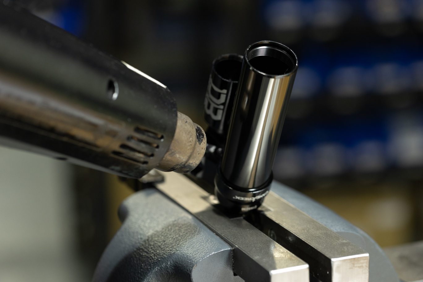
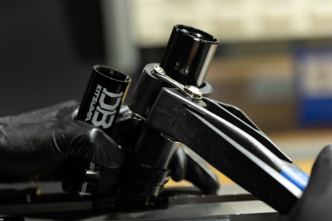
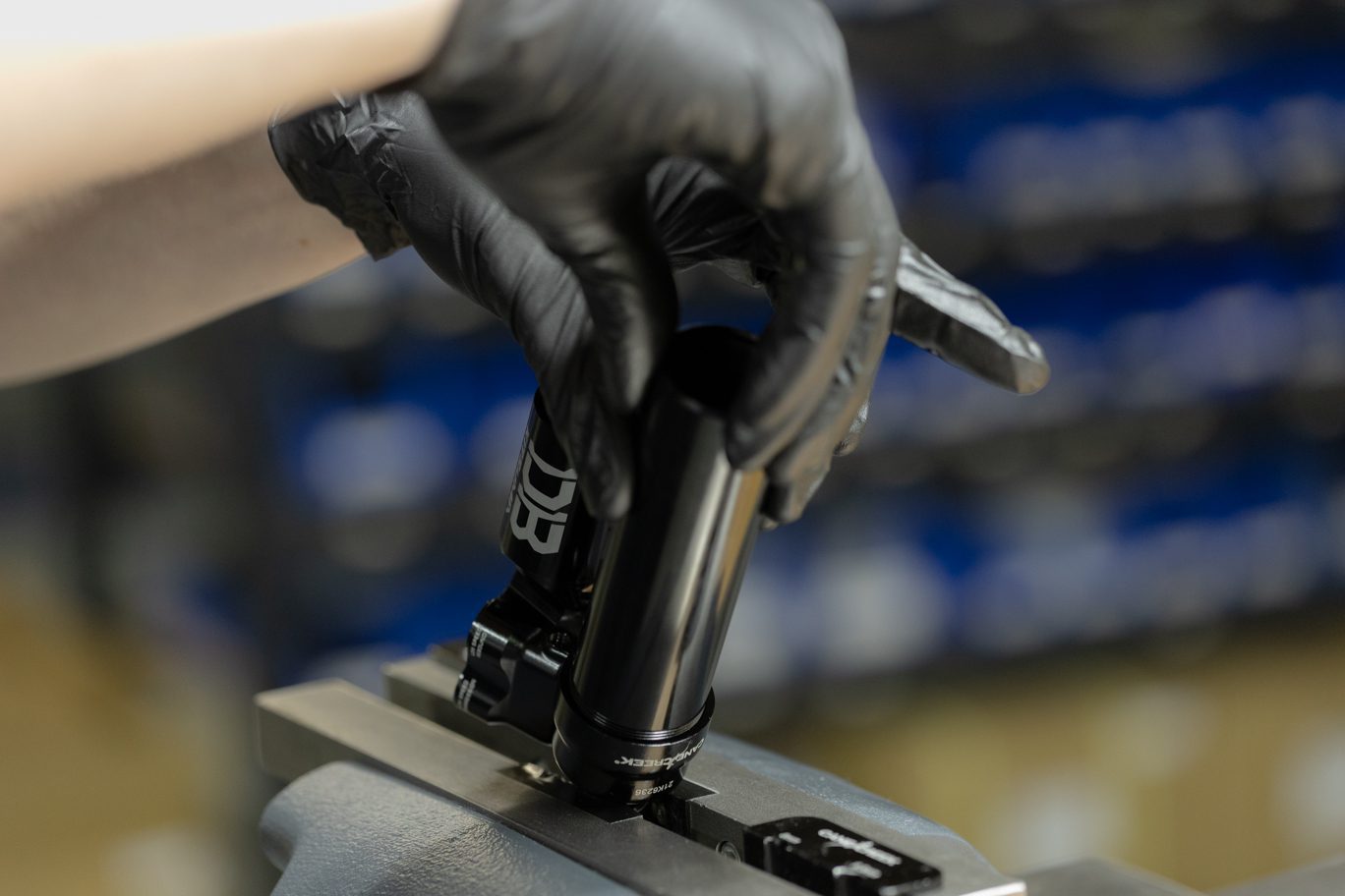
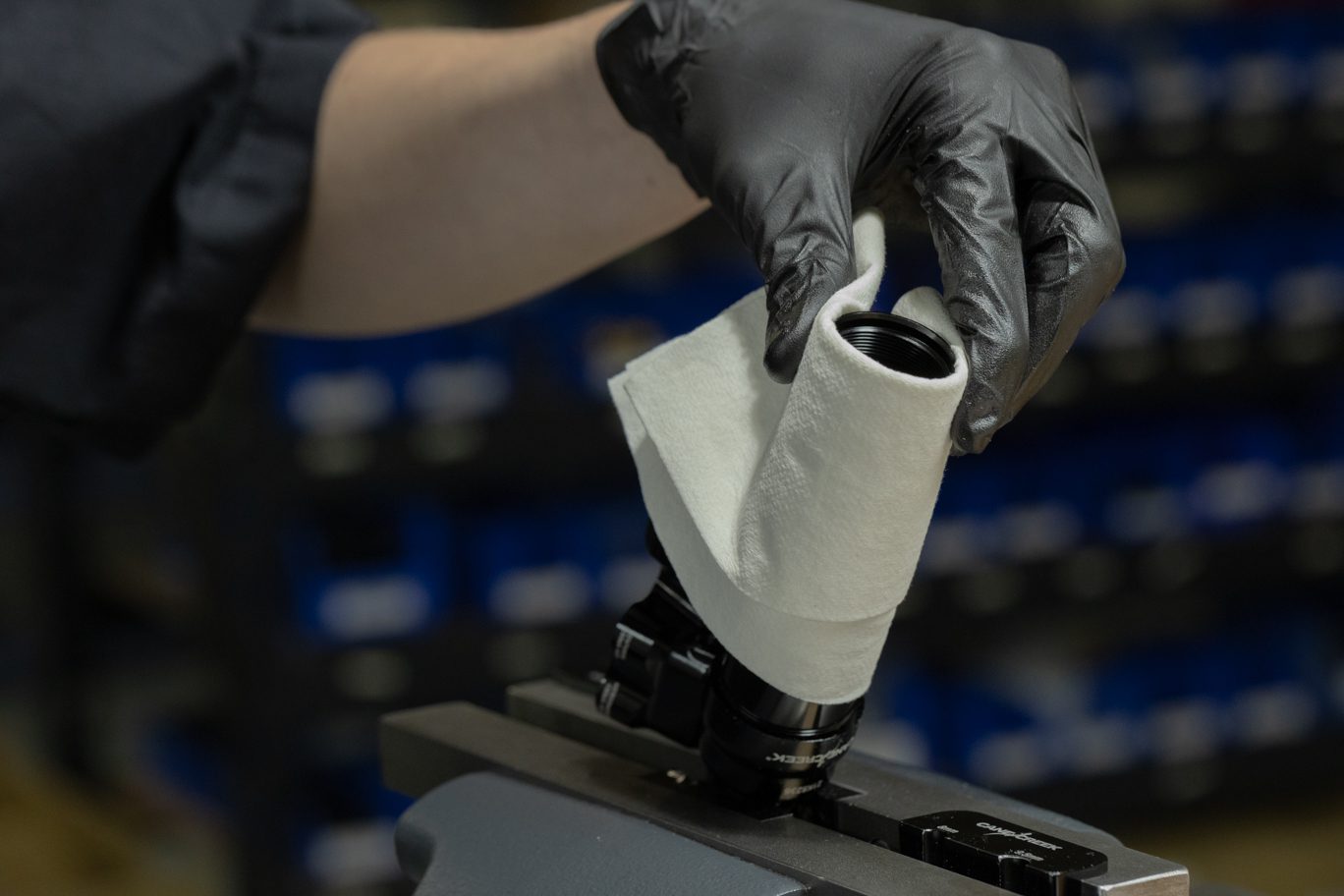
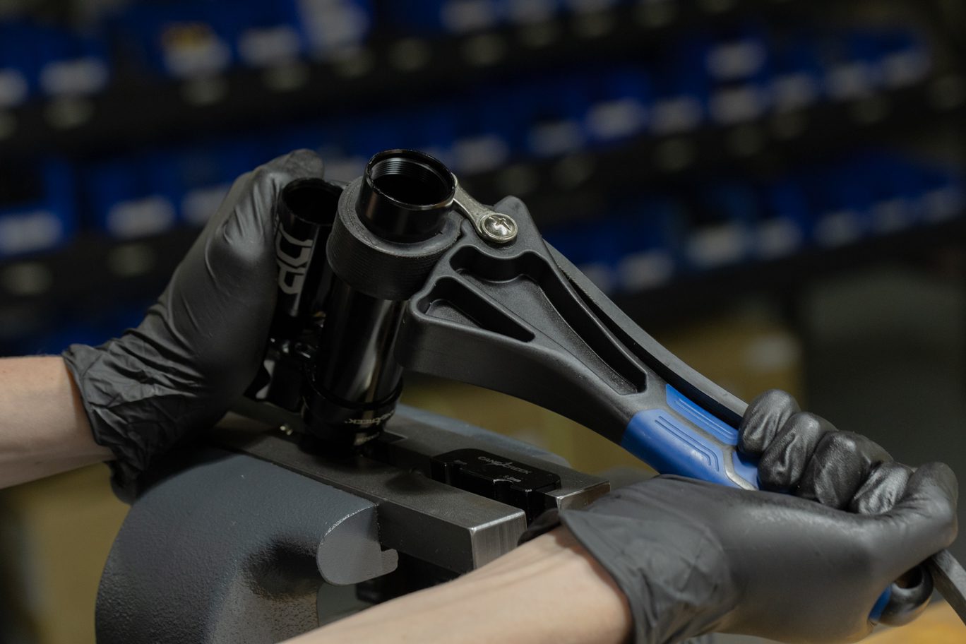
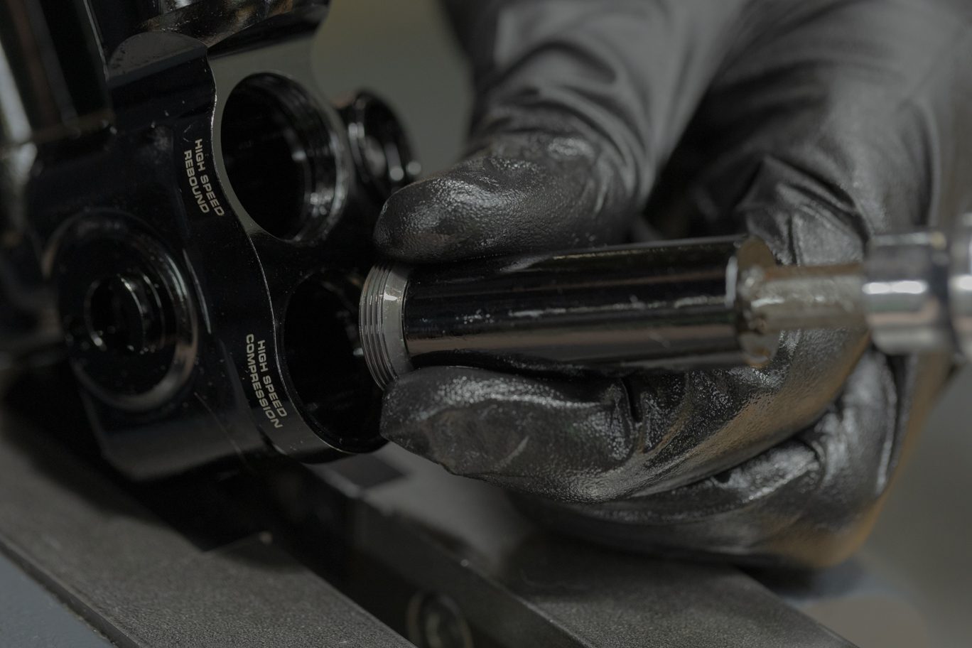
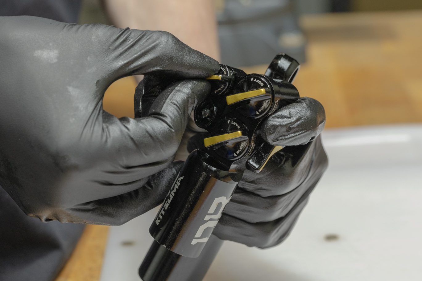
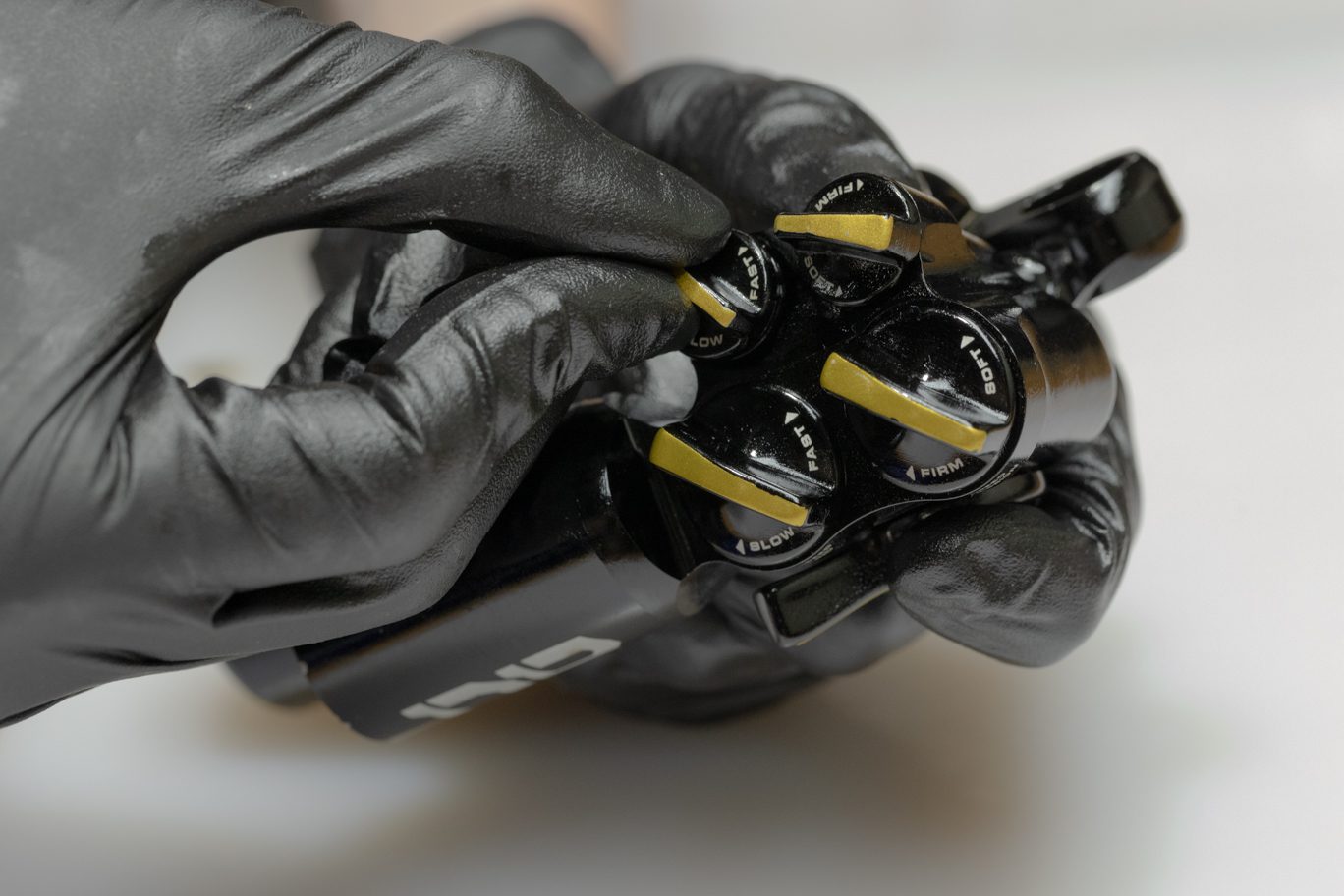
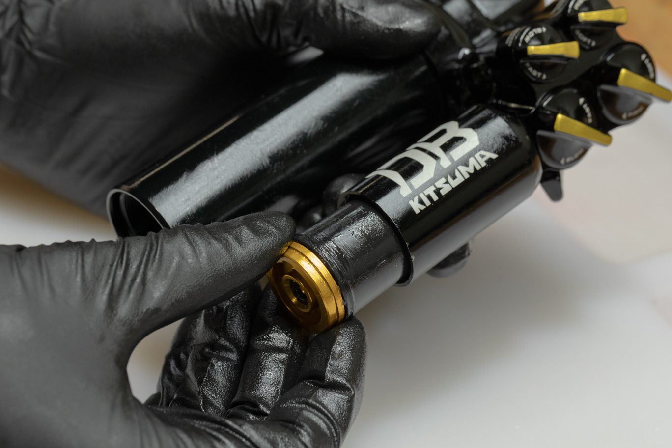
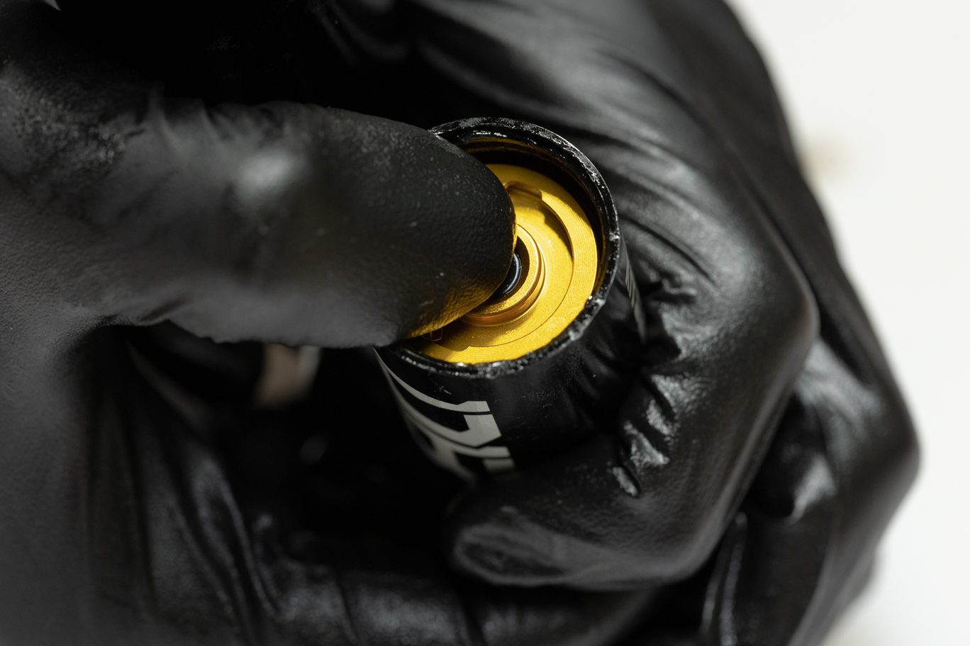
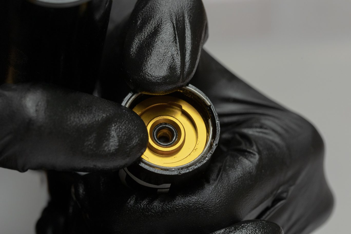
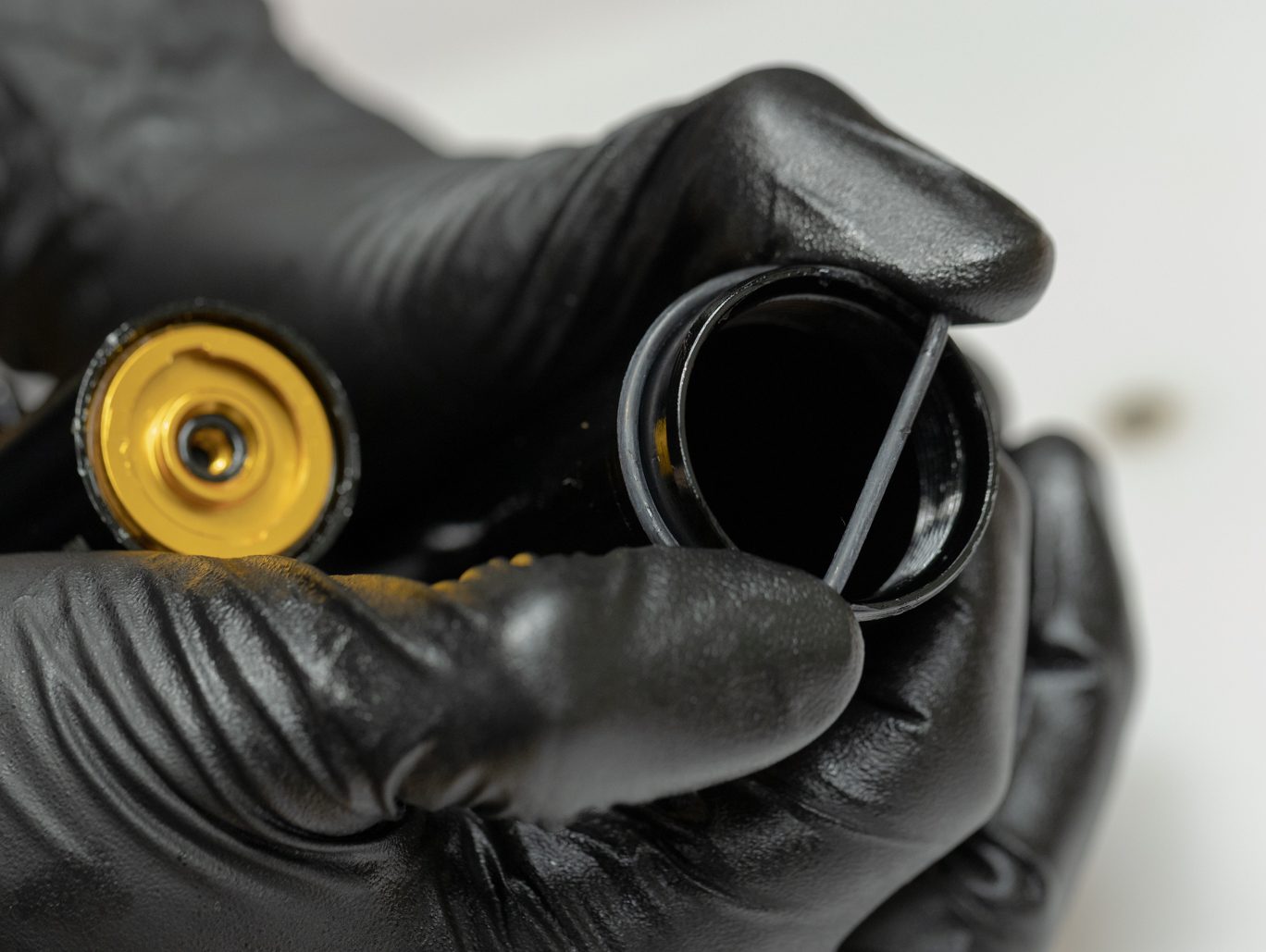
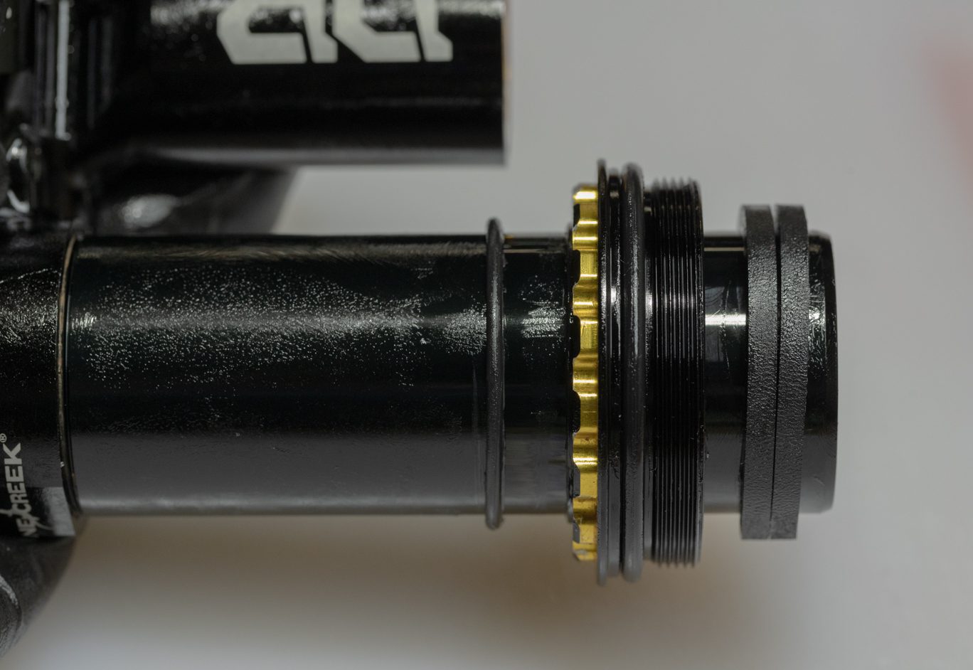
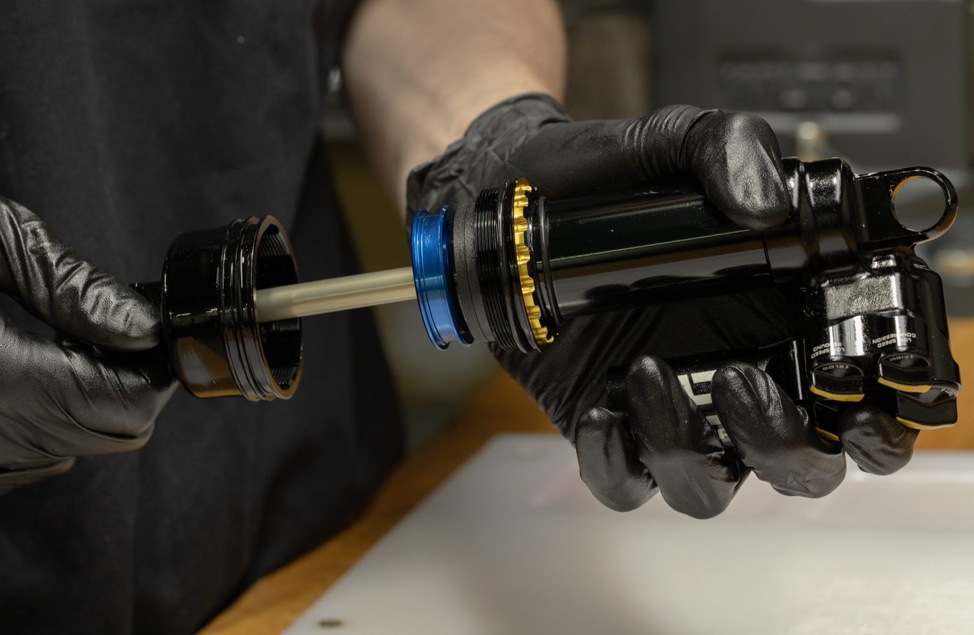
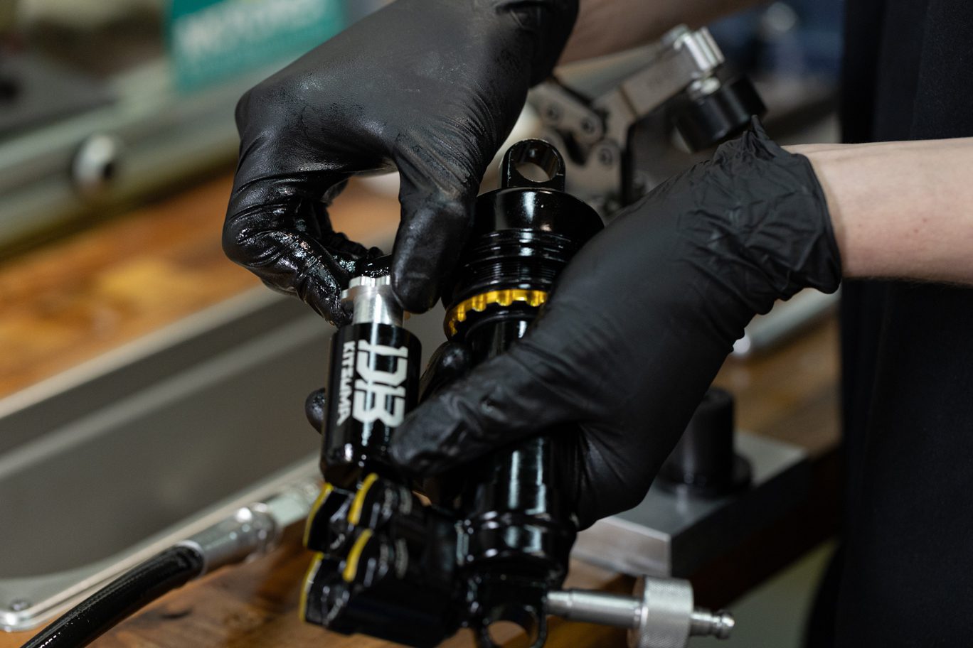
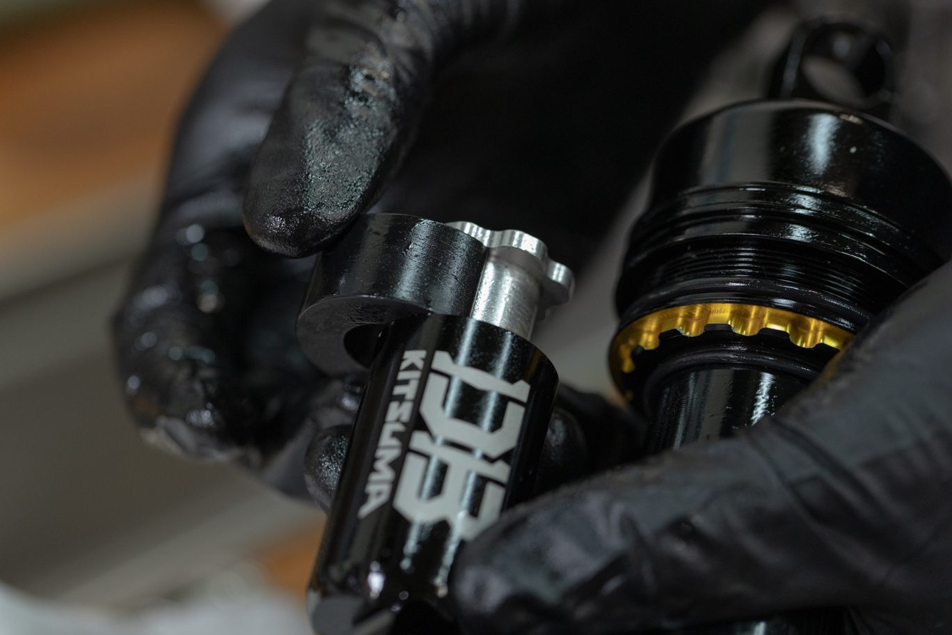
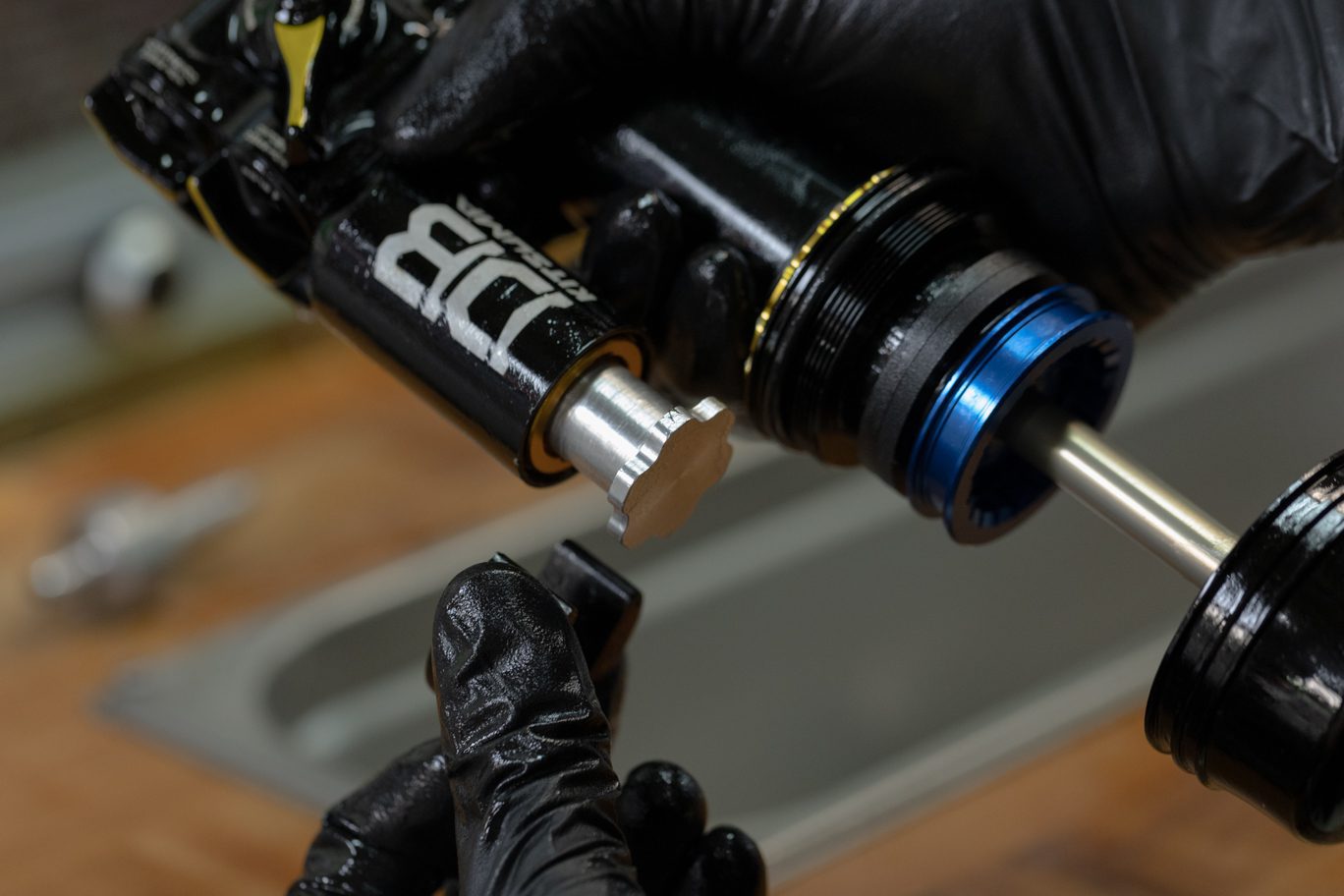
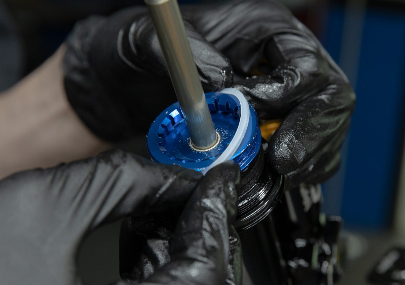
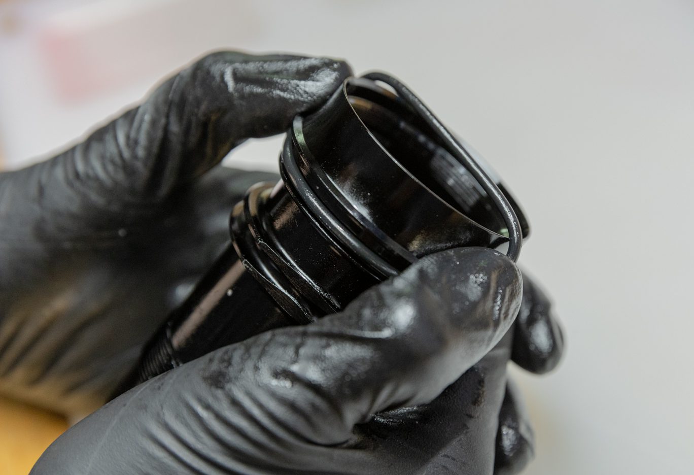
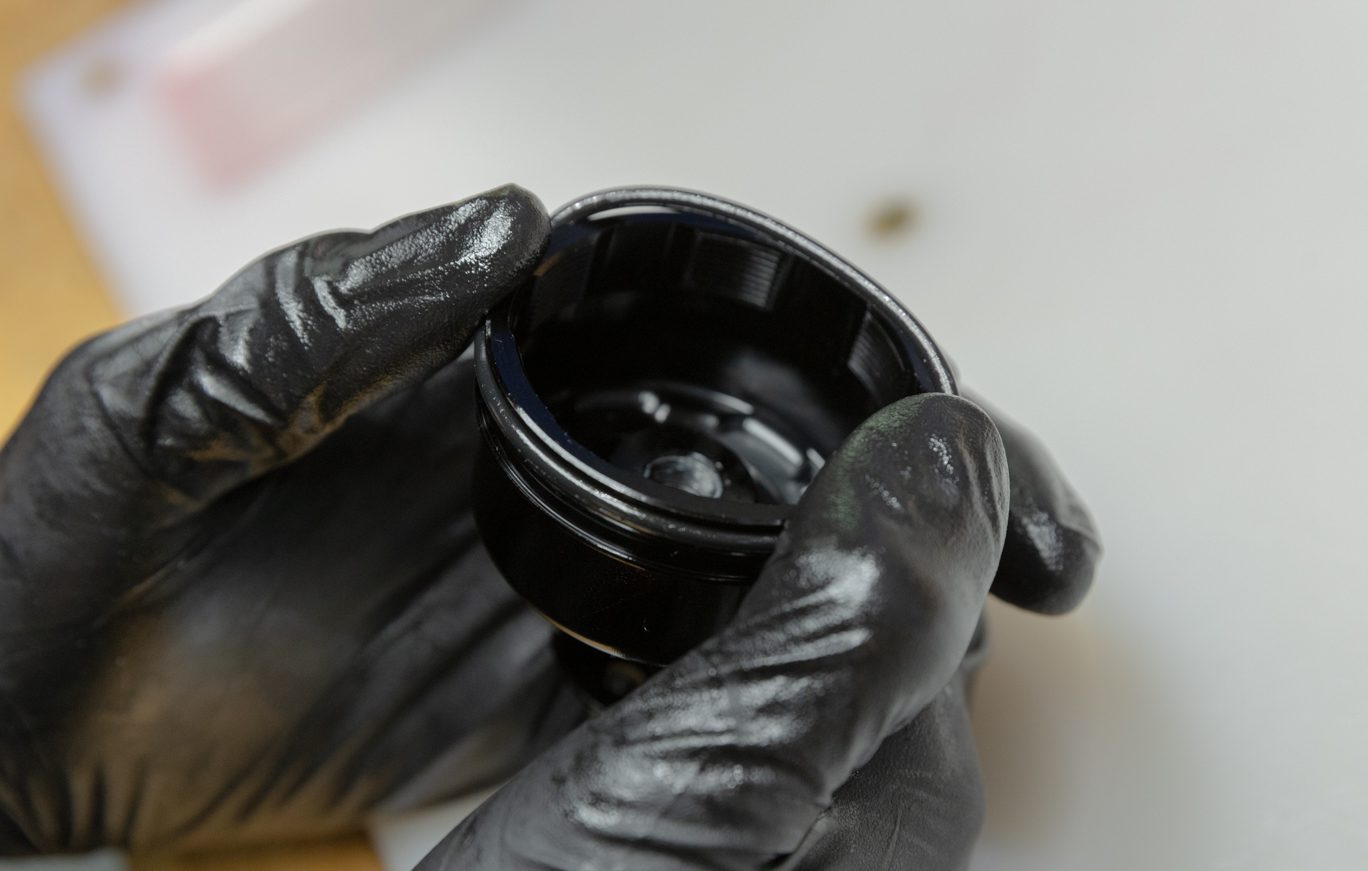
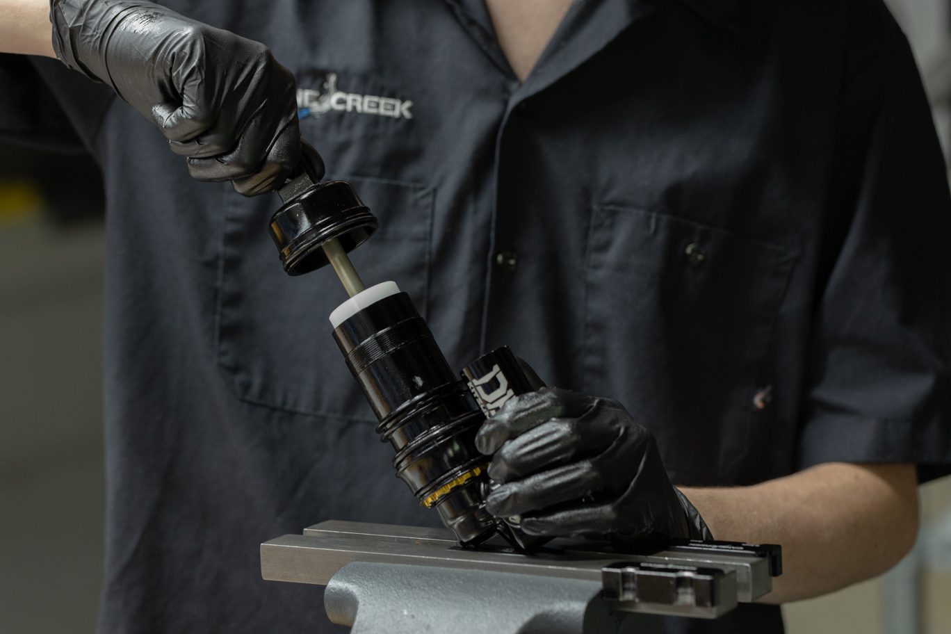
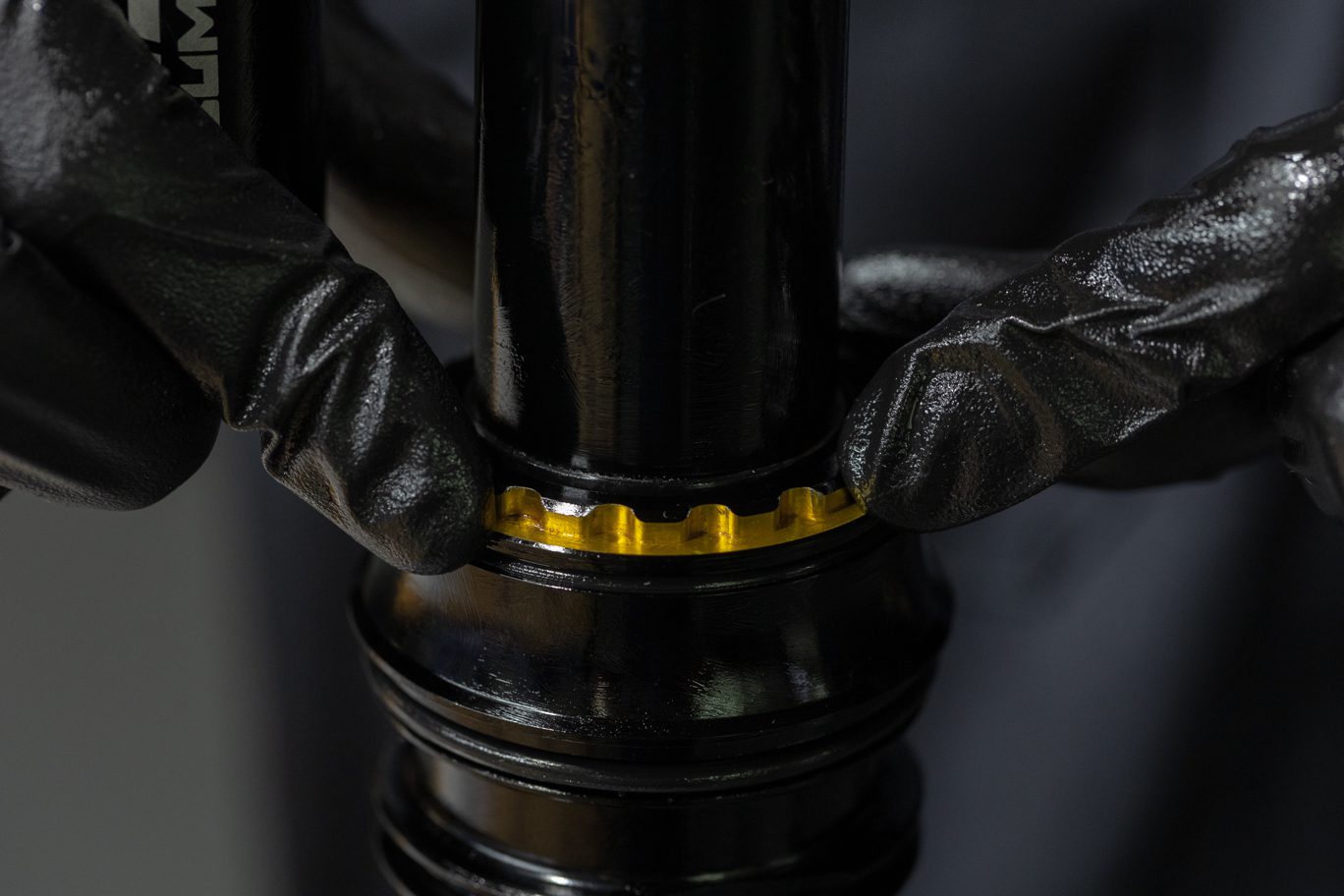
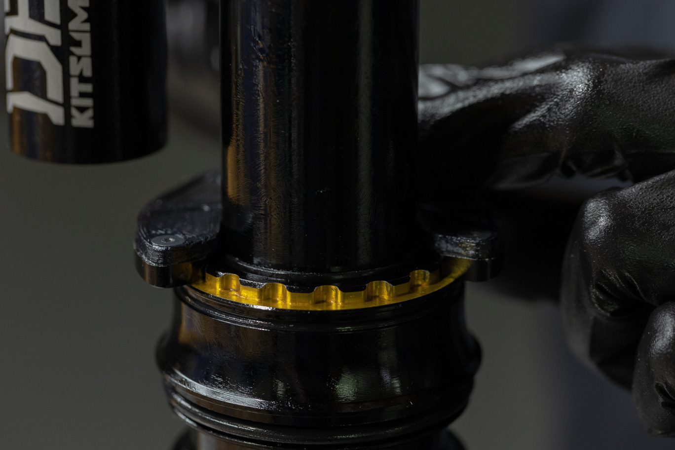
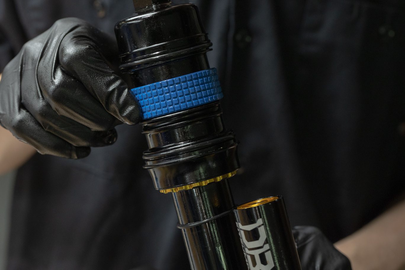
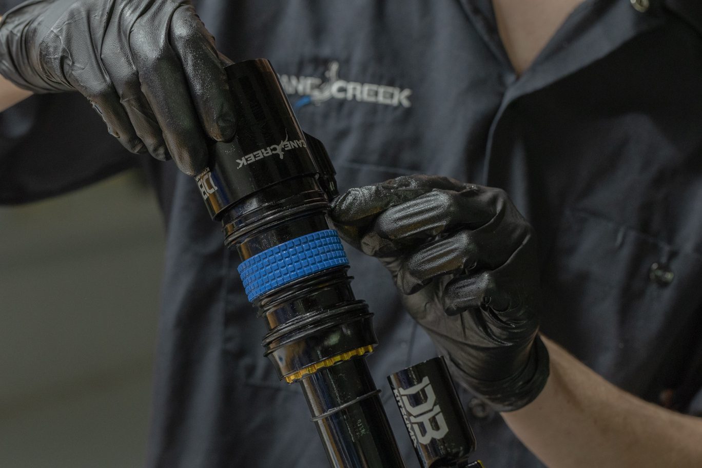
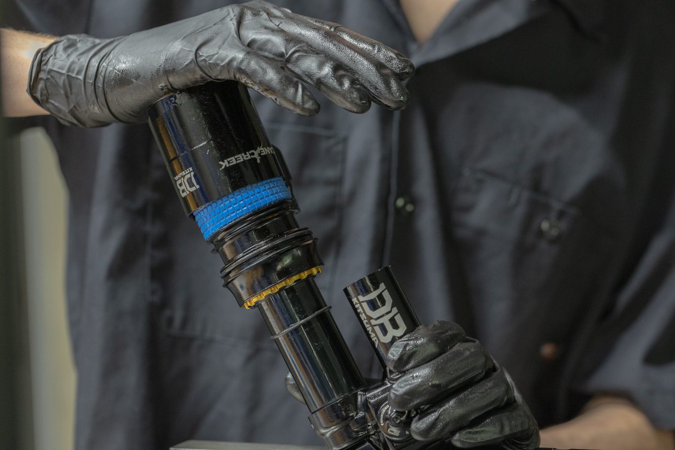
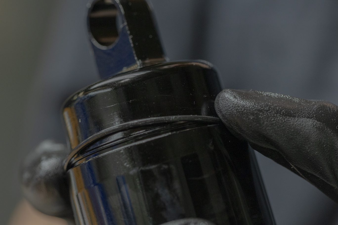
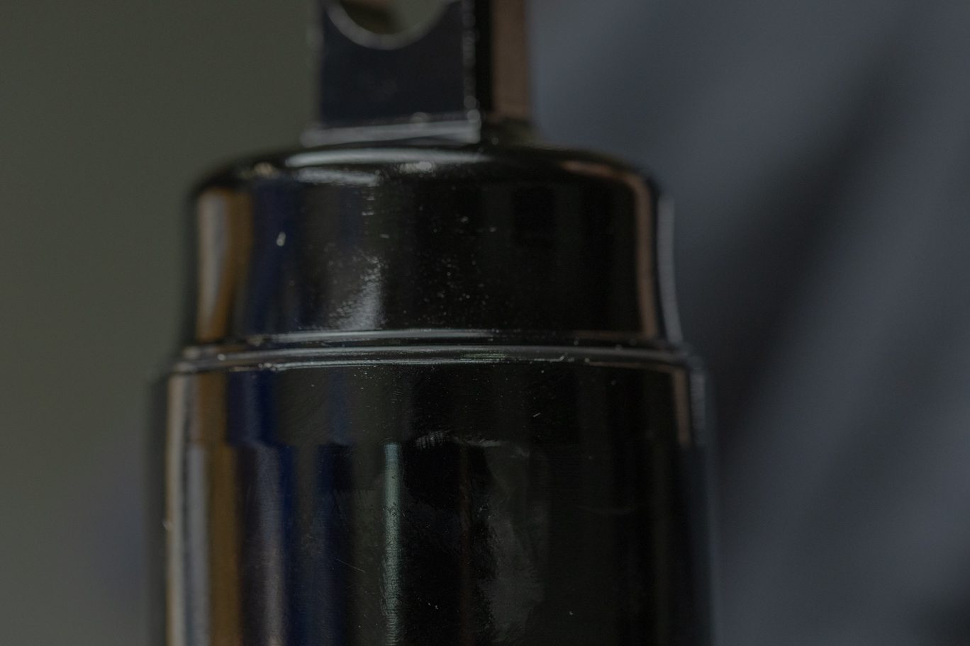
Reclamp shock. Align teeth on Air Seal Head Tool (BCD0344) with grooves on air seal head. Unthread air seal head and inner air can from end eye. Splash oil may be present. Gently clamp inner air can and use air seal head tool to loosen air seal head from inner air can. Take care to not crush inner air can.
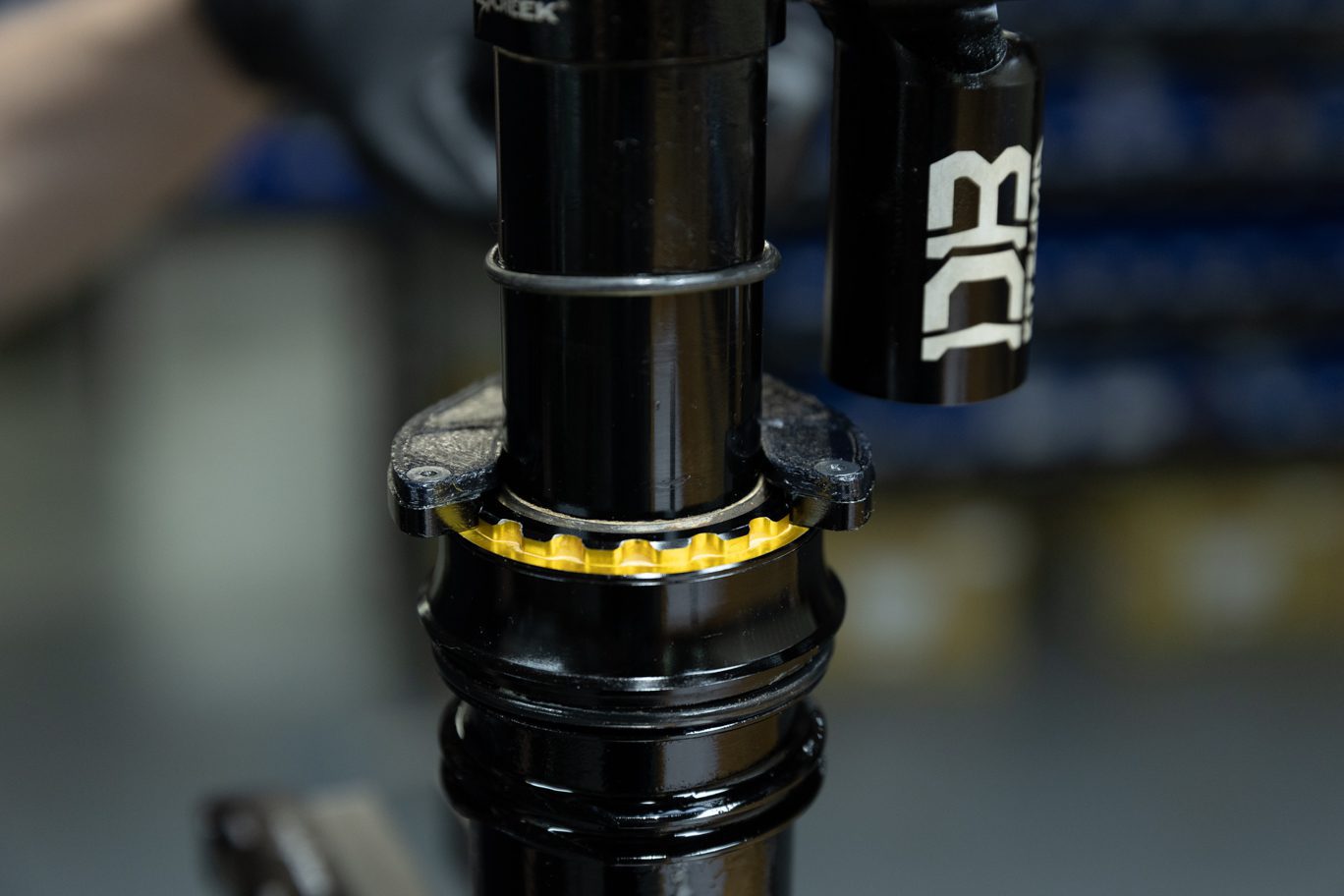
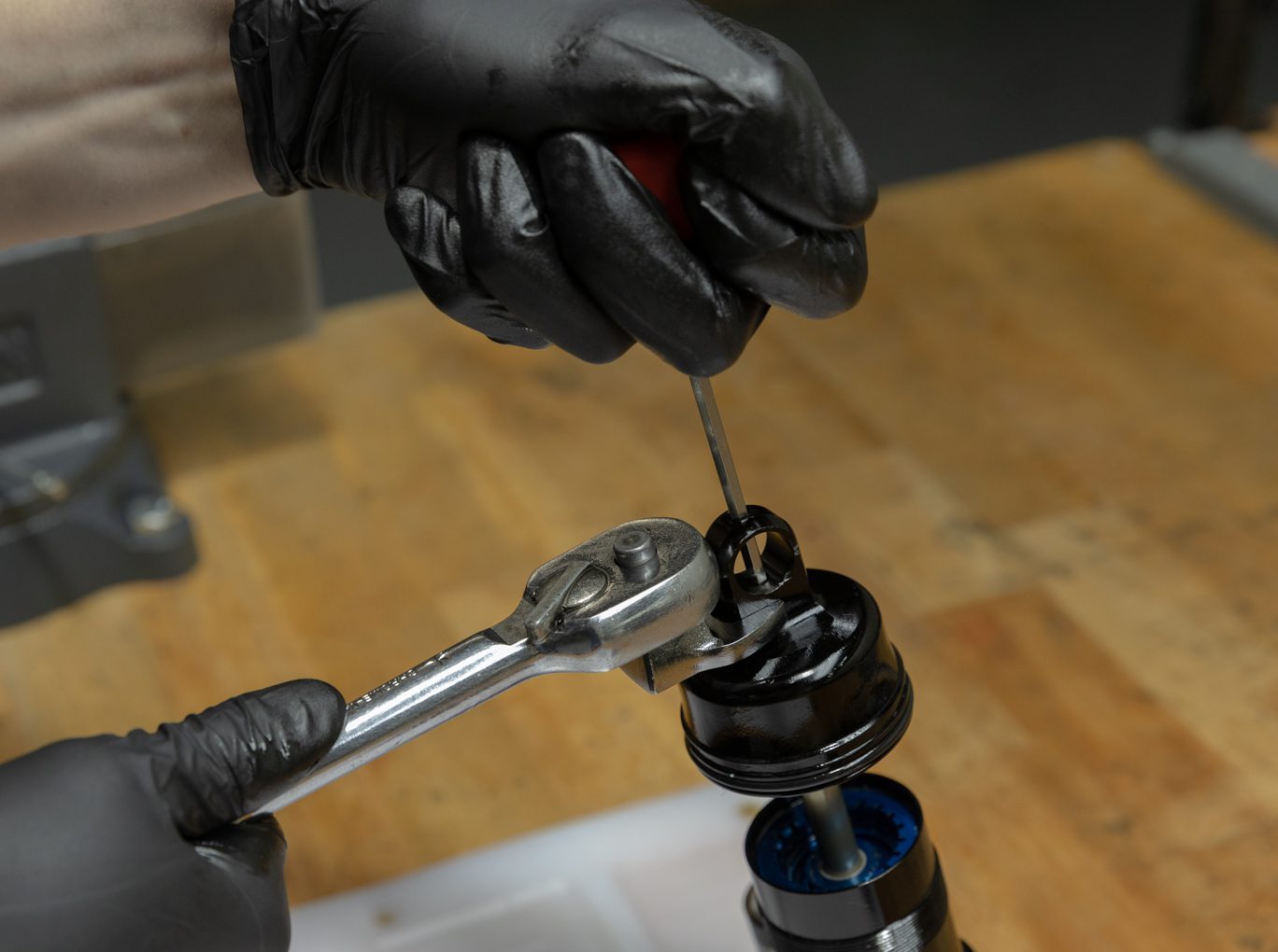
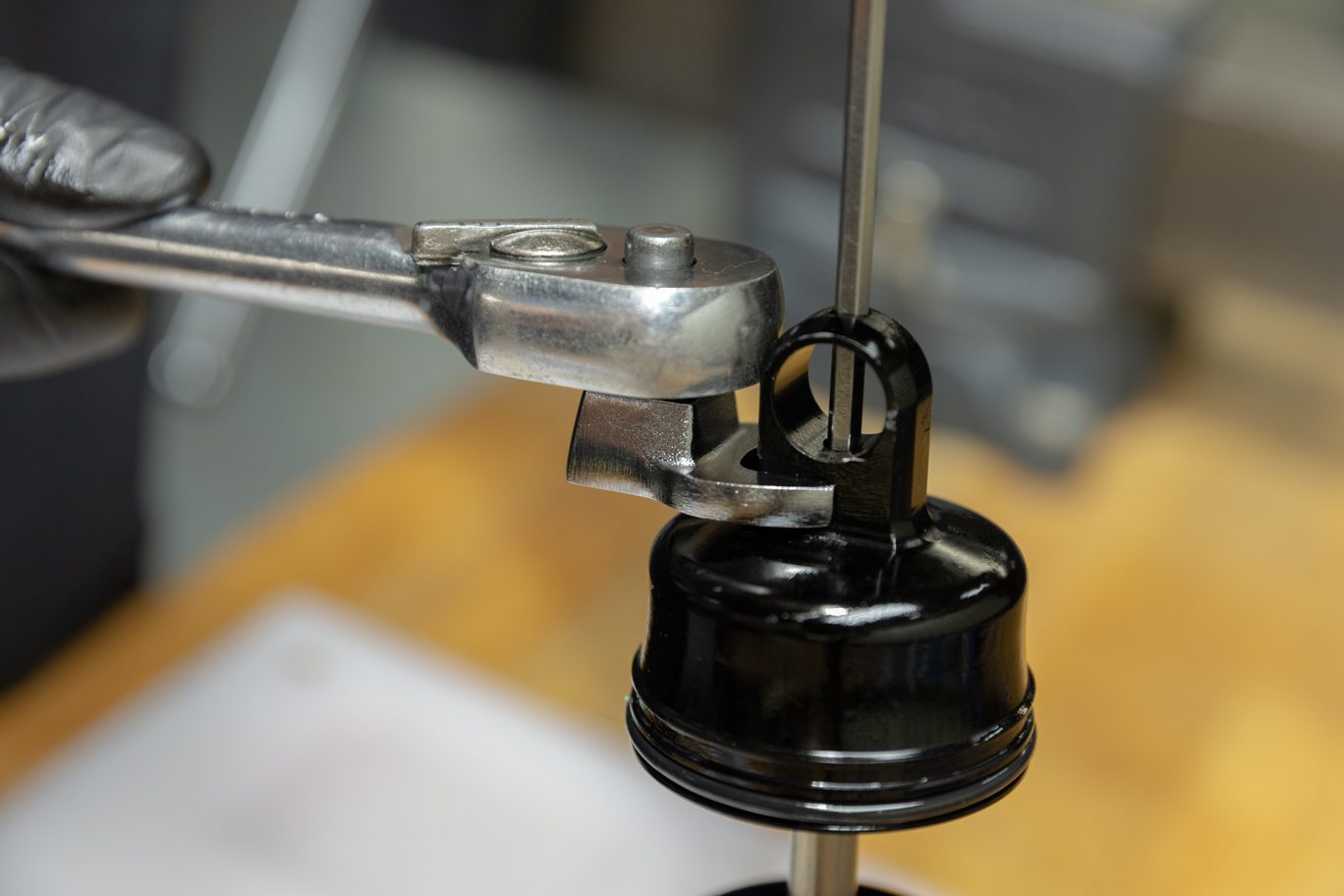
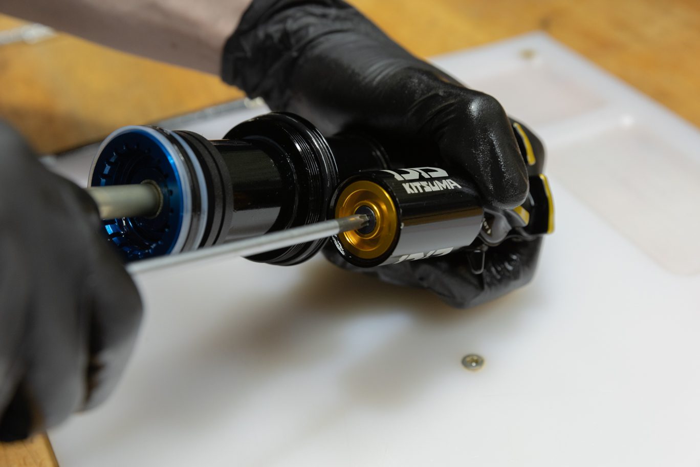
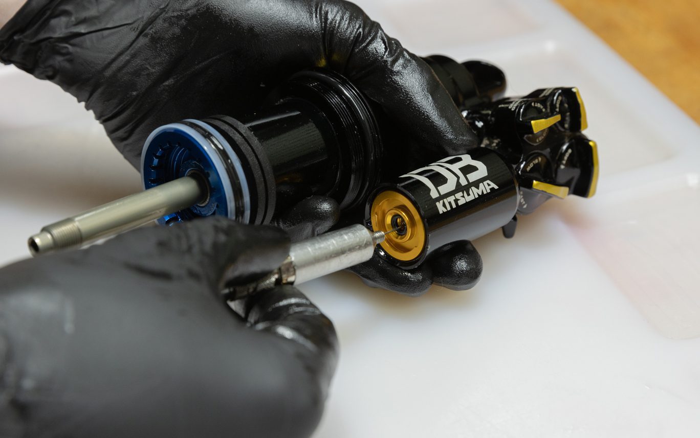
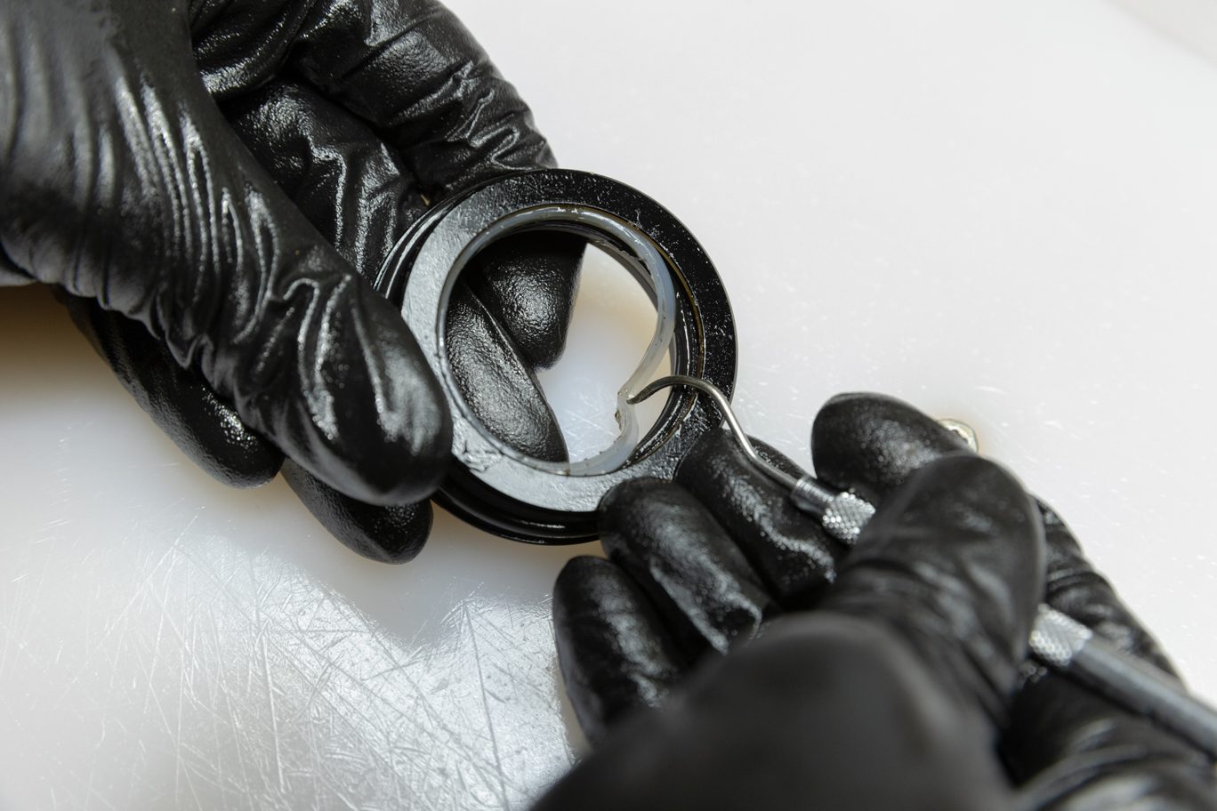
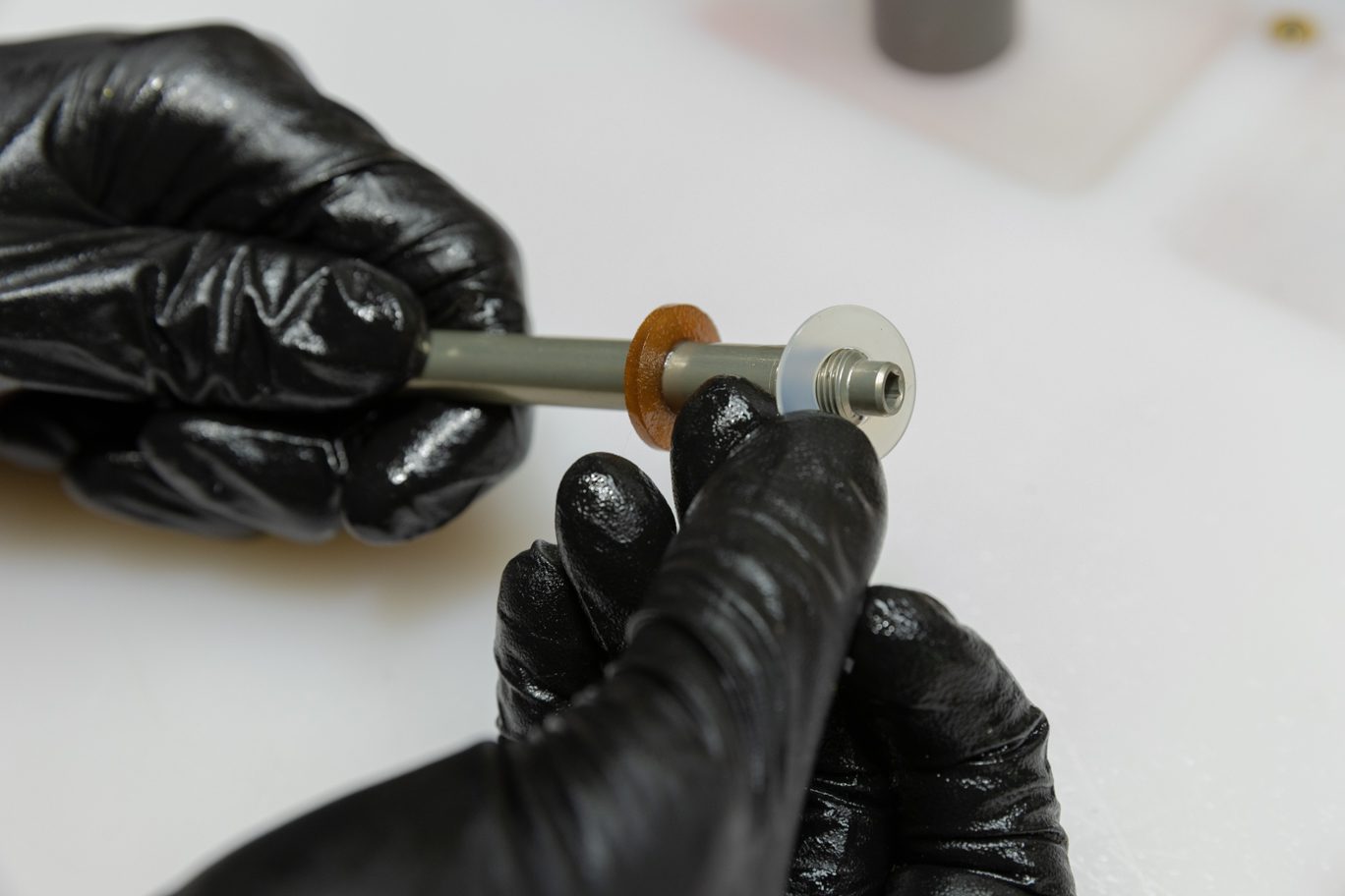
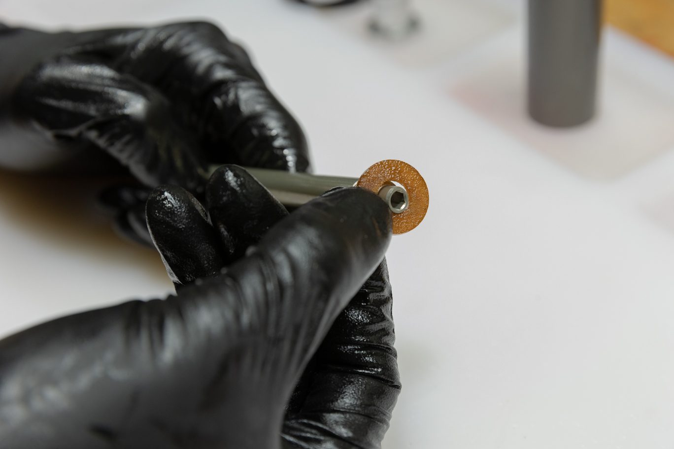
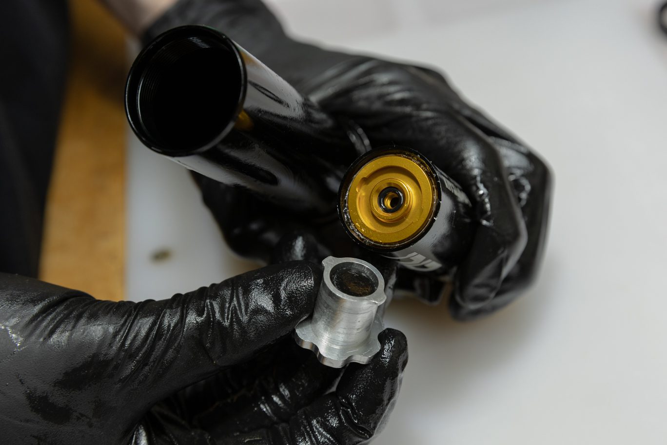
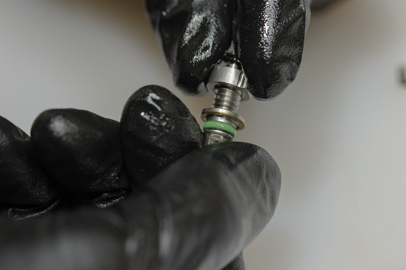
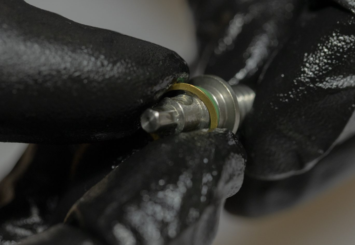
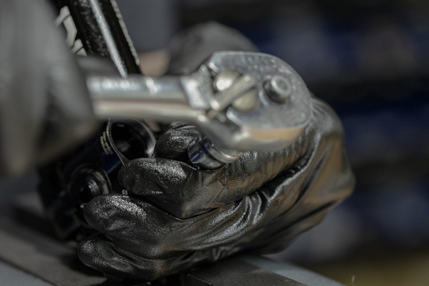
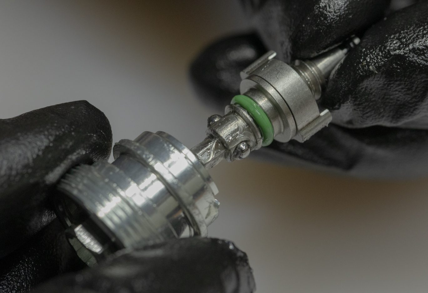
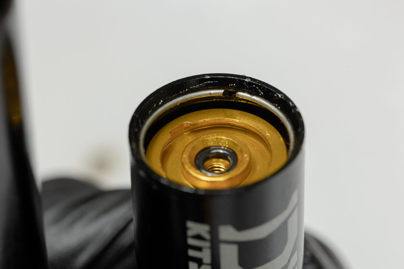
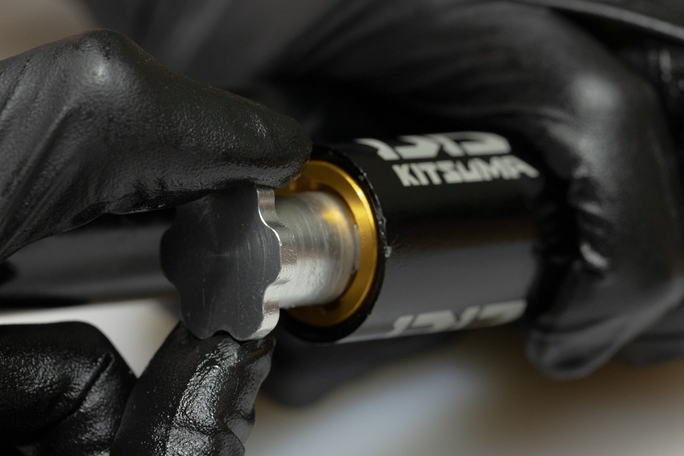
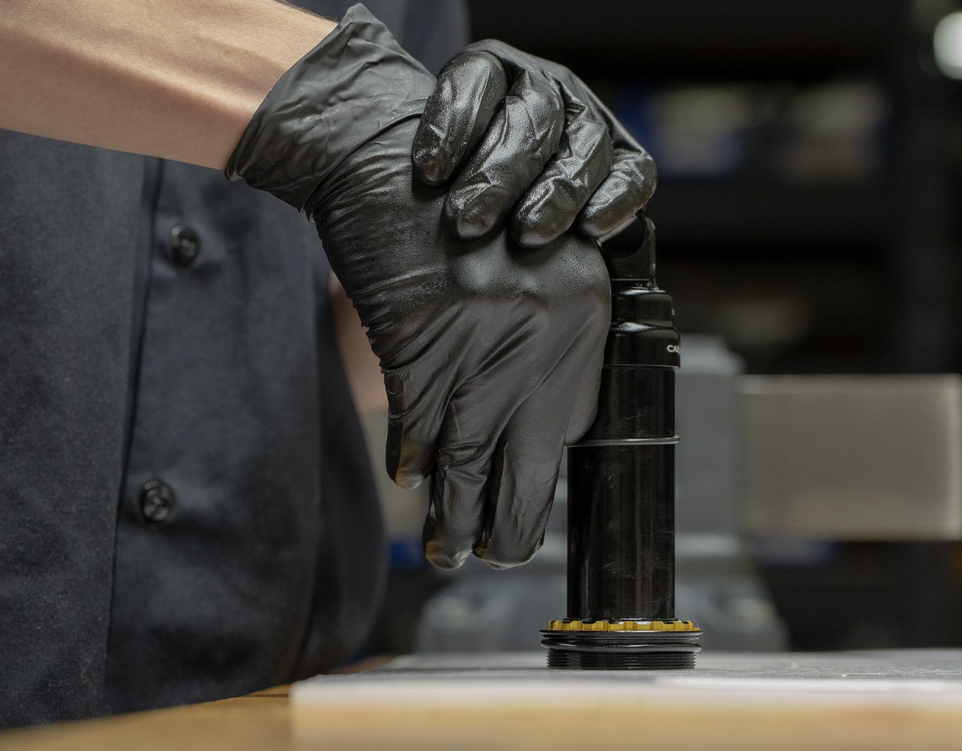
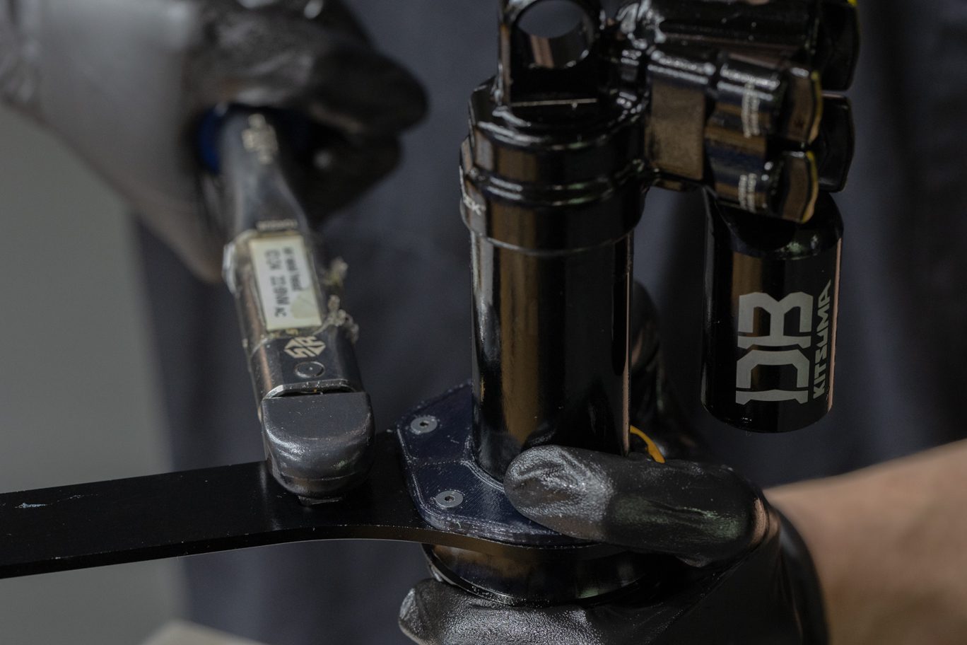
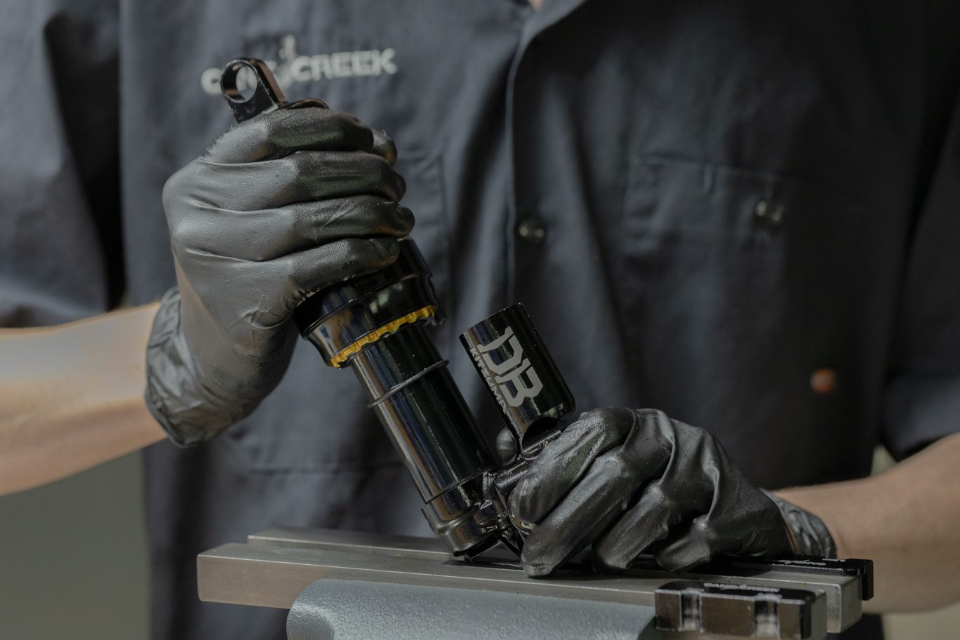
Option 1 (pictured):
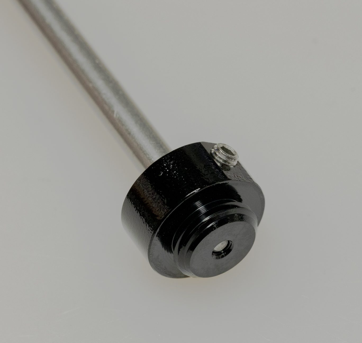
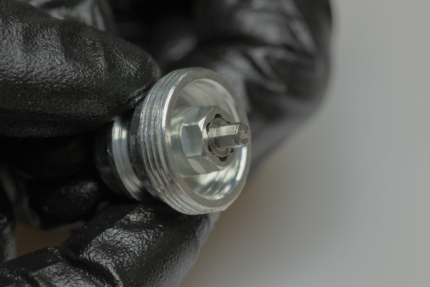
Clamping valve body, use 4mm Allen insert into end eye and 1/2″ crowsfoot, loosen end eye from shaft.
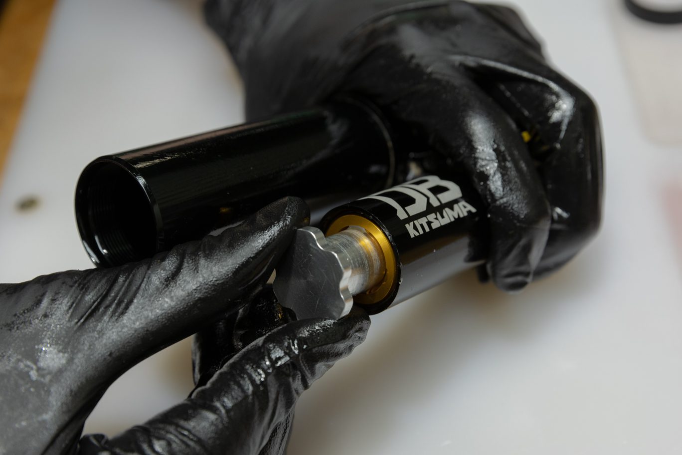
Options 2 (not pictured):
Using shaft vise, clamp shaft between end eye and air can. Use 1/2″ crowsfoot to loosen end eye from shaft.
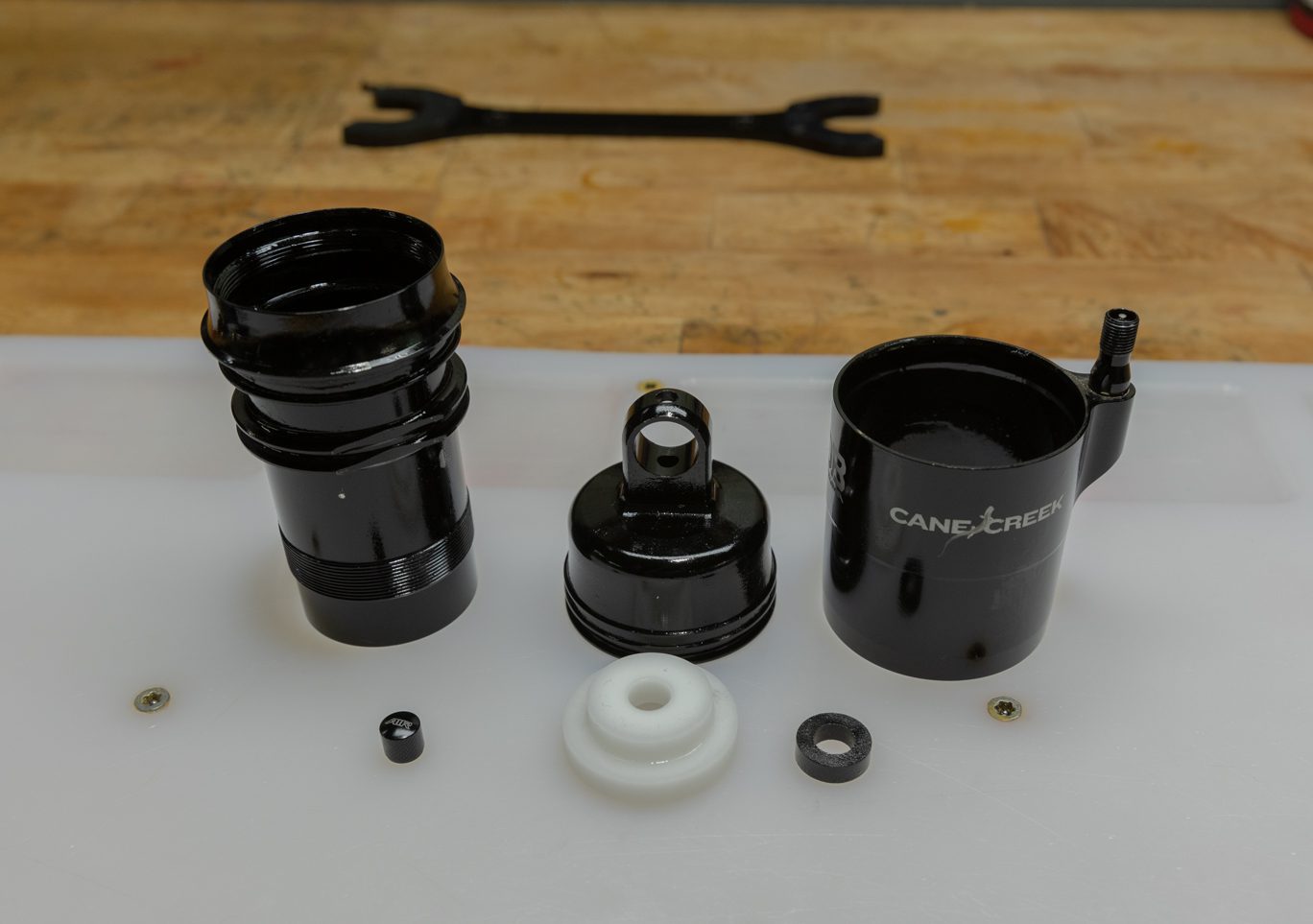
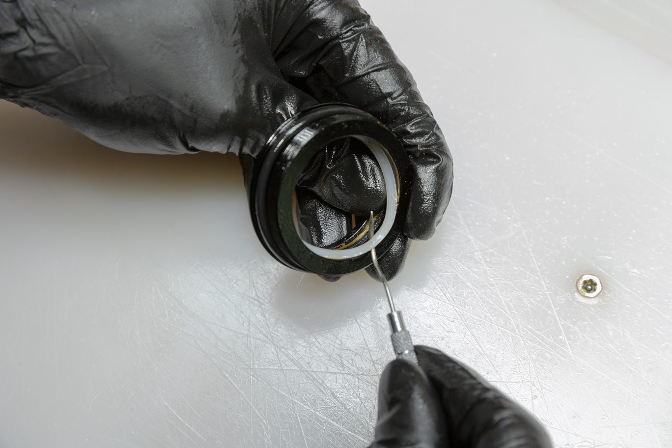
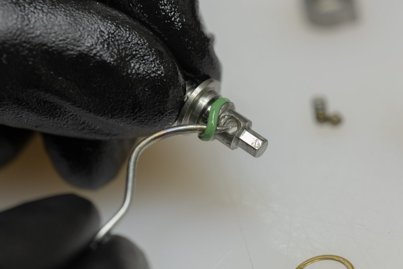
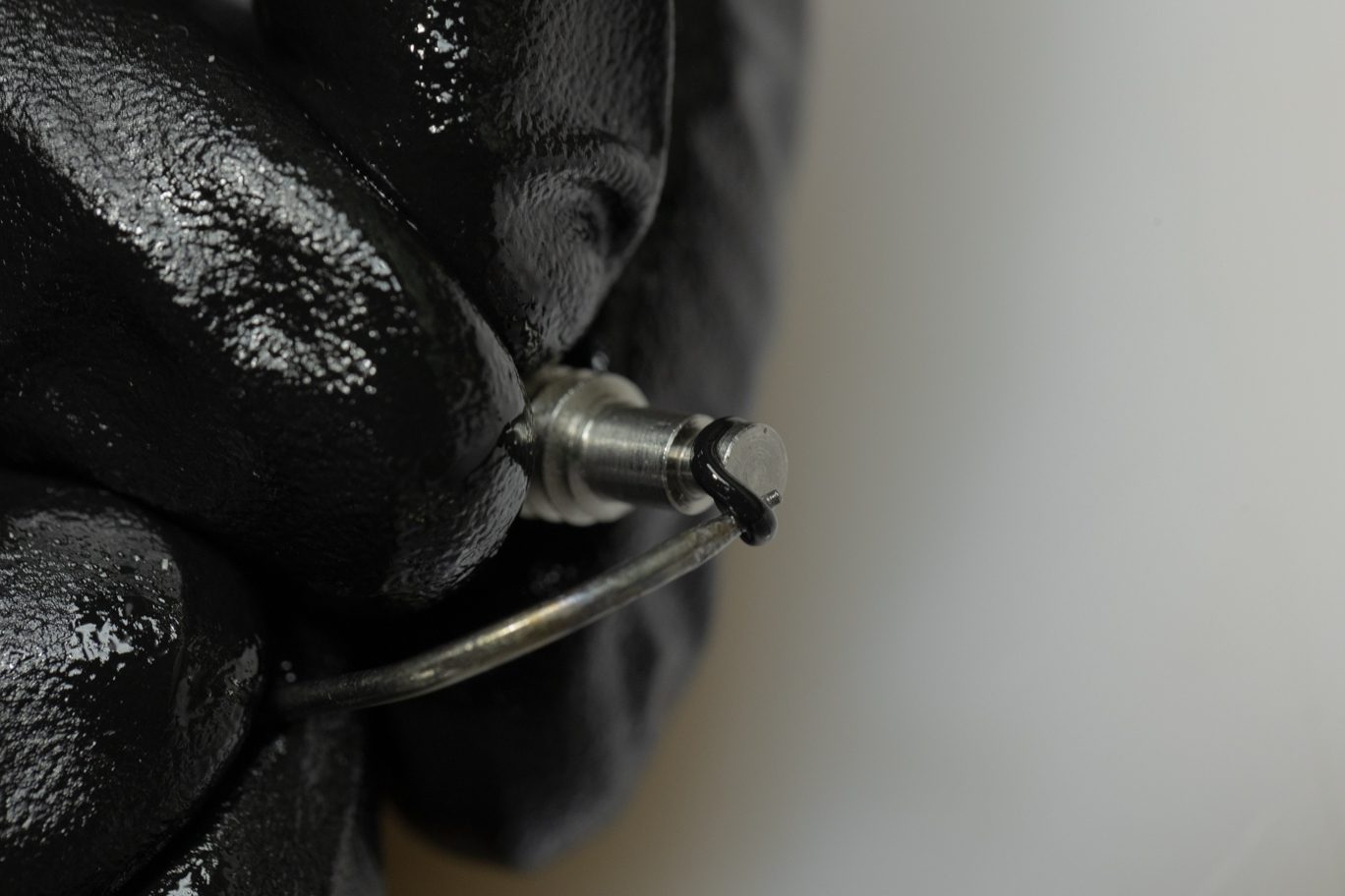
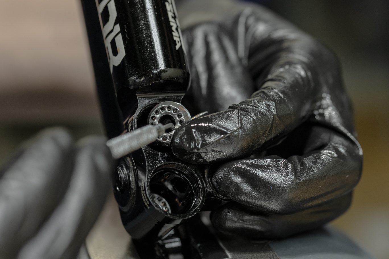
Remove and discard air can and shaft o-rings from end eye. Remove any stroke/volume reduction and bottom out bumper.
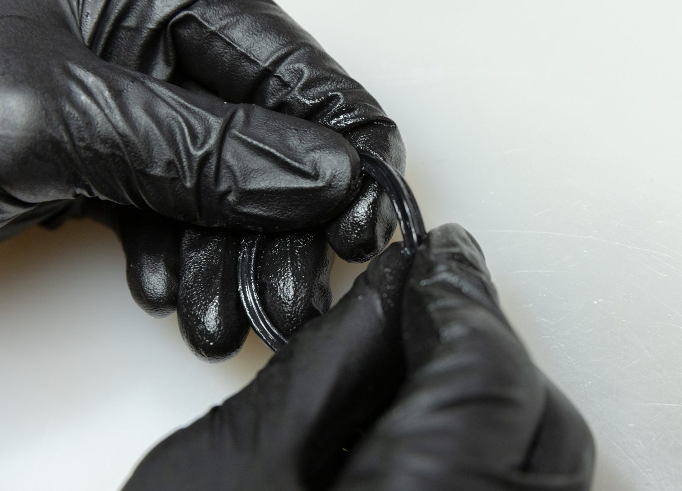
Always use extreme caution when using a pick in this step or others to avoid scratching metal parts. Failure to do this can create scratches in the o-ring glands which cause leak paths for oil or gas. When possible, pinch and remove o-rings rather than using a pick.
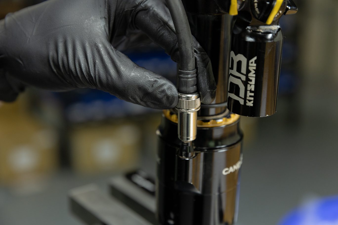
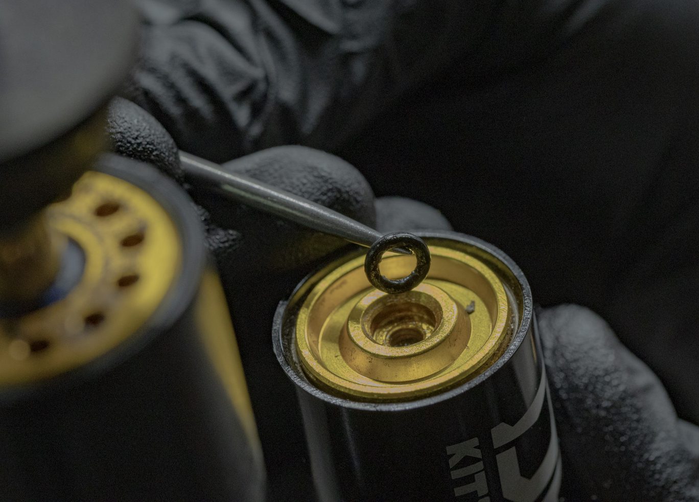
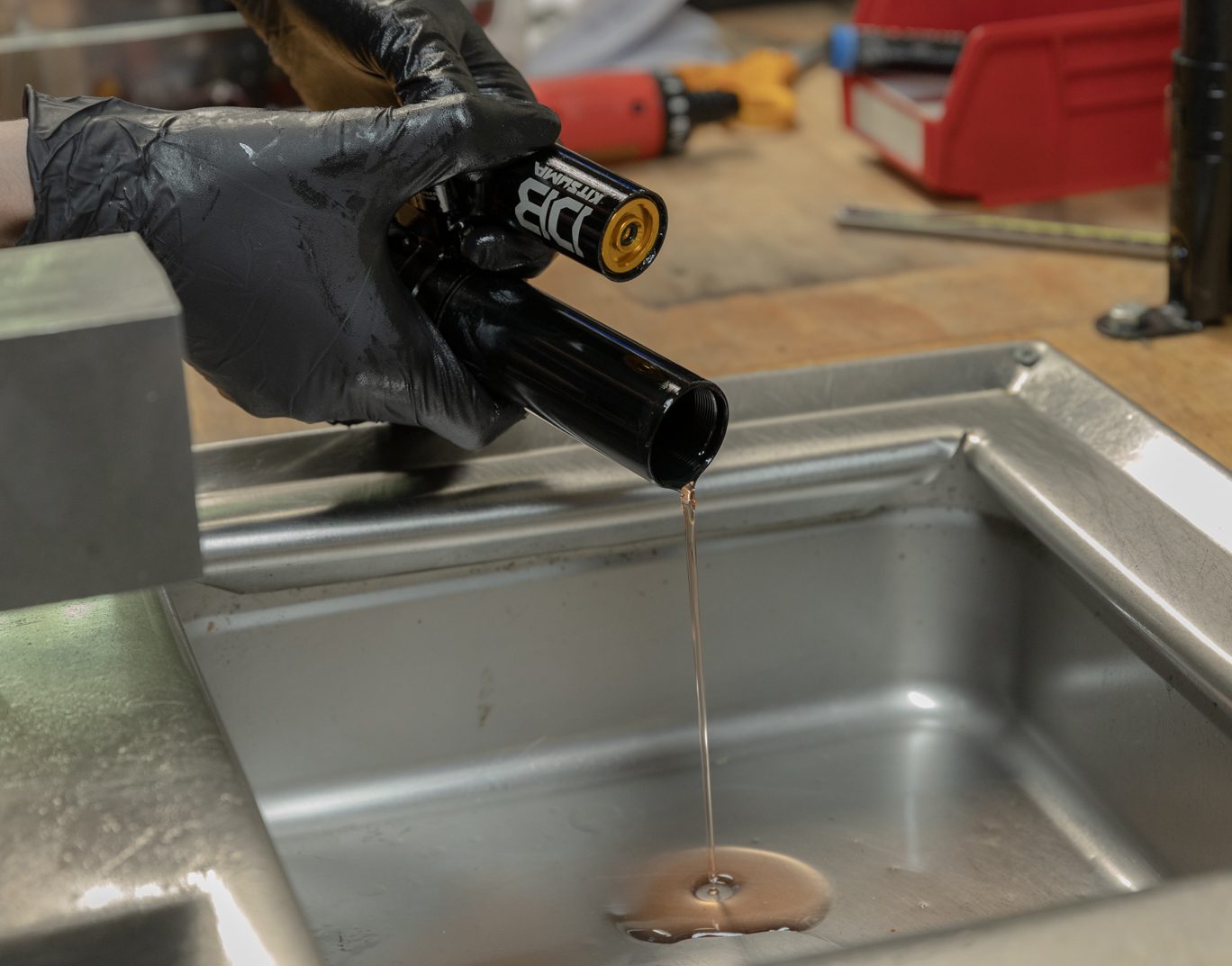
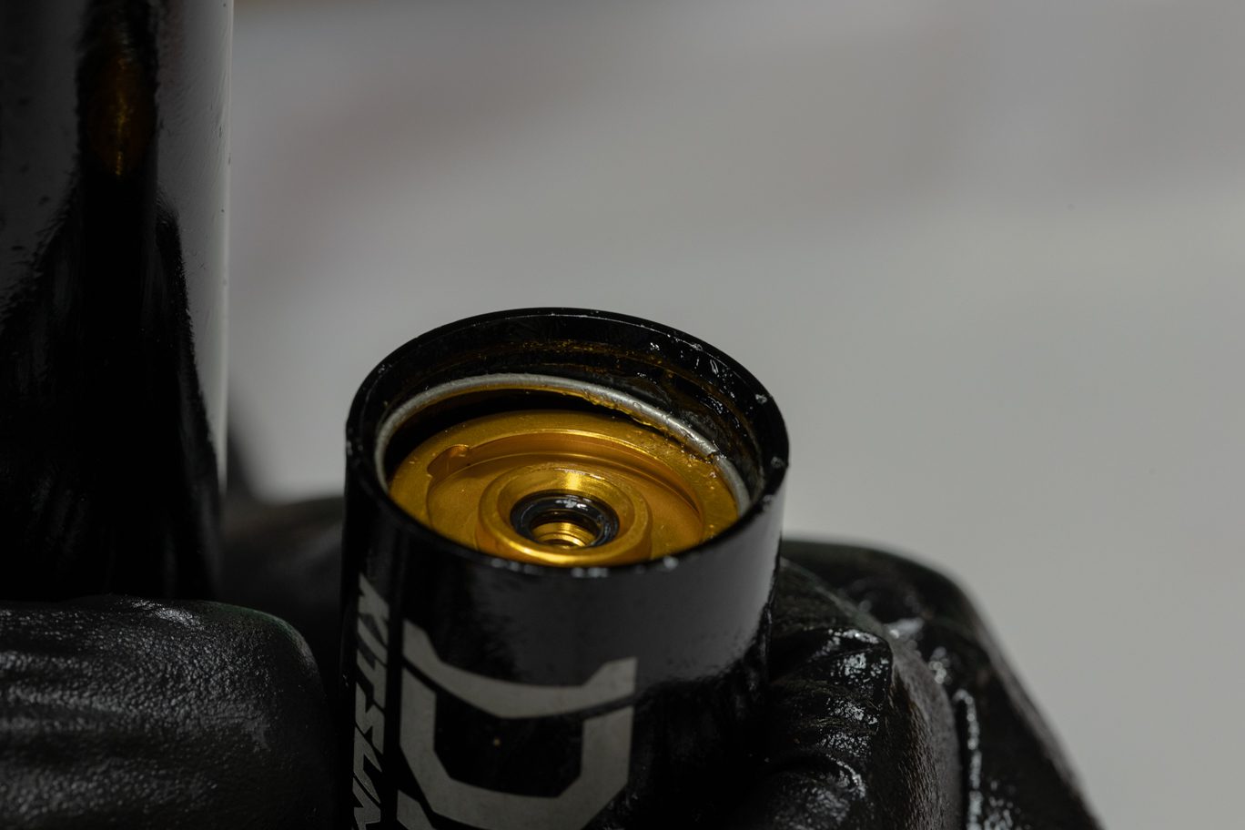
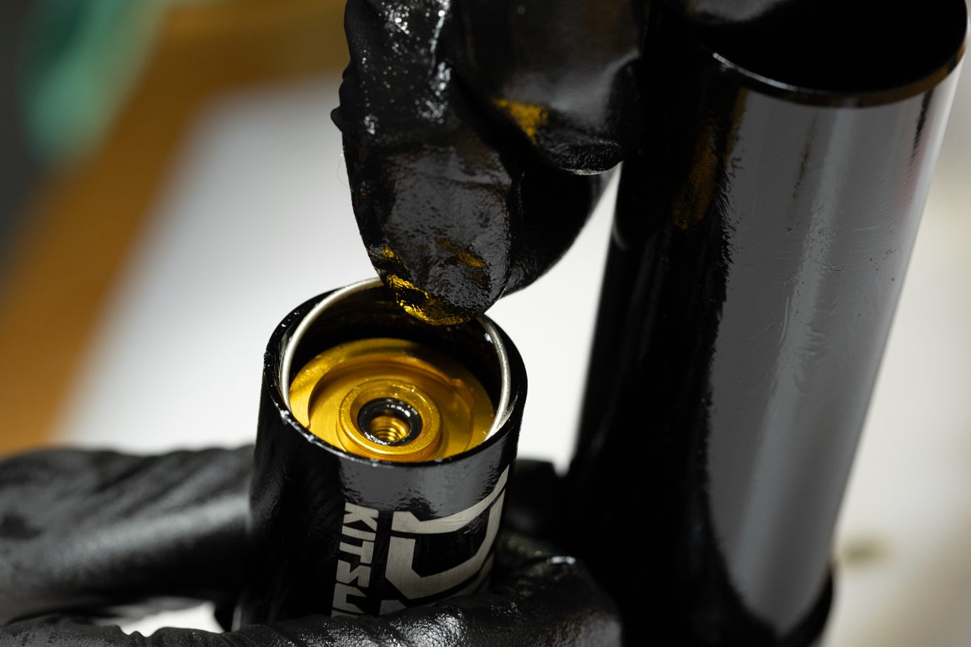
***Use caution as nitrogen is pressurized.***
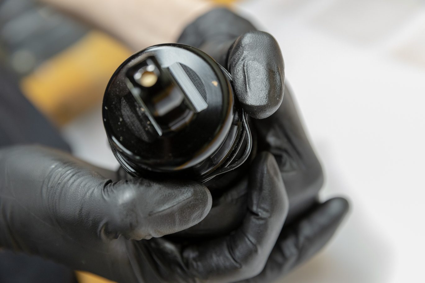
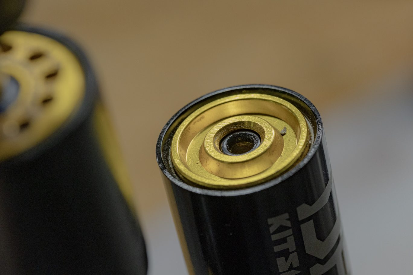
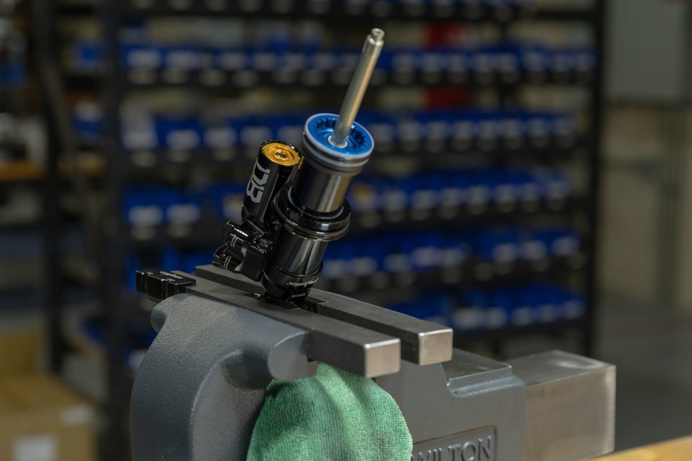
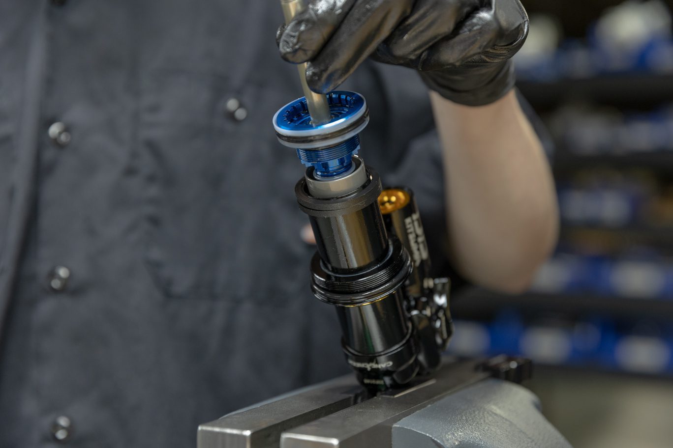
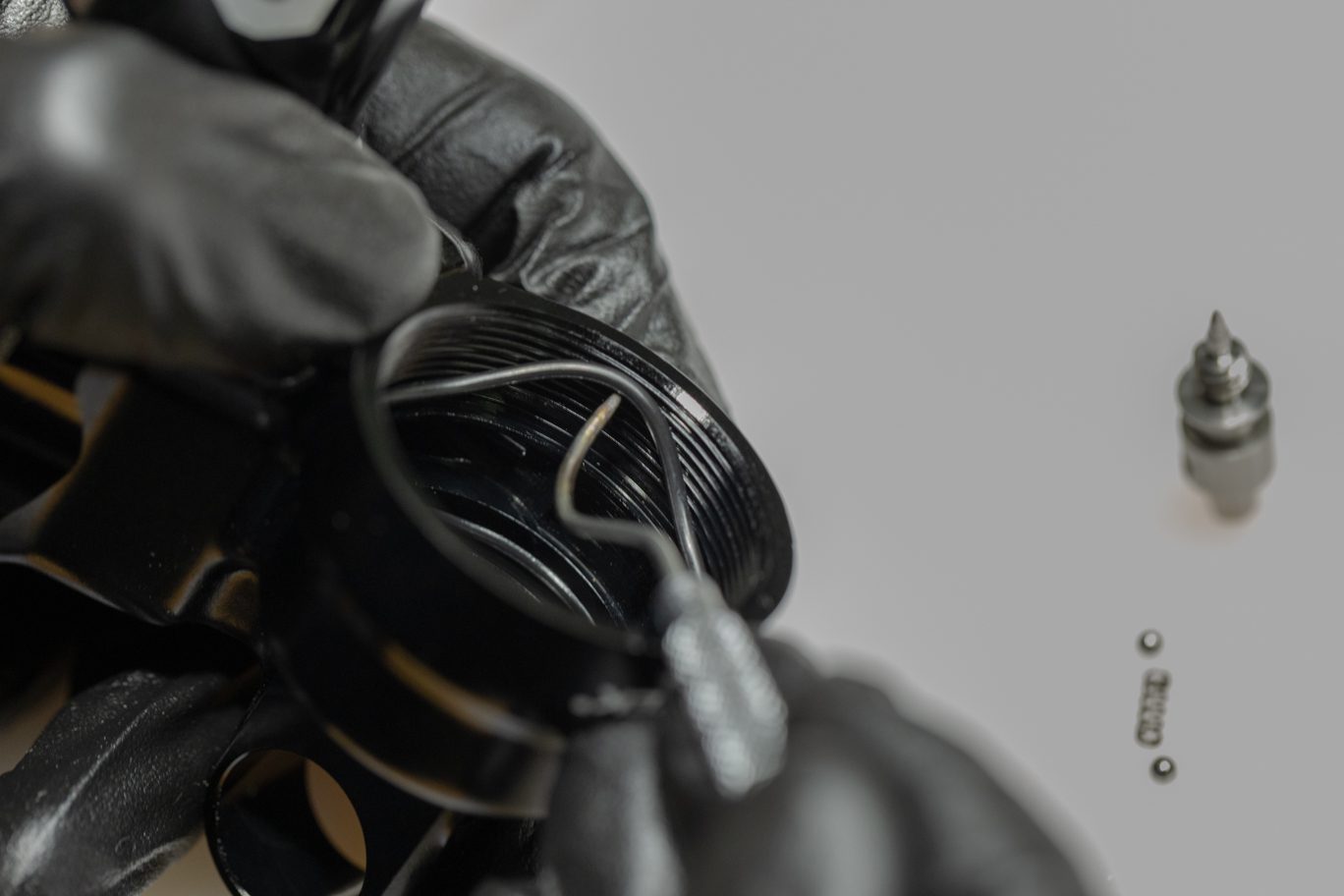
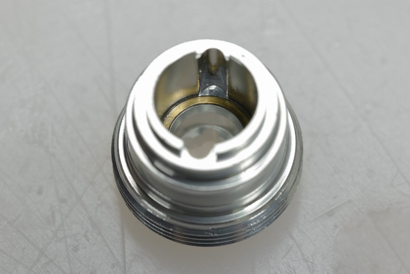
Remove reservoir end cap screw using T20. Remove and discard o-ring. Use gas fill needle to bleed nitrogen from reservoir tube. Temporarily reinstall end eye on shaft. Remove oil fill screw with T20. Cycle the shaft to remove as much oil as possible from the damper. Dispose of oil properly. Remove end eye.
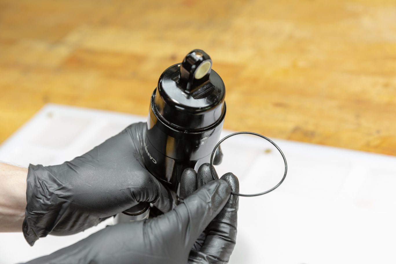
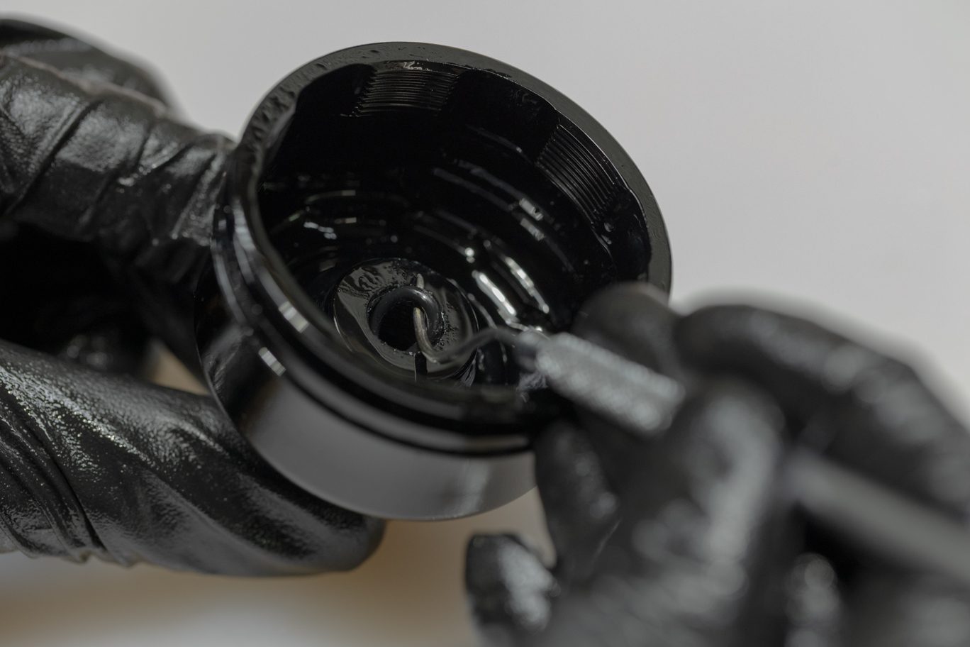
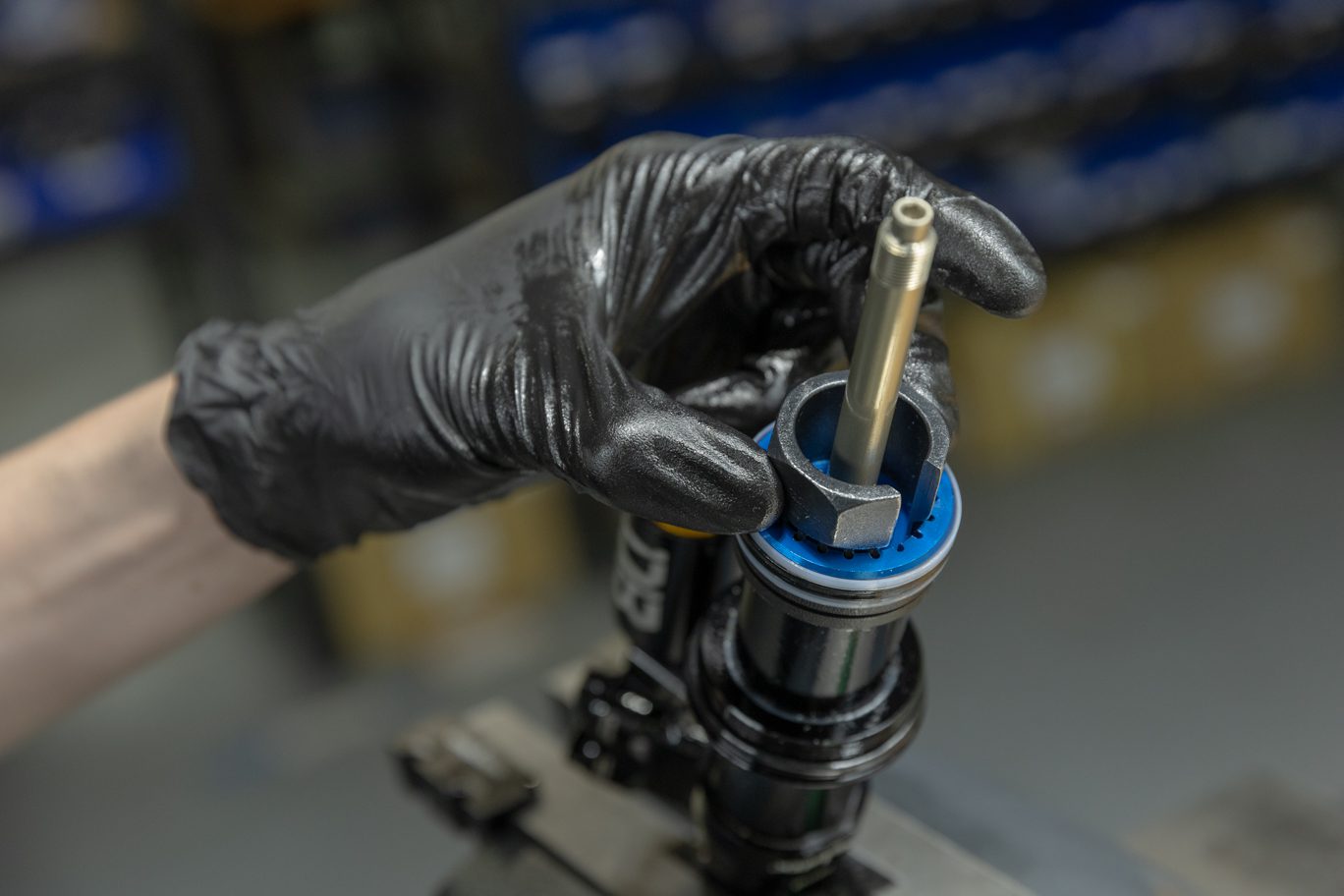
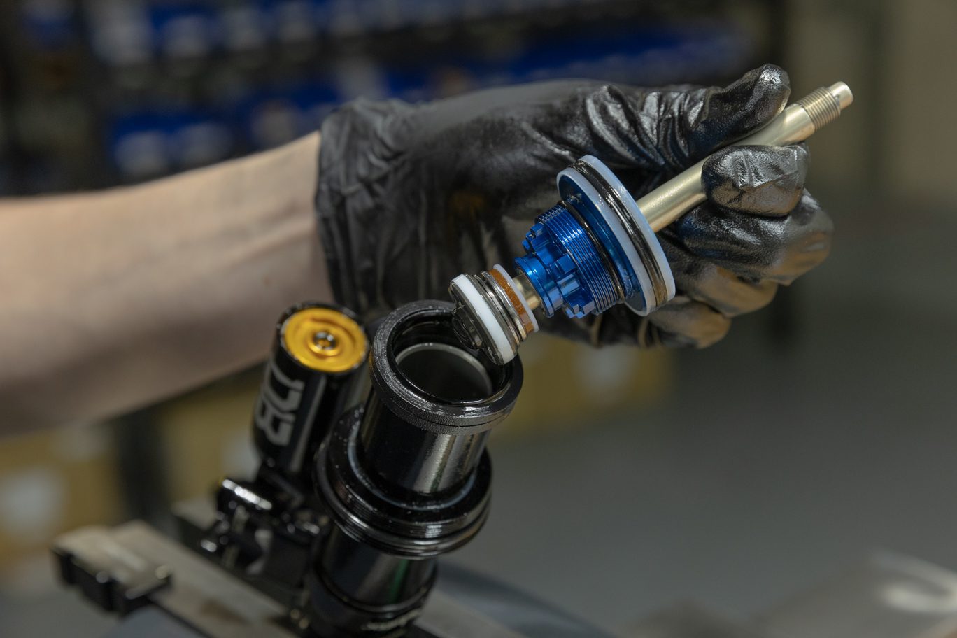
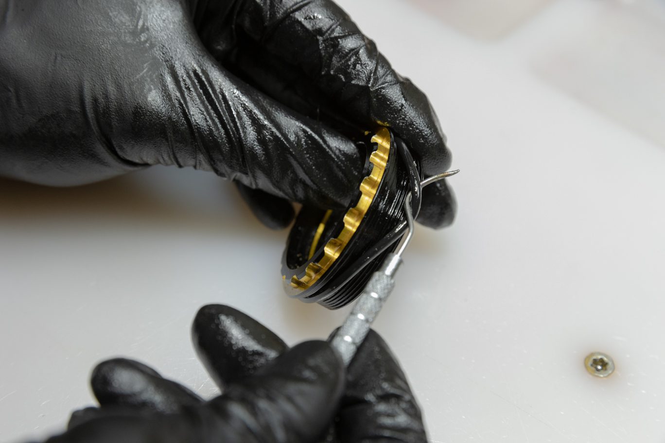
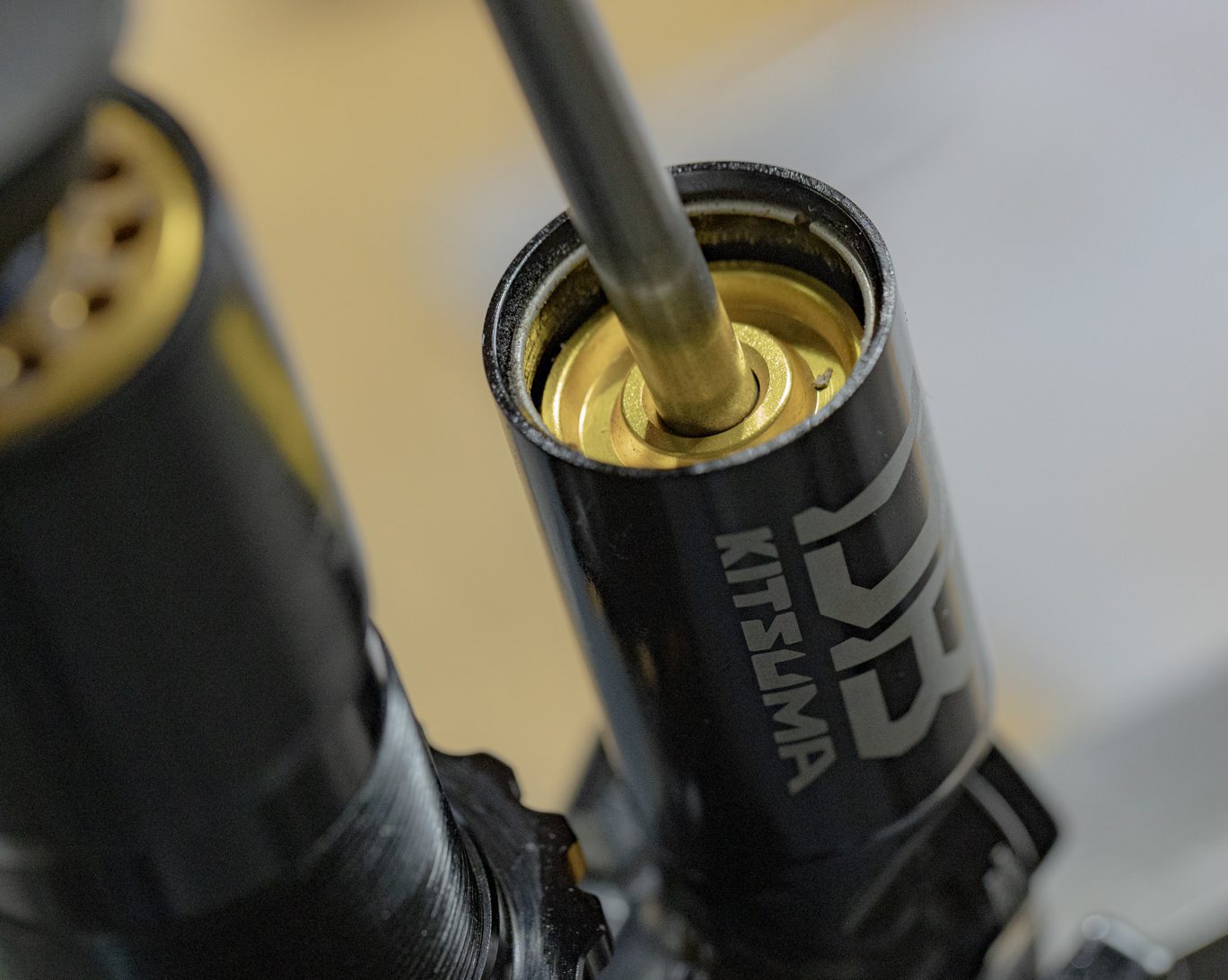
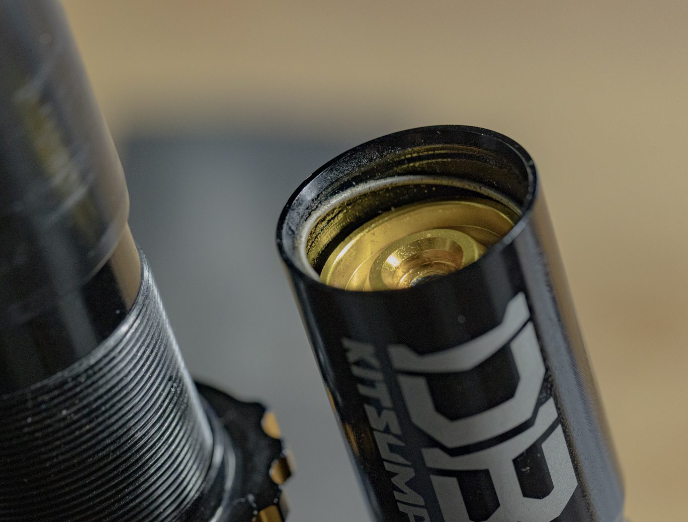
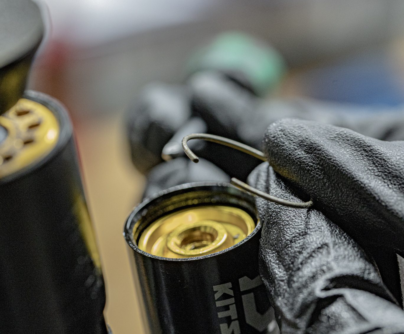
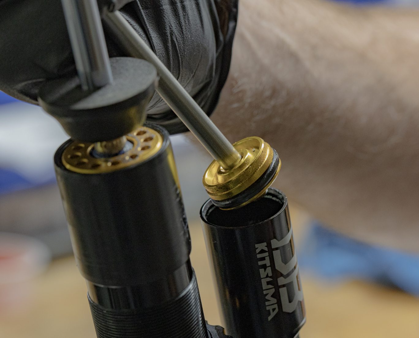
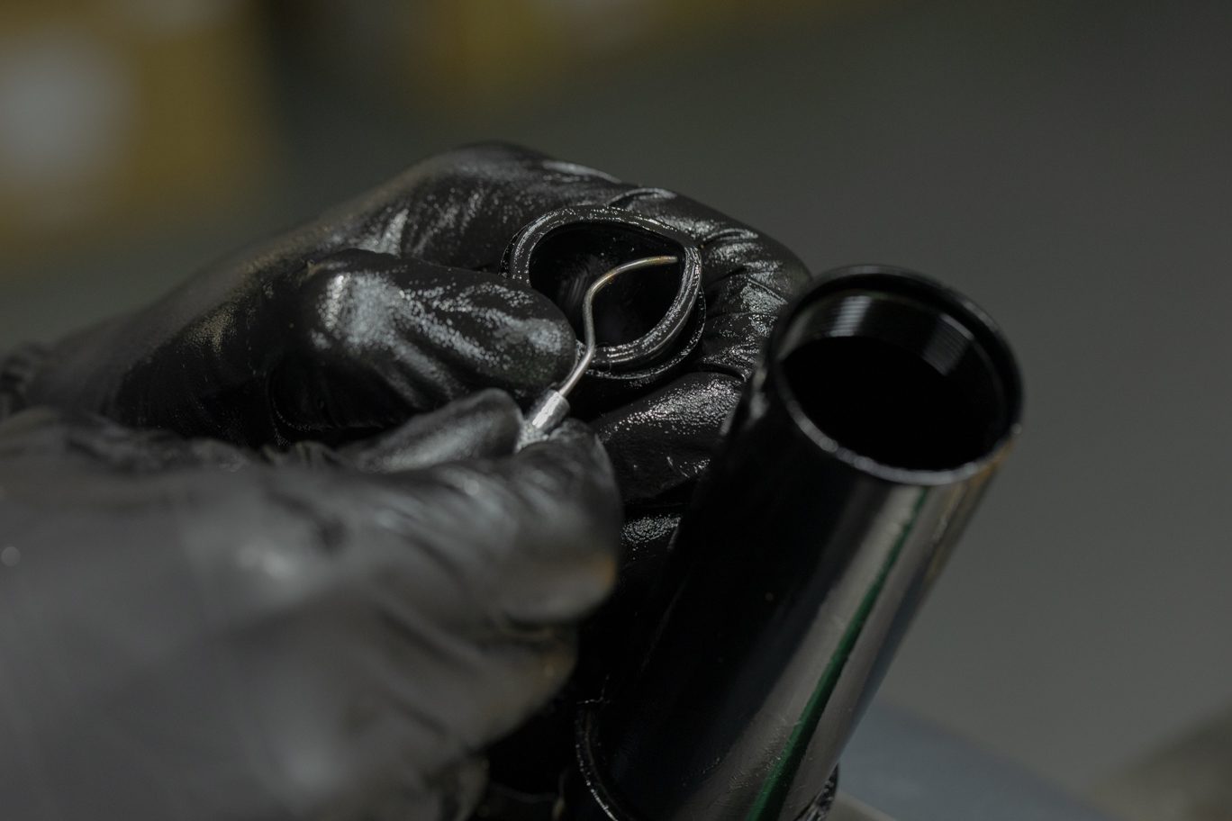
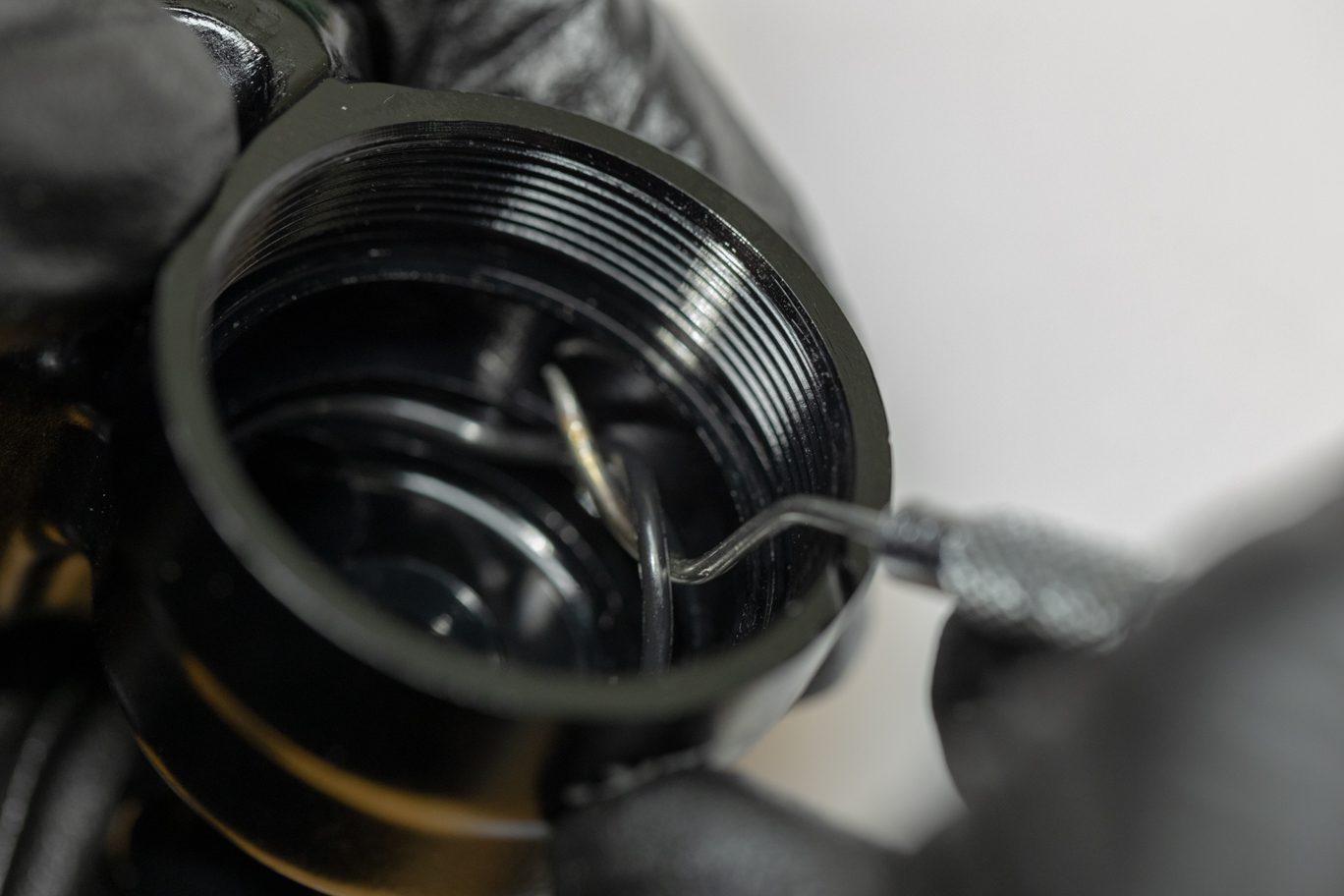
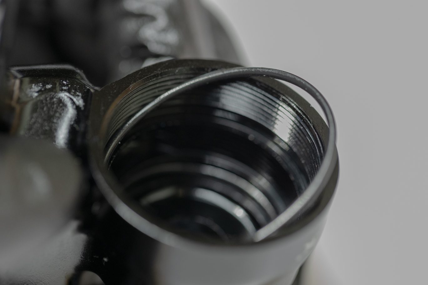
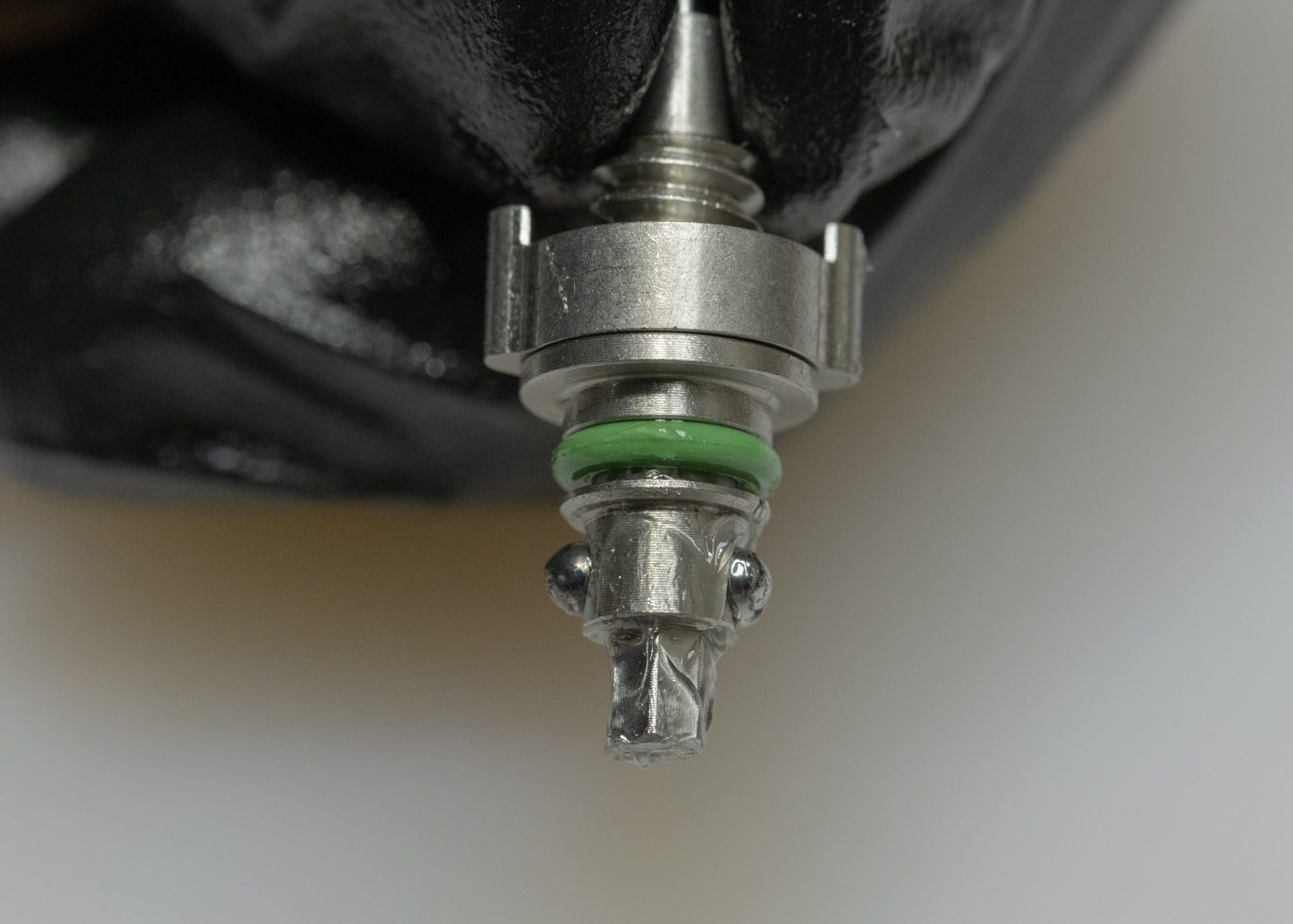
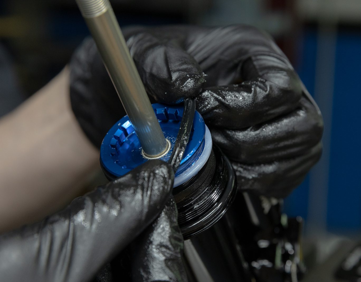
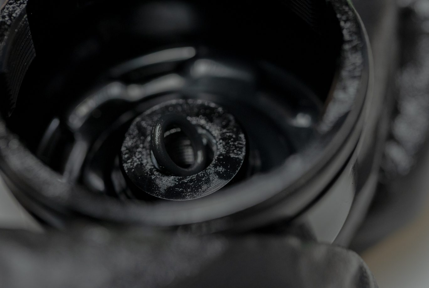
Using IFP tool (DBT012), press cap into the reservoir tube exposing circlip. Press on circlip to remove from channel. Pick should not be required but could be used if needed. Thread IFP tool back into end cap, remove and discard. Thread IFP tool into metal IFP and remove from reservoir tube. Use adaptor for plastic IFP. Discard IFP.
TSB045 – Kitsuma IFP Changed to Bladder
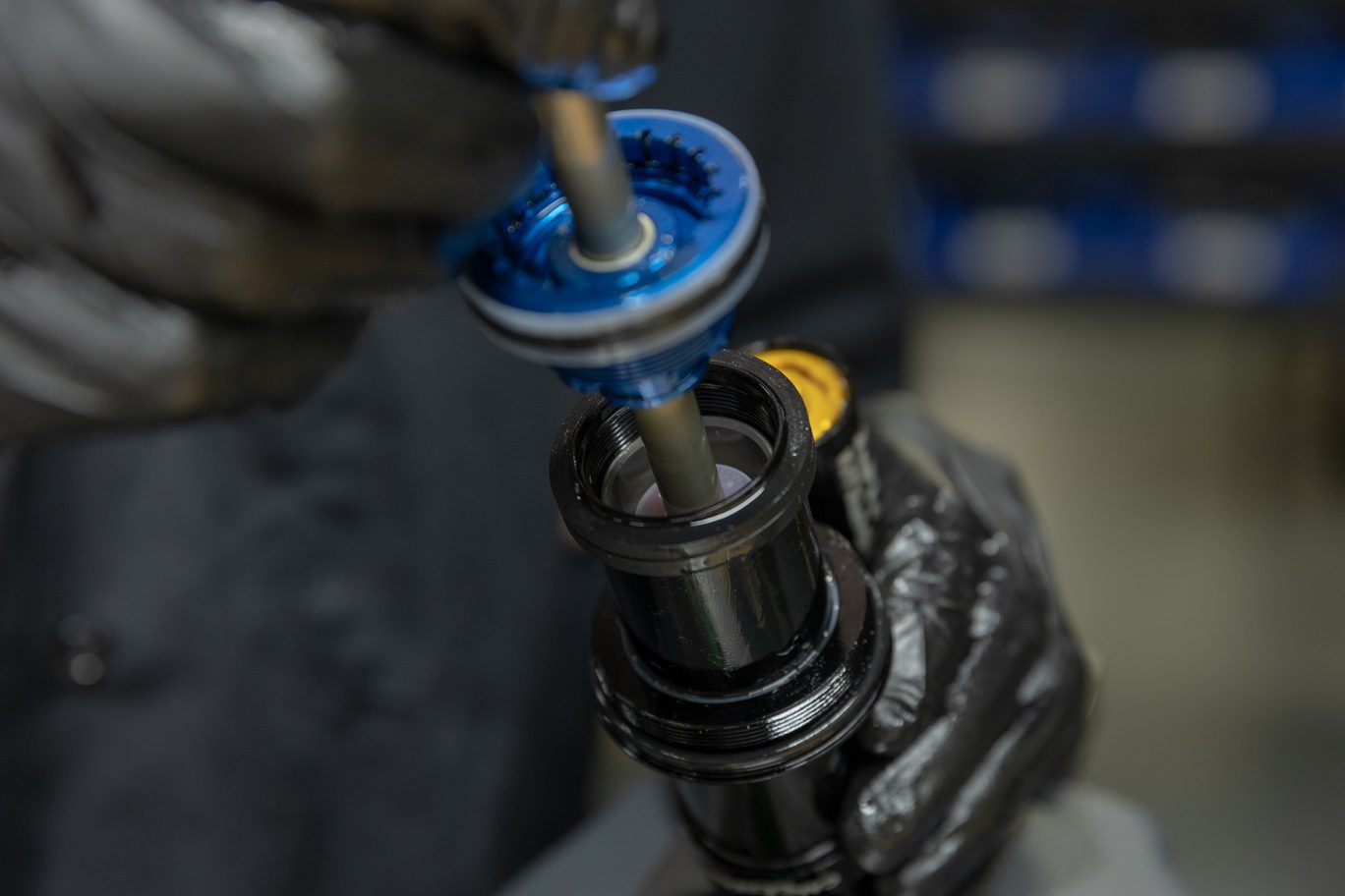
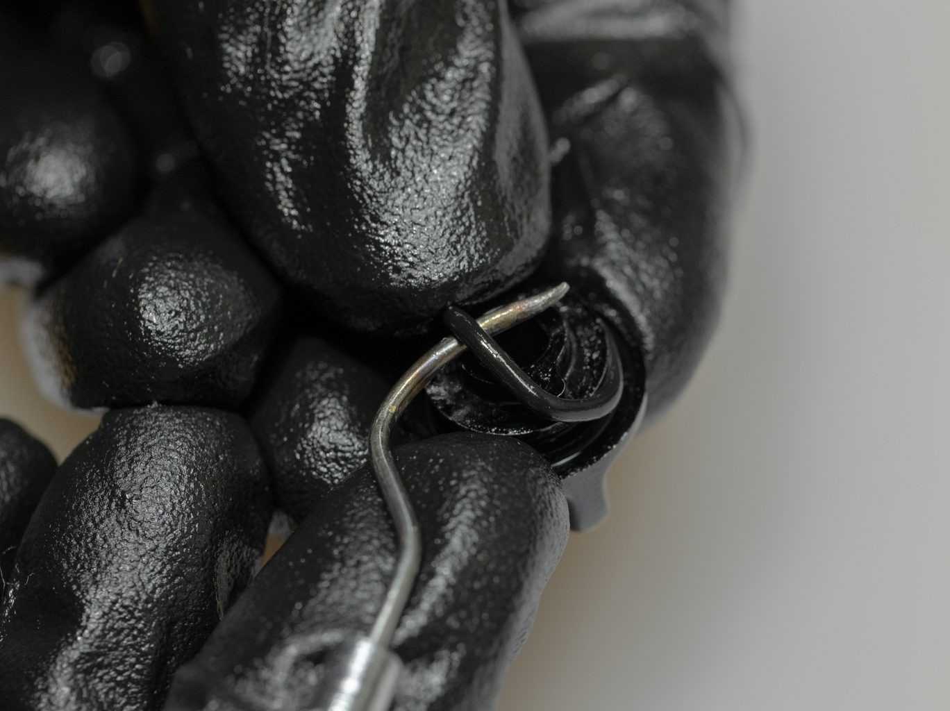
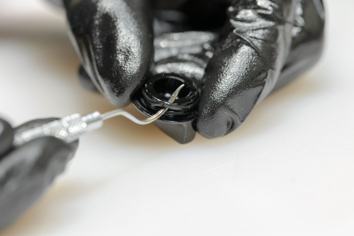
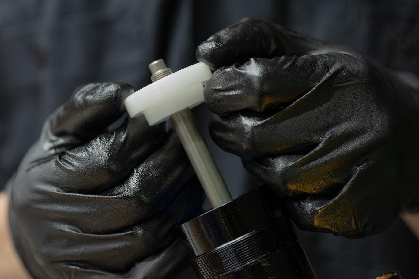
Using bladder setting tool (ACD0354), press res end cap into reservoir, exposing circlip. Press on circlip to remove from channel. Pick should not be required but could be used if needed. Use IFP setting tool (DBT012) to pull end cap out of reservoir tube. If bladder does not come out with end cap, remove with pick.
TSB045 – Kitsuma IFP Changed to Bladder
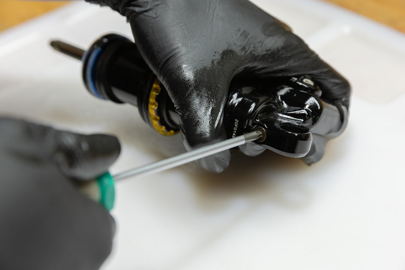
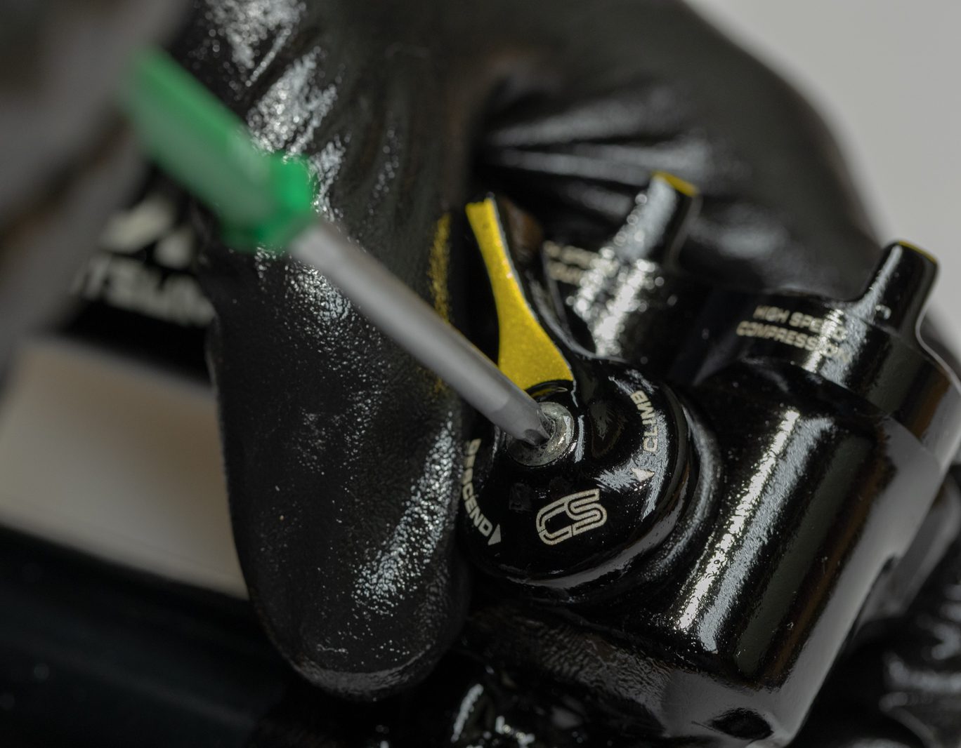
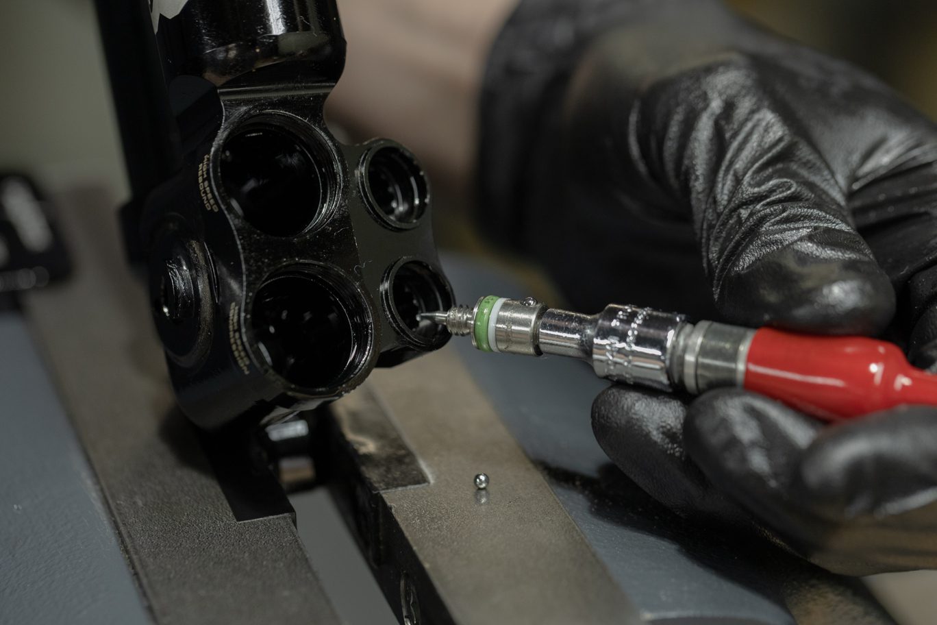
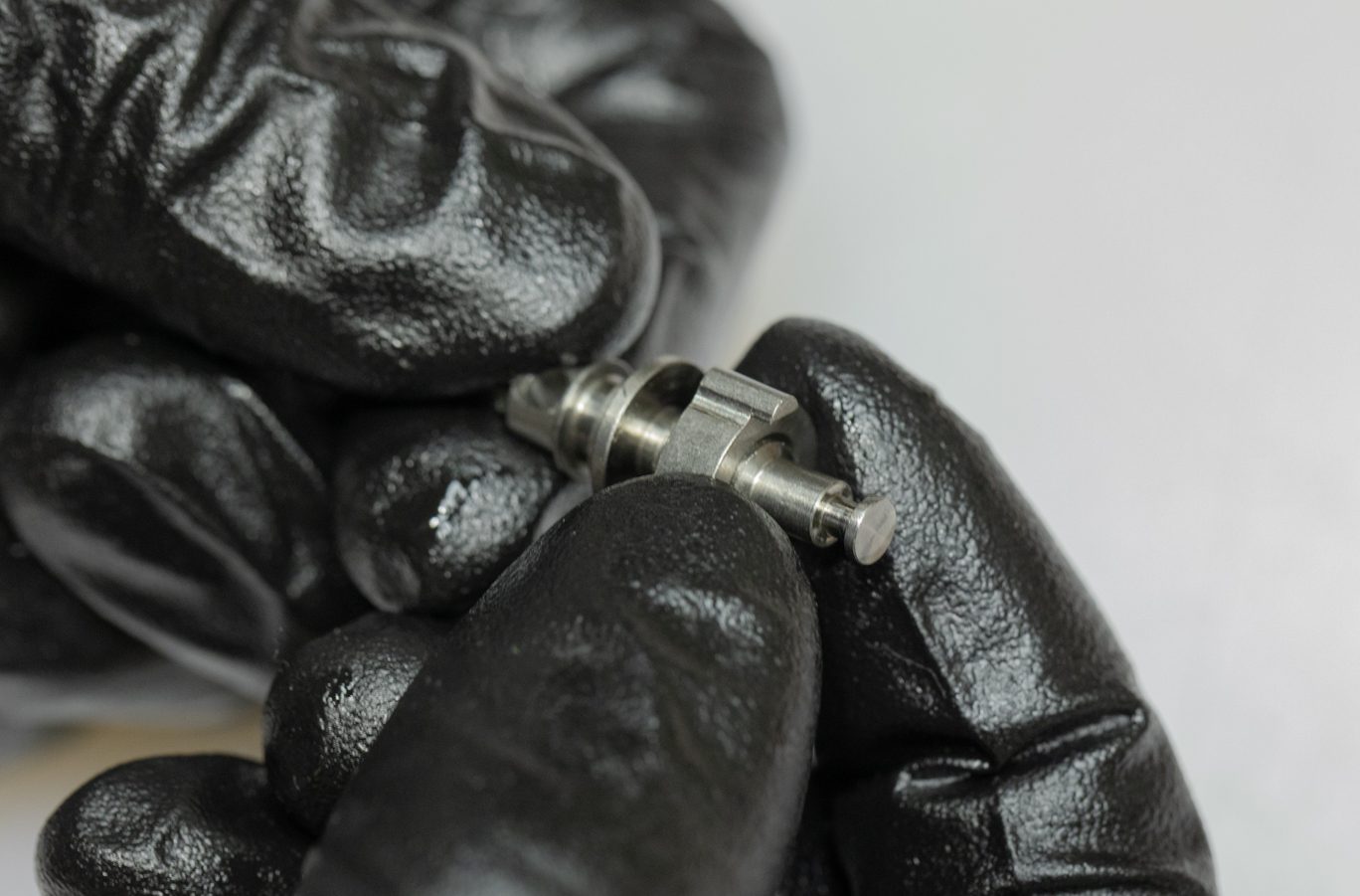
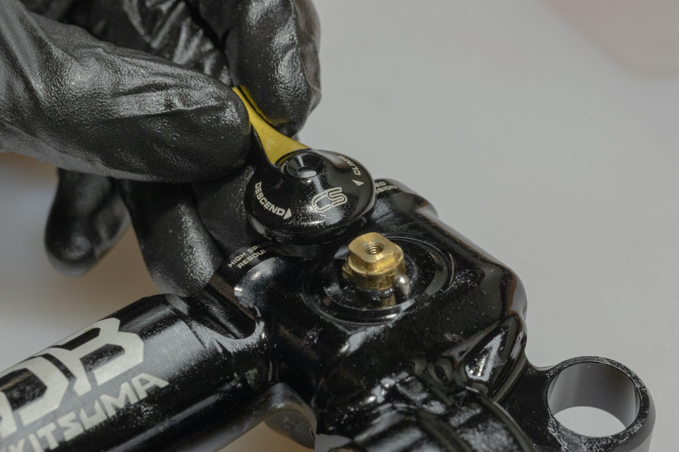
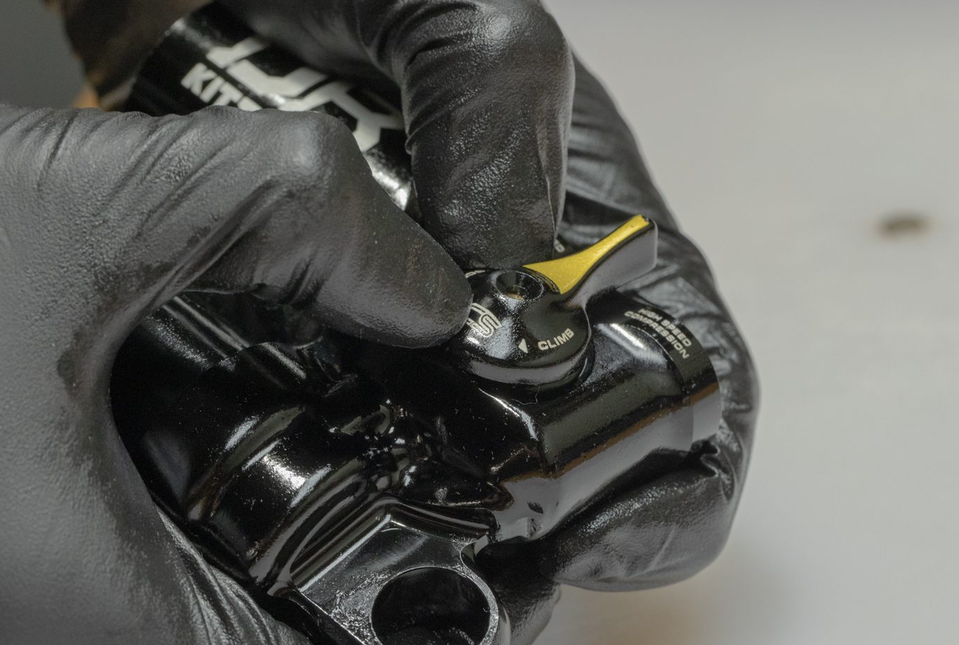
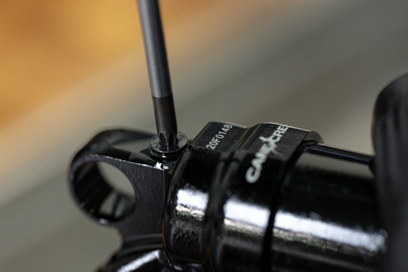
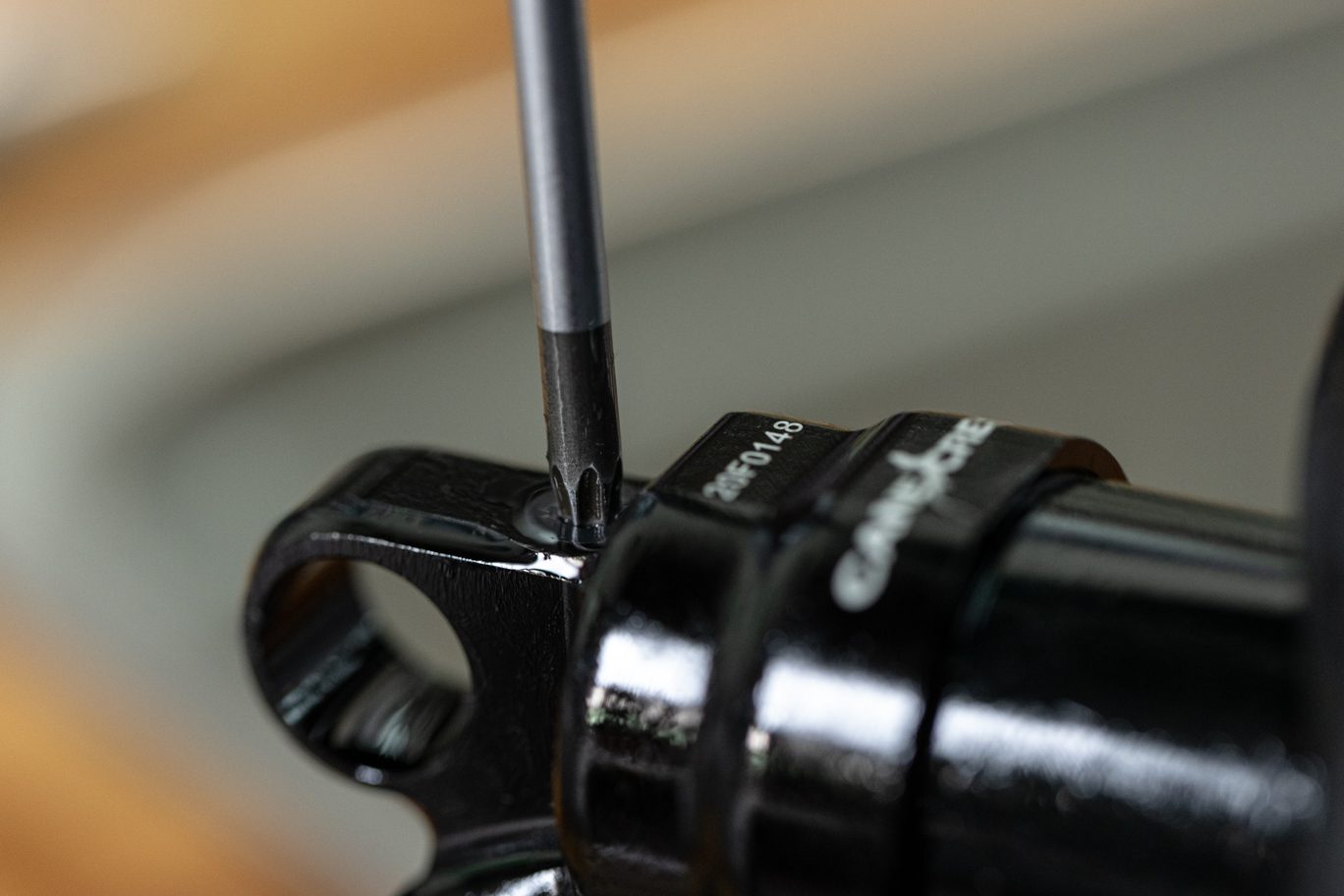
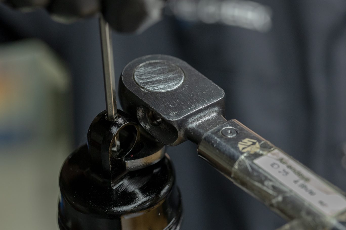
Using T10, remove Climb Switch mounting screw.
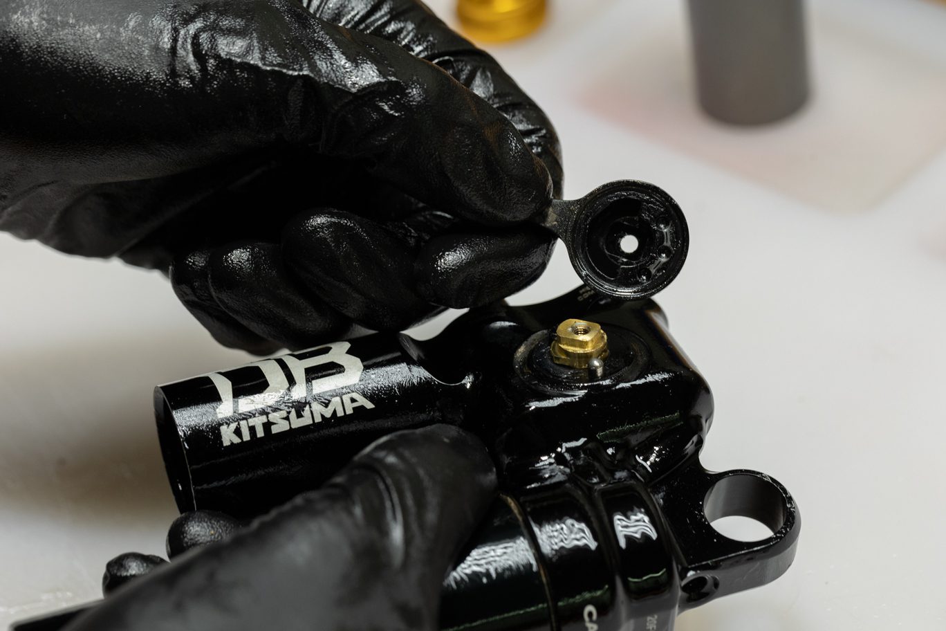
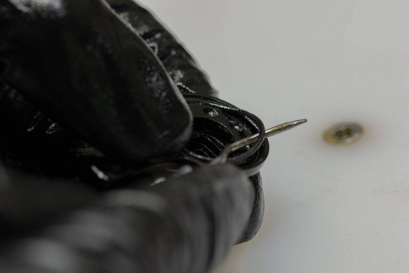
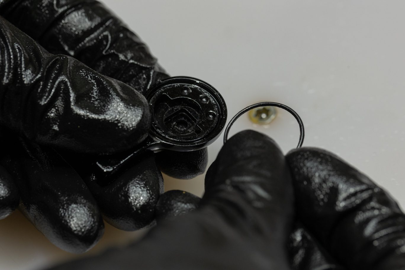
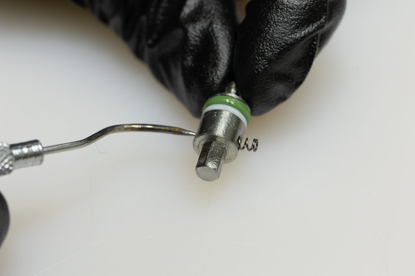
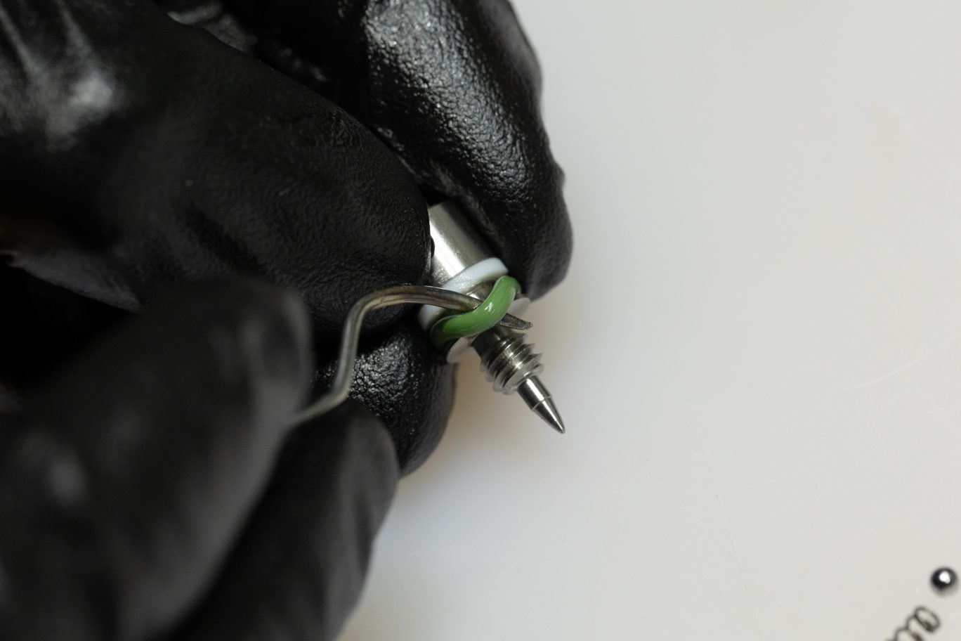
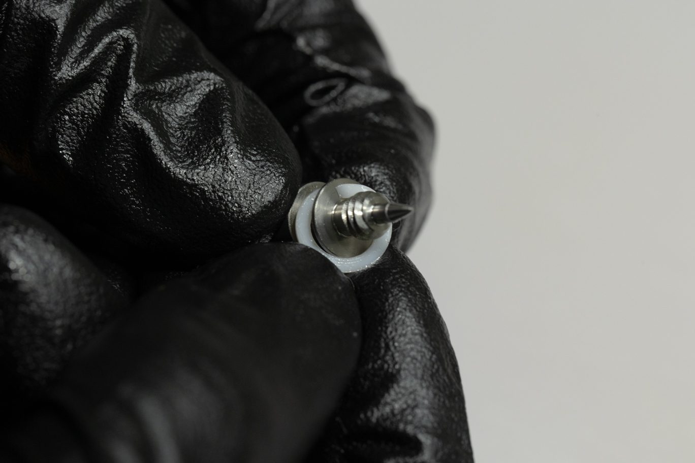
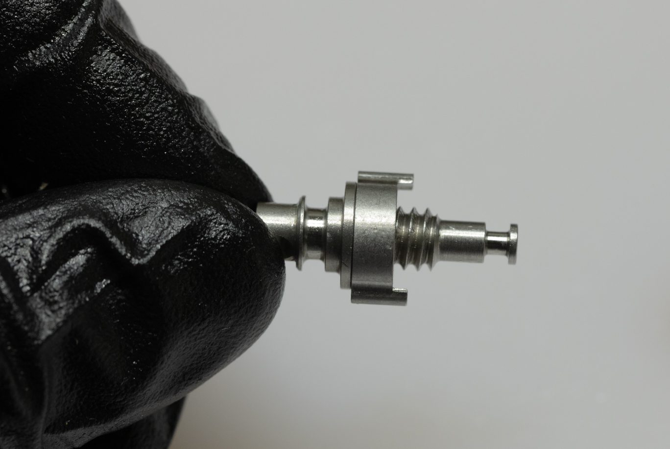
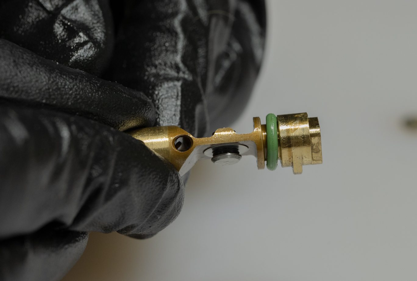
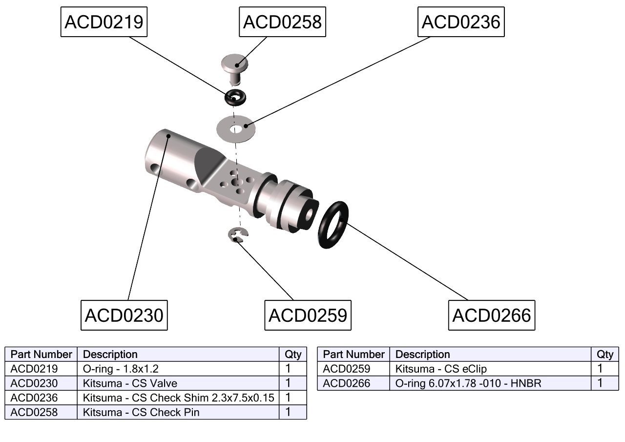
Remove Climb Switch. Remove and discard Climb Switch o-ring. Remove CS detent. Turn CS valve so that the tab on the spool valve is no longer engaged with the valve body and remove assembly. Pinch & remove and discard spool valve o-ring.
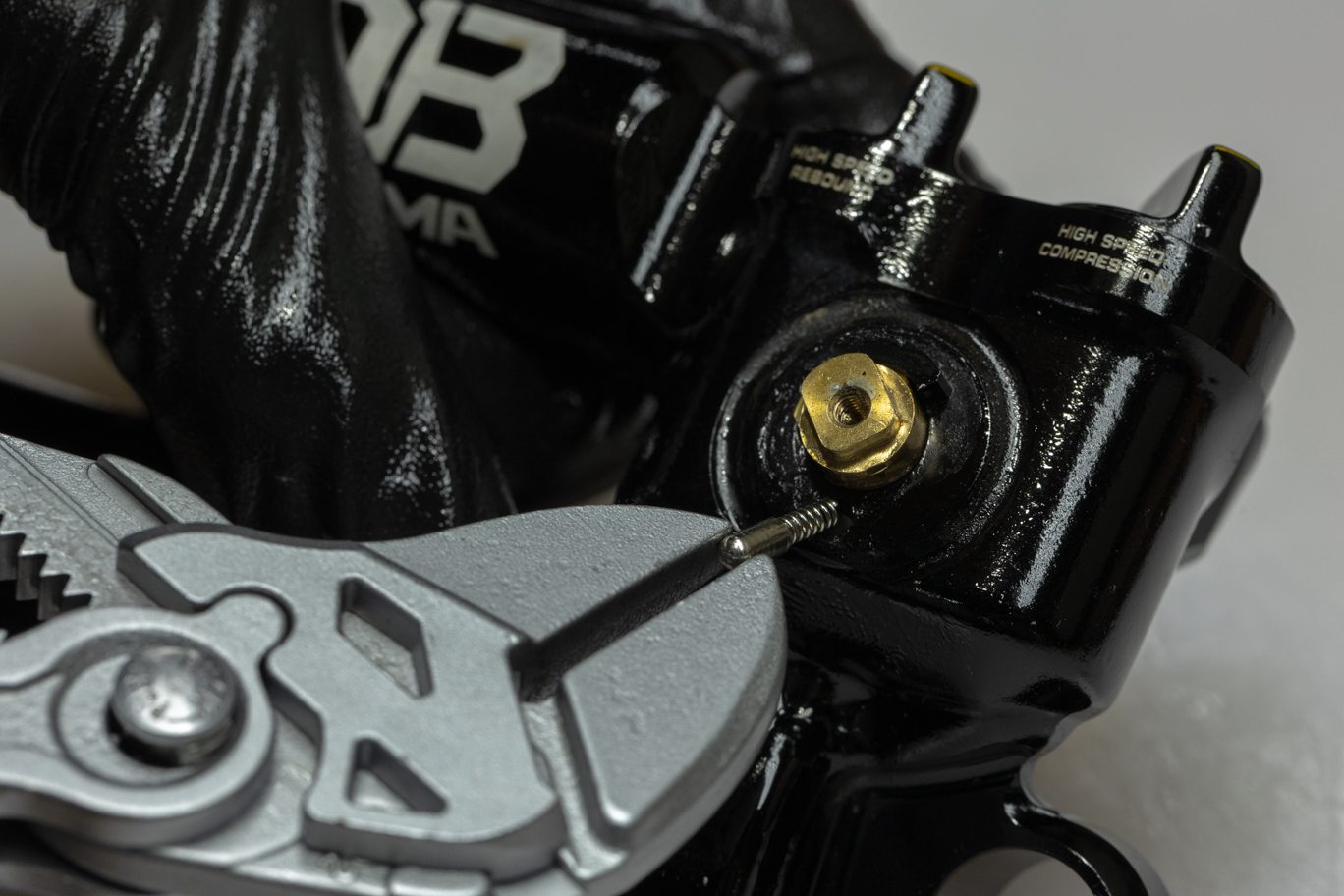
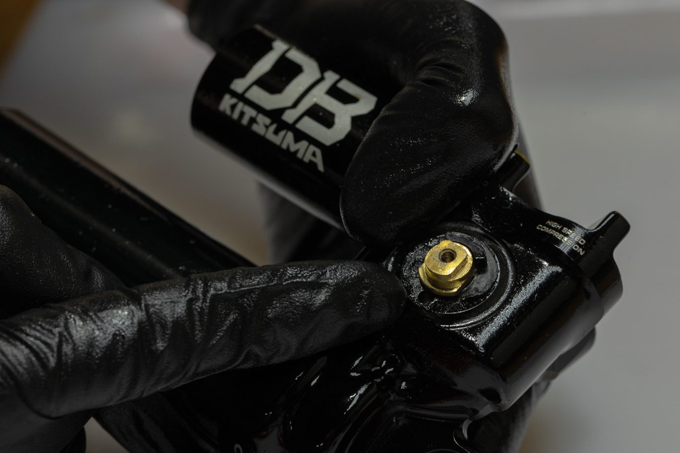
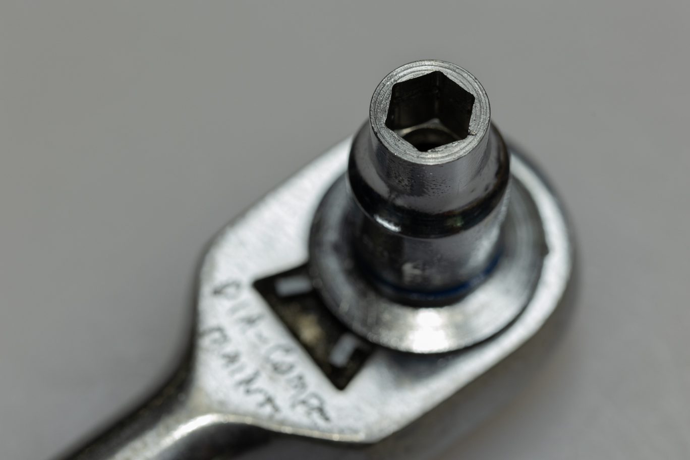
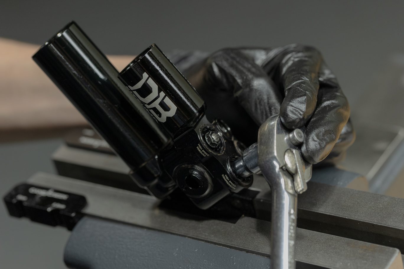
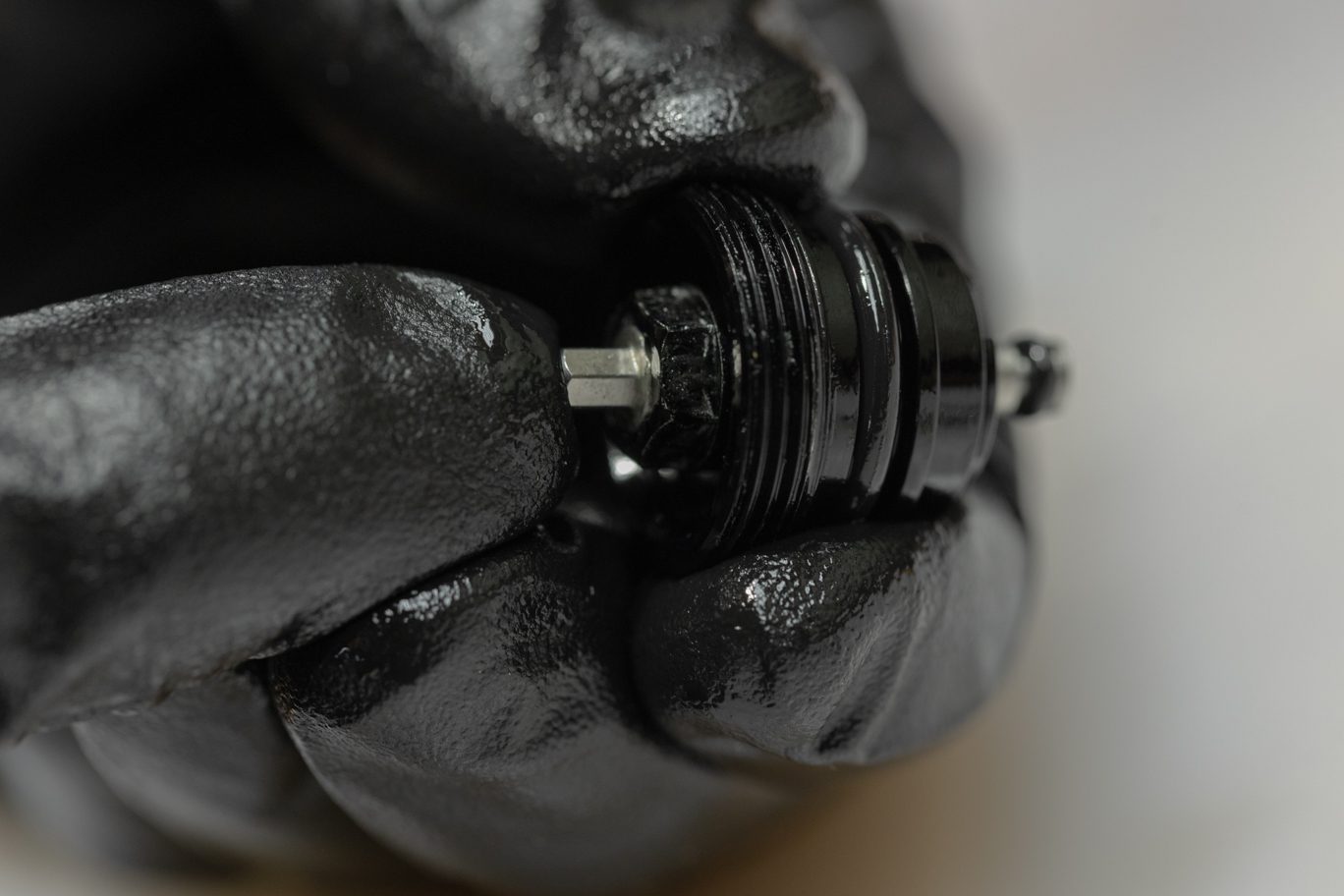
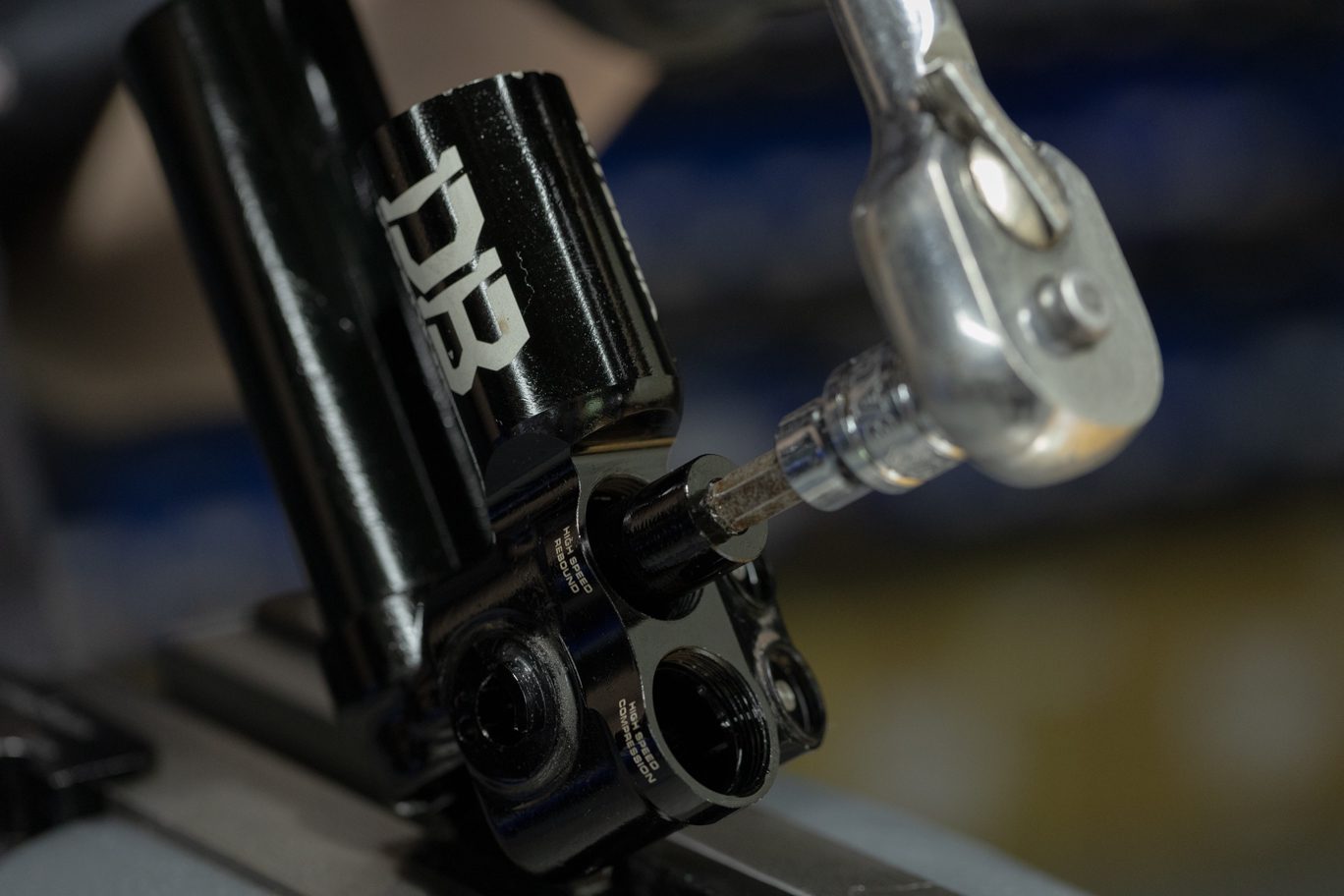
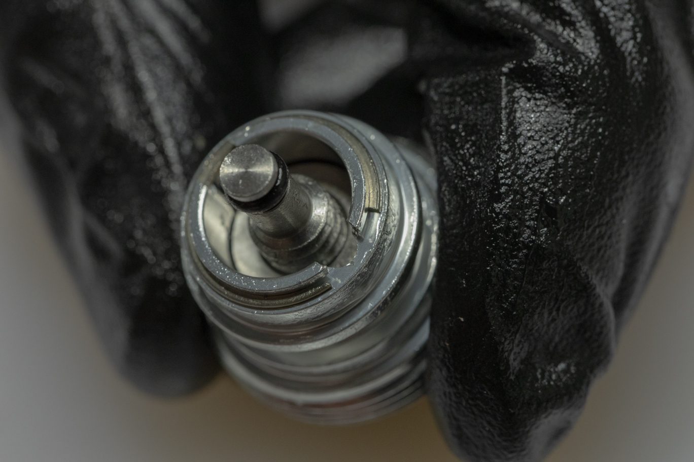
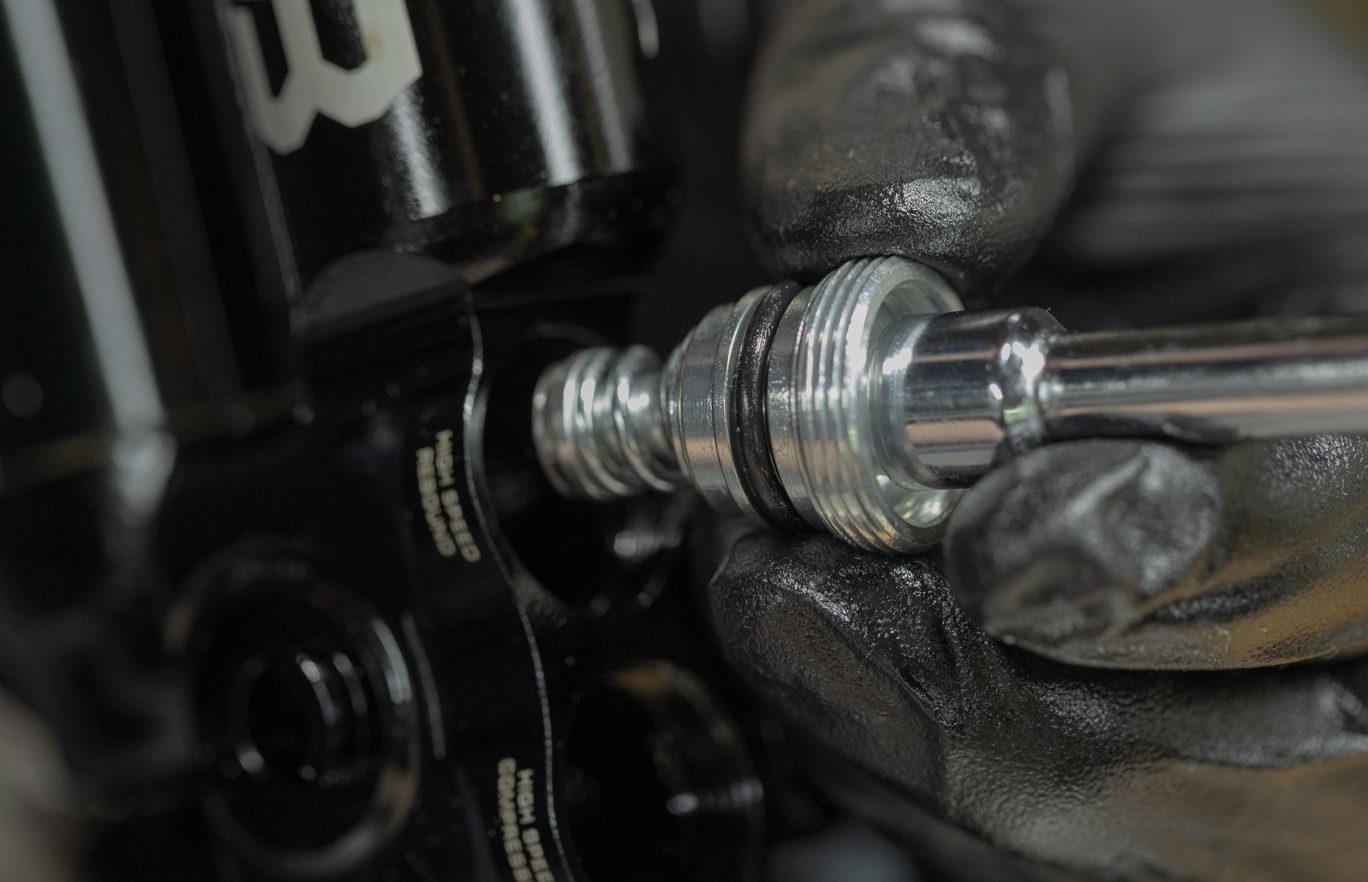
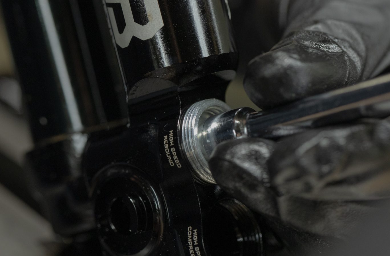
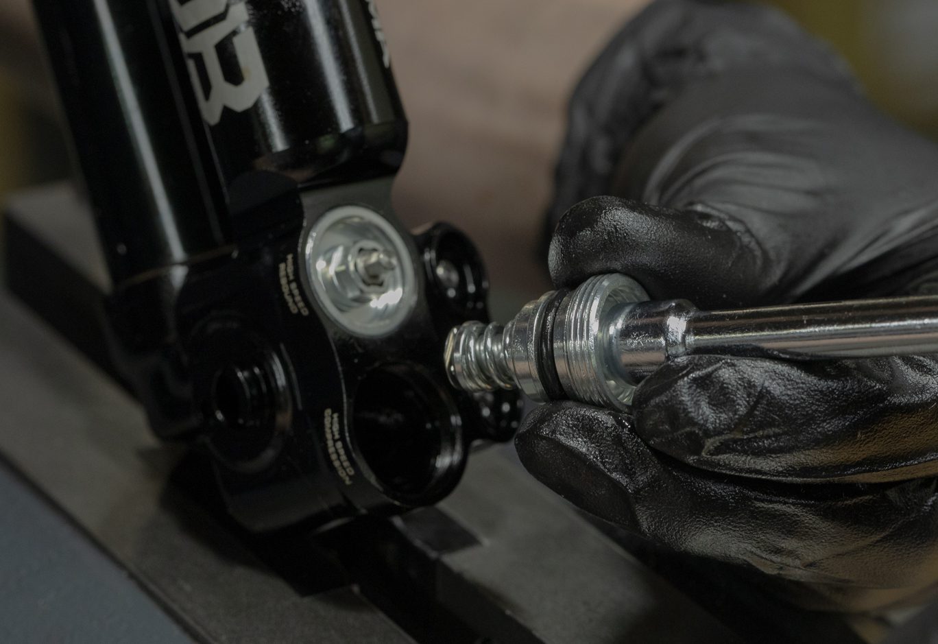
Using 8mm socket, remove high speed adjuster housing. Apply heat to aid removal.
***Note high speed adjuster housing may also be silver.***
TSB039 – Kitsuma High Speed Cap (ACD0275) Loctite Removal from Installation
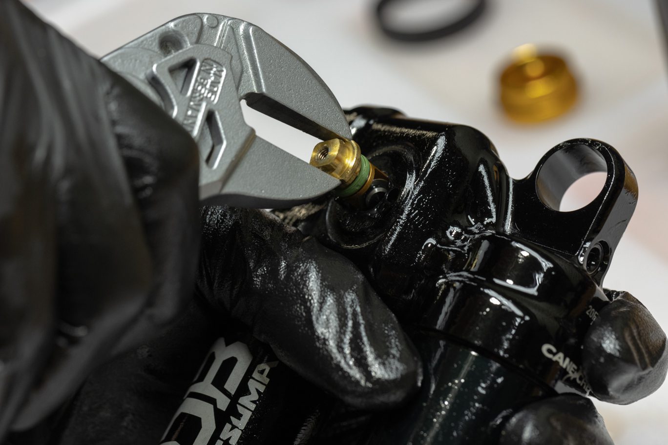
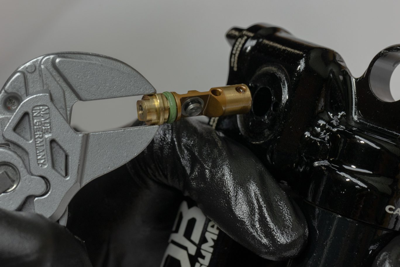
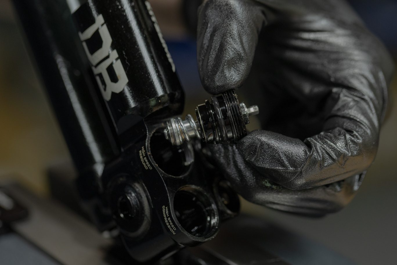
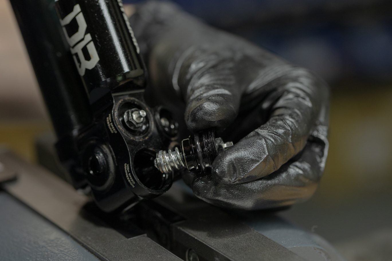
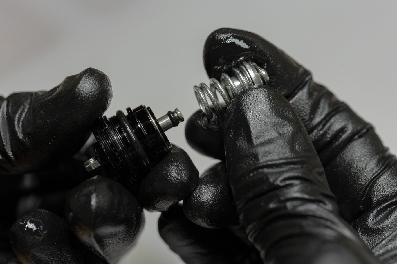
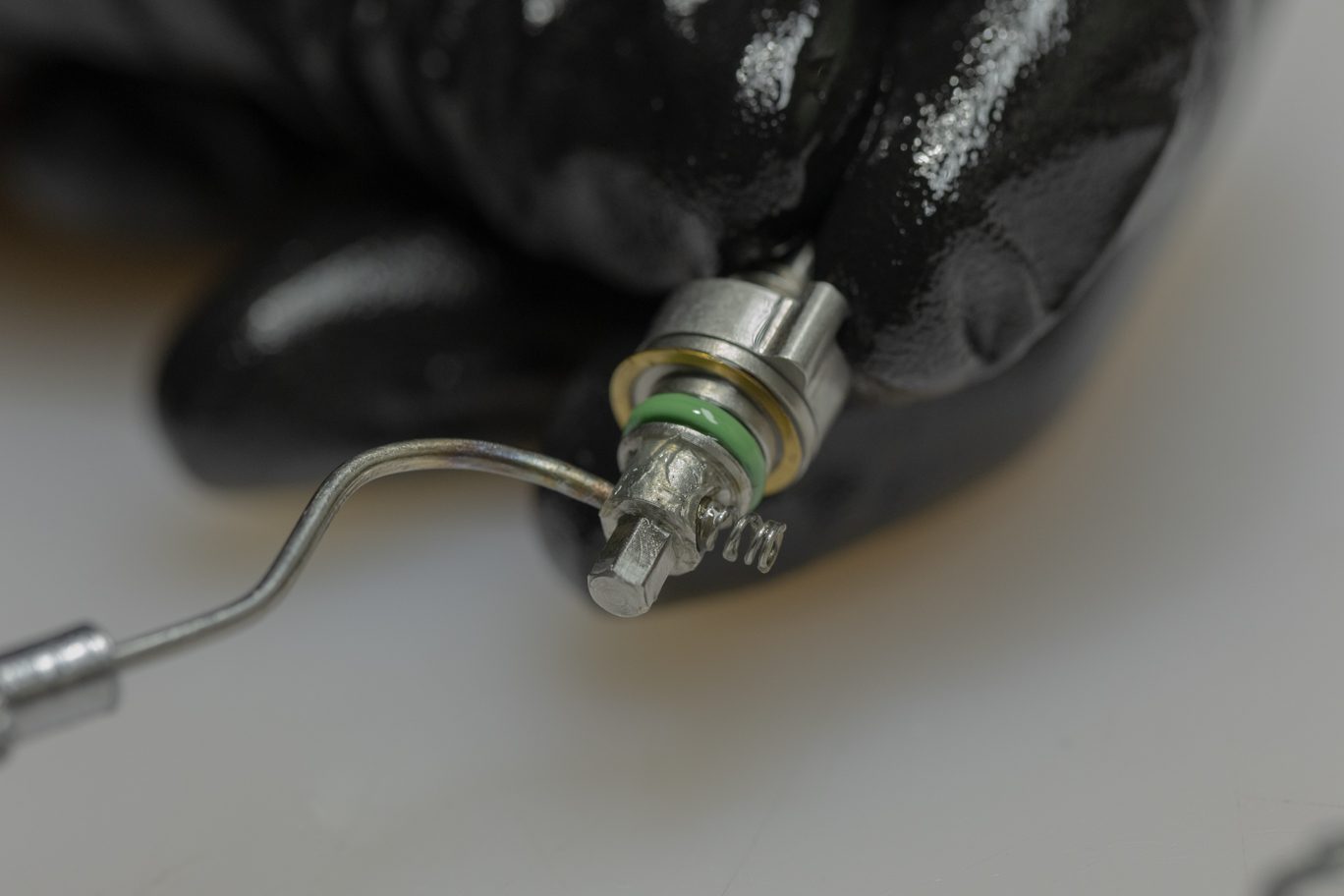
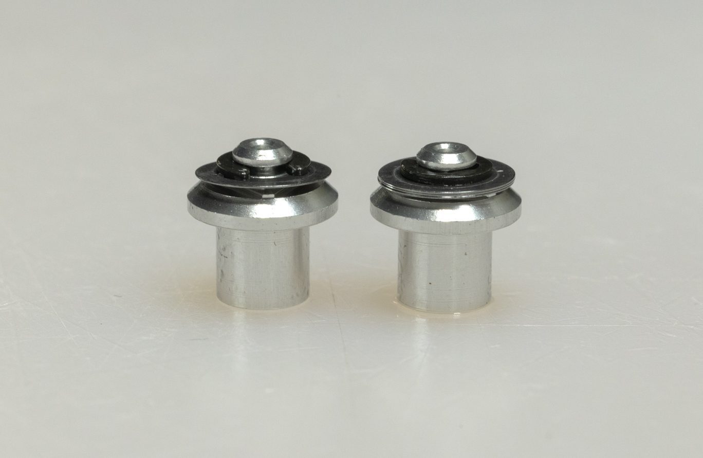
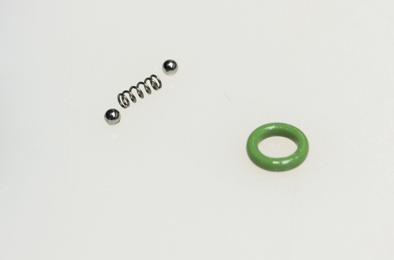
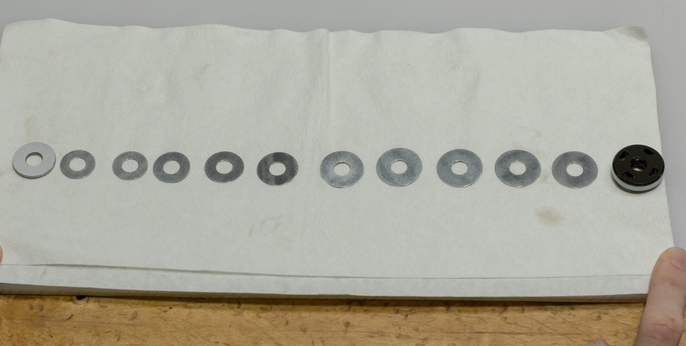
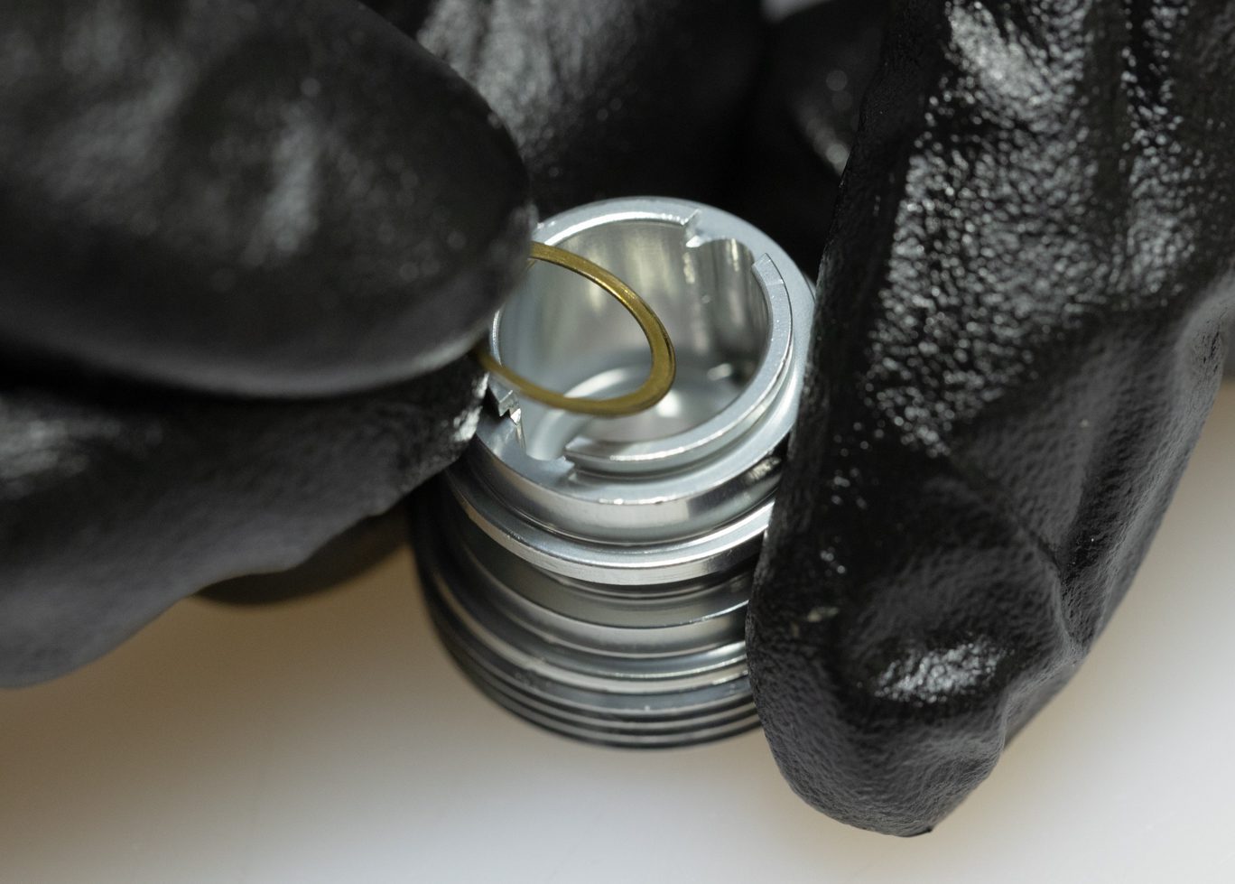
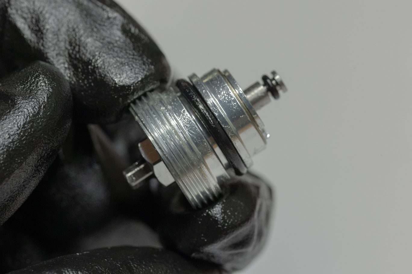
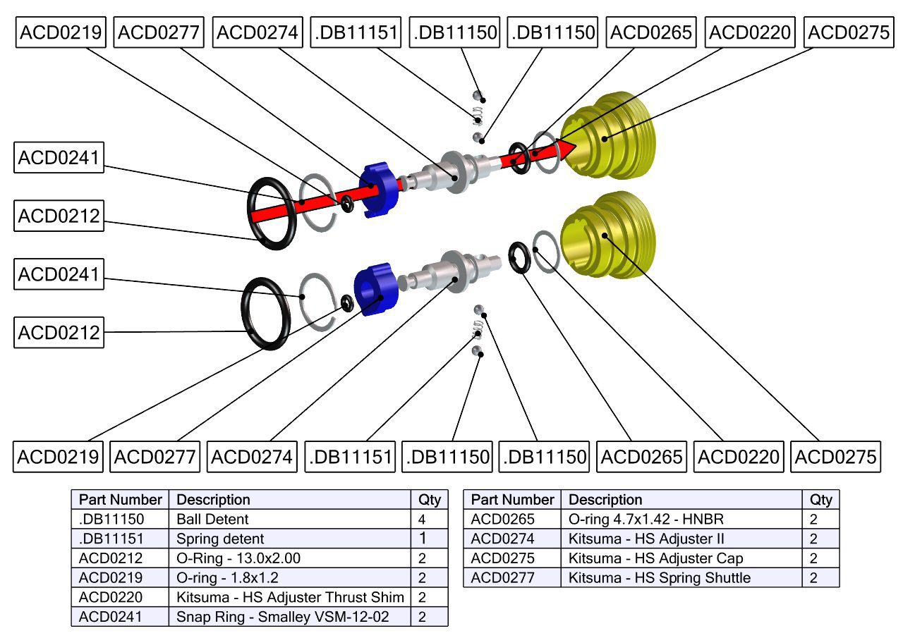
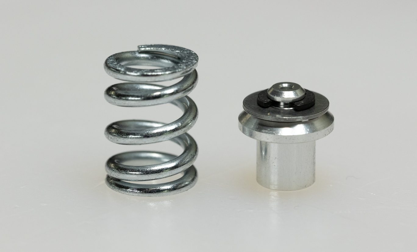
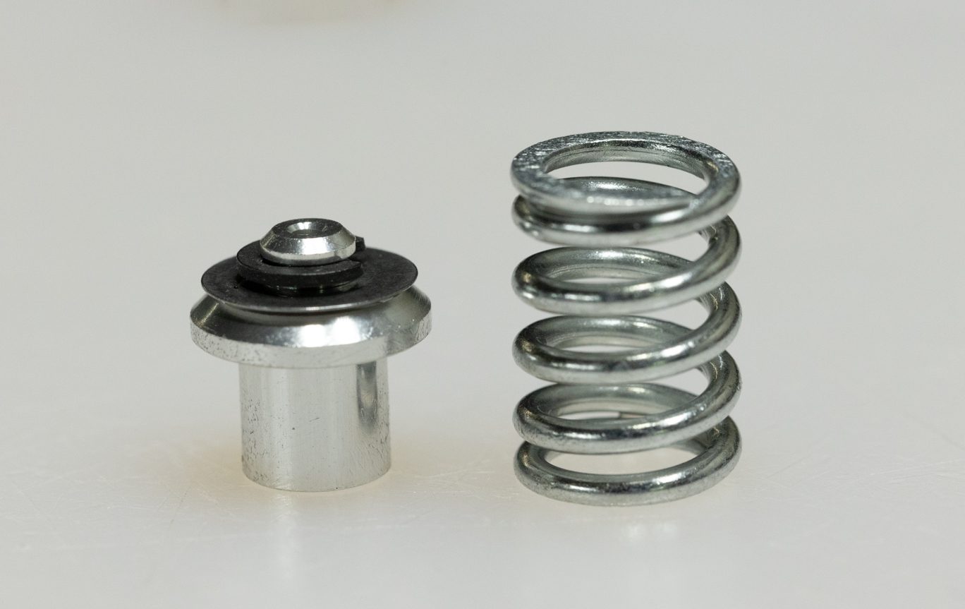
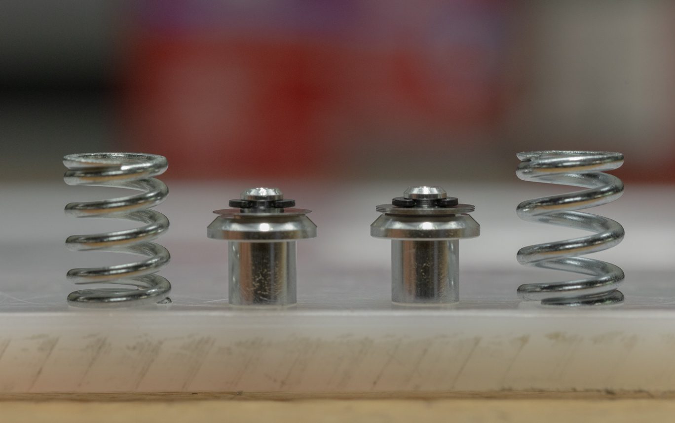
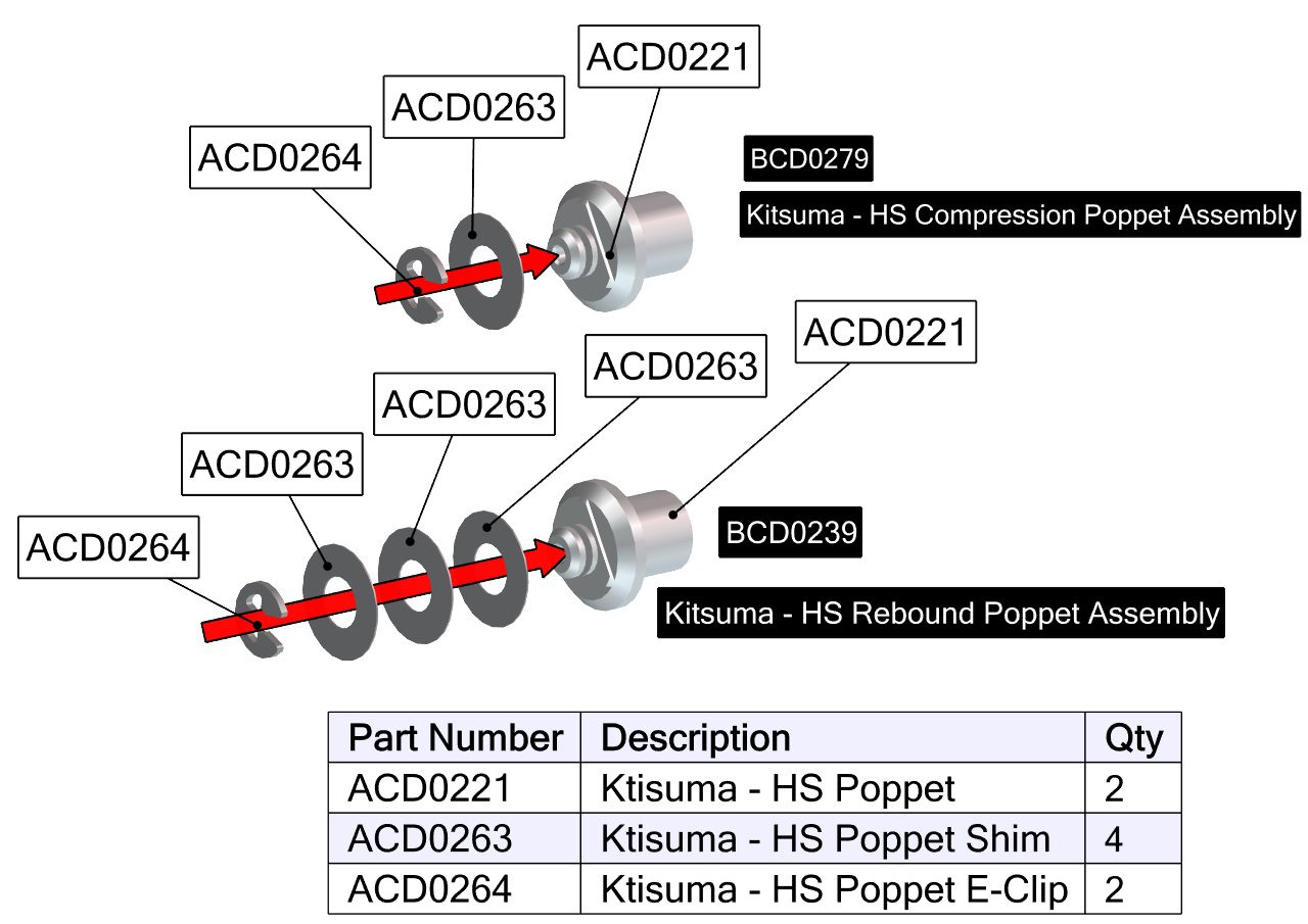
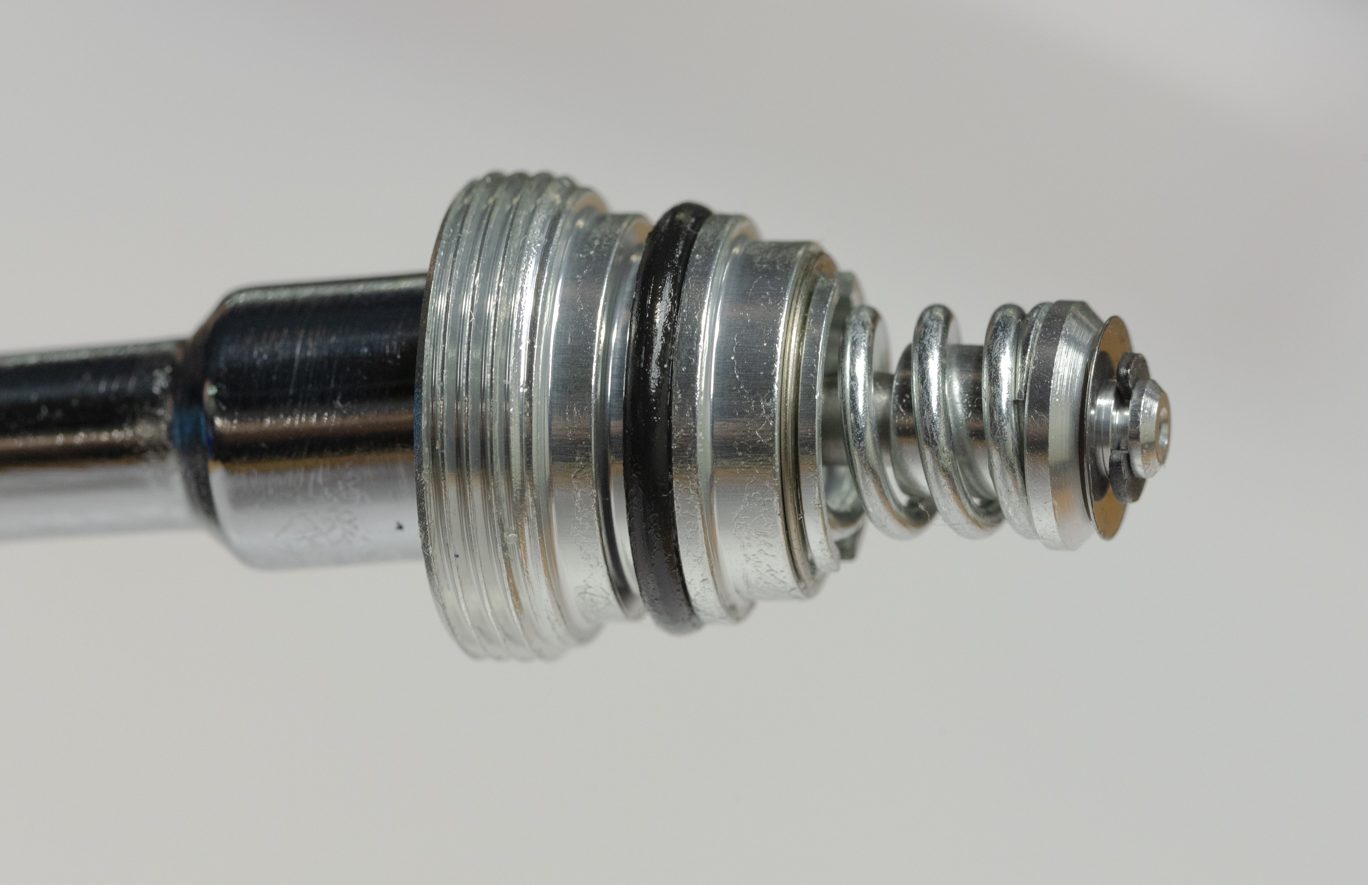
Press out detent spring and balls. Unthread shuttle, remove gold shim and remove both o-rings. Discard o-rings. Note the differences between the poppets and springs from the compression and rebound sides.
TSB038 – Kitsuma HSR Revalve
To address knocking coming from high speed valve seats.
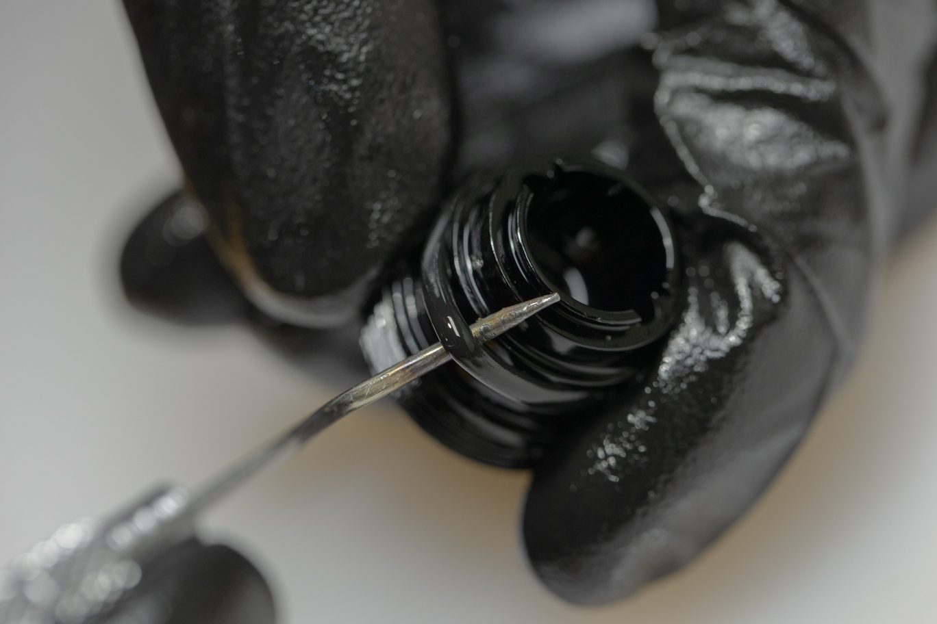
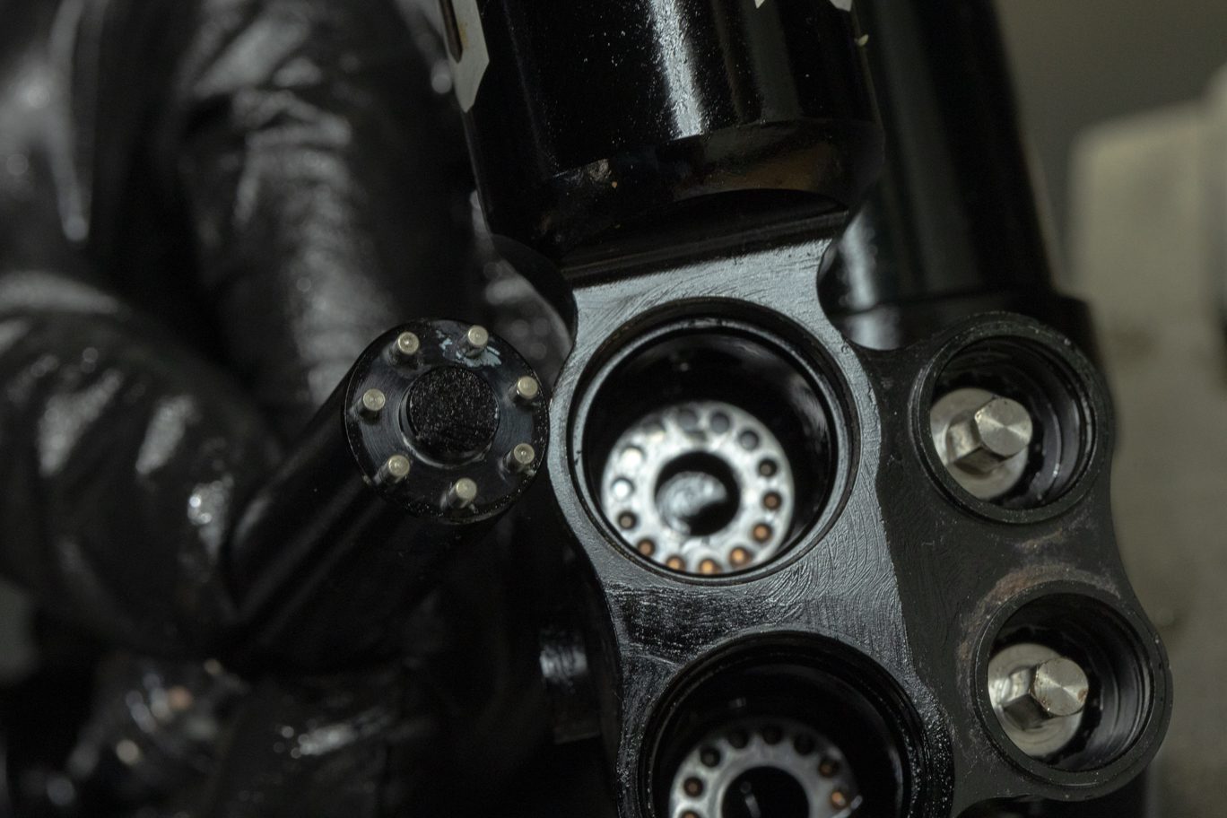
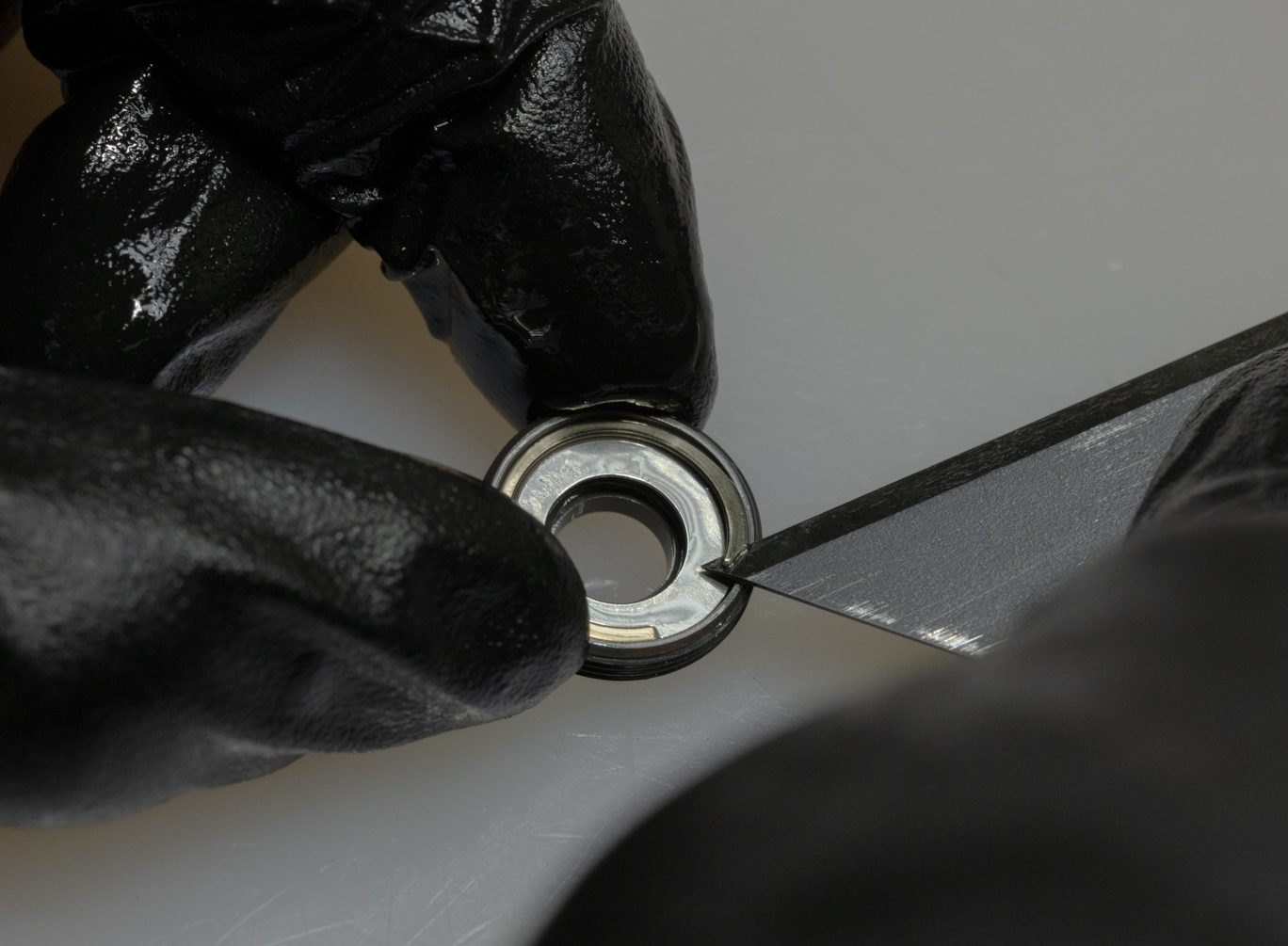
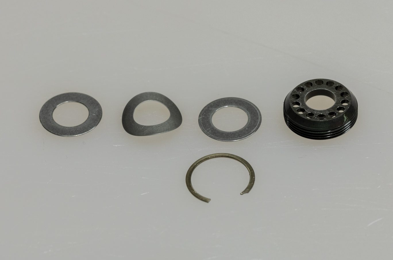
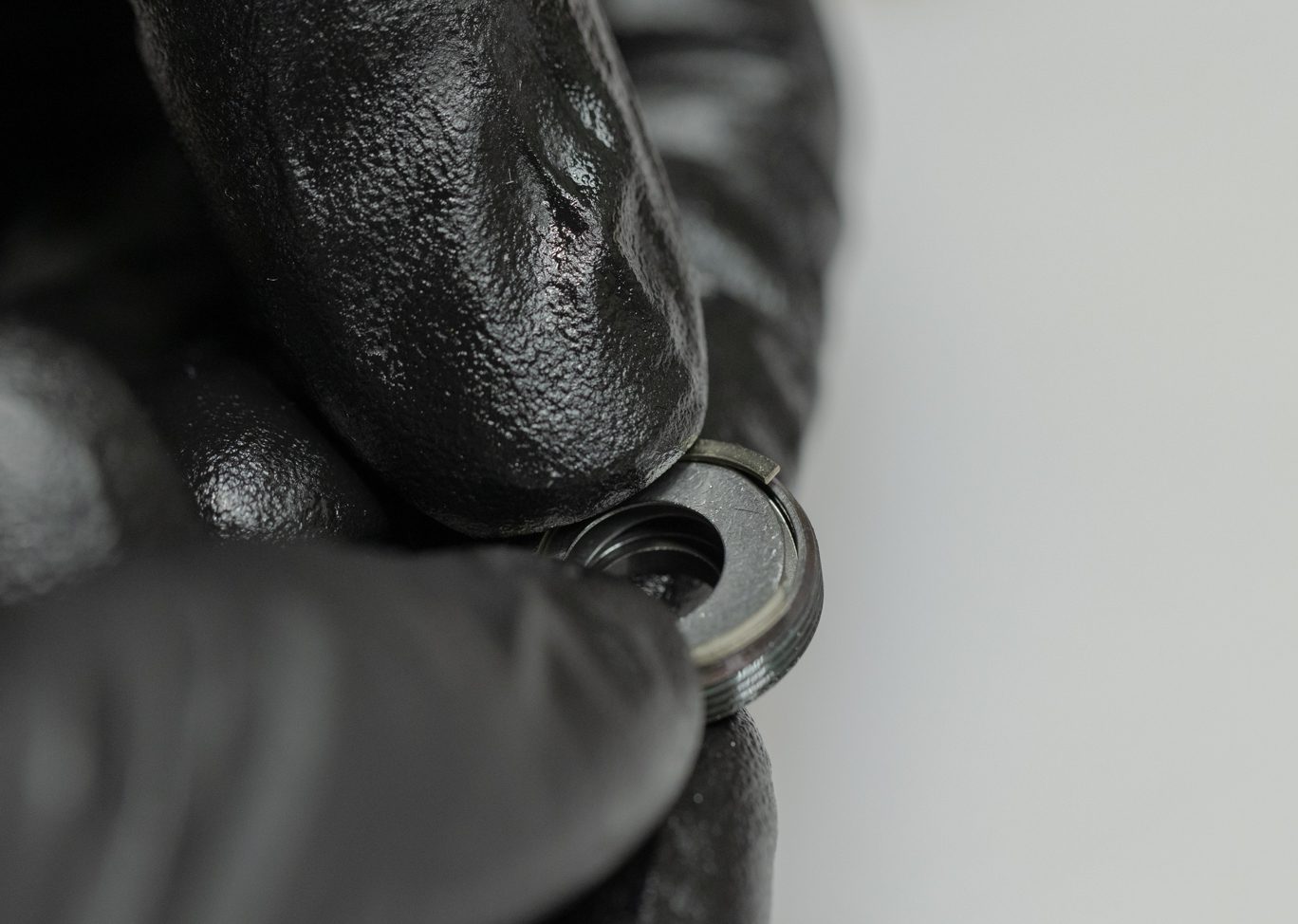
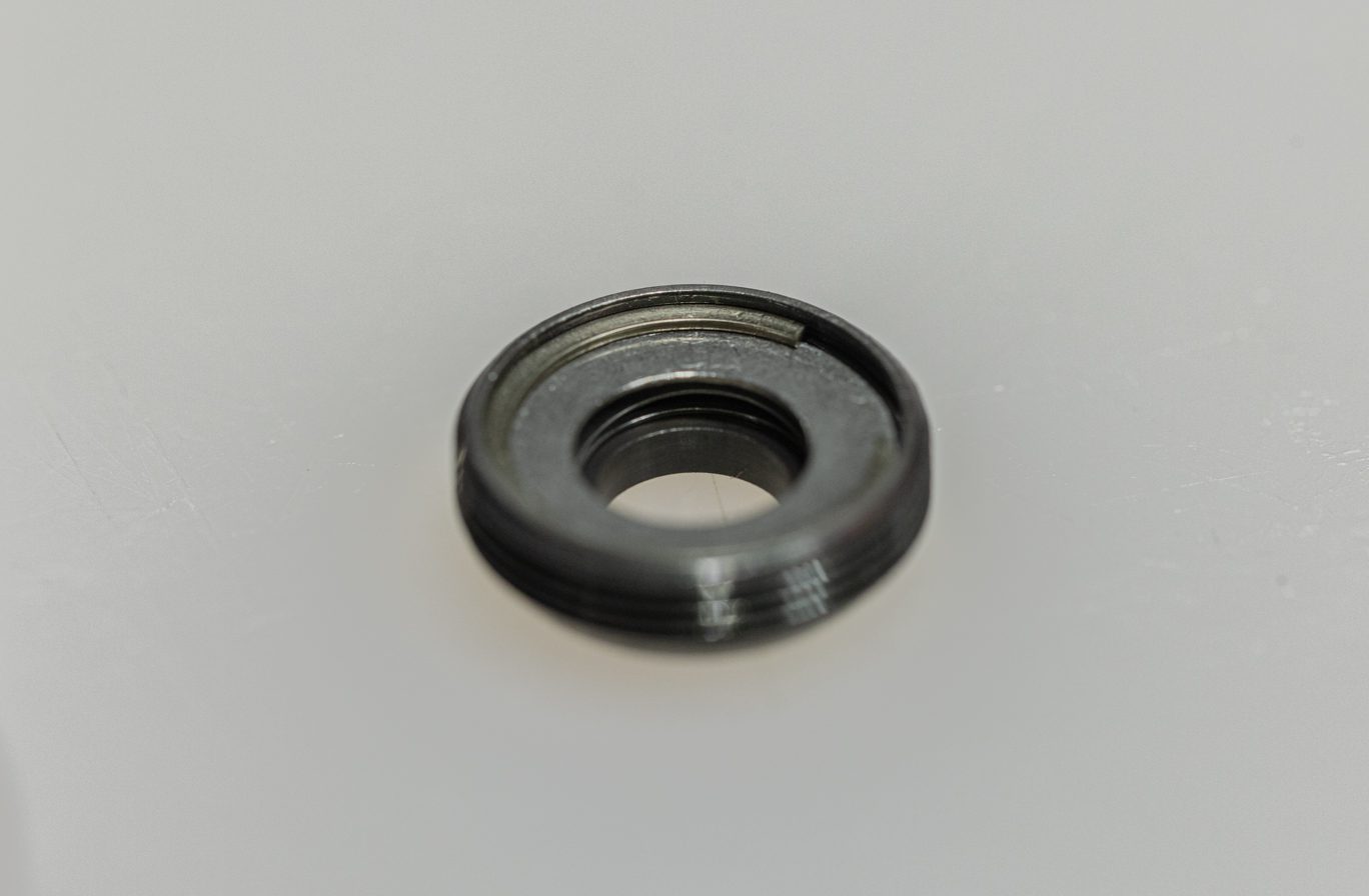
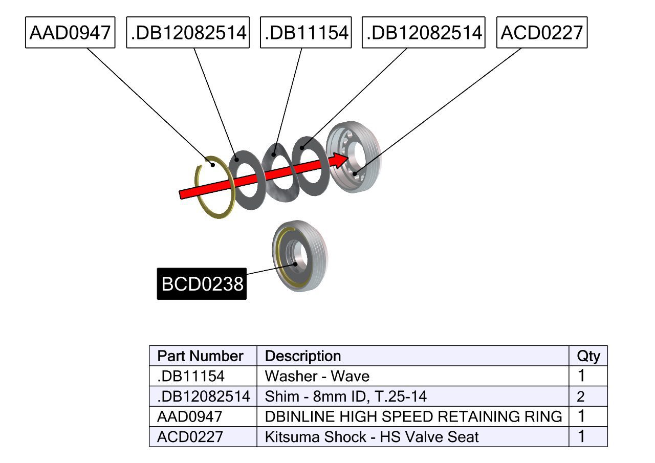
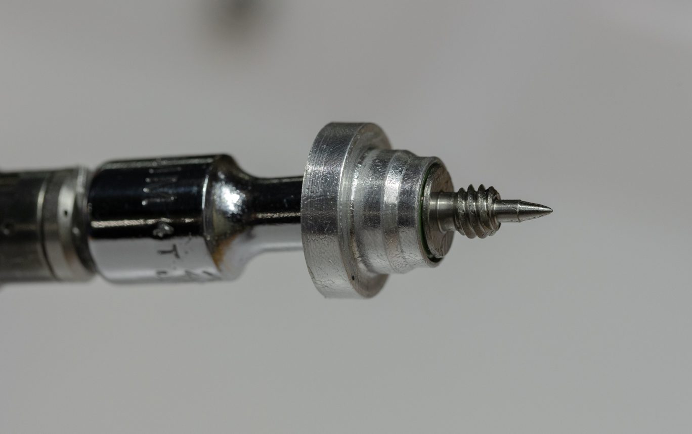
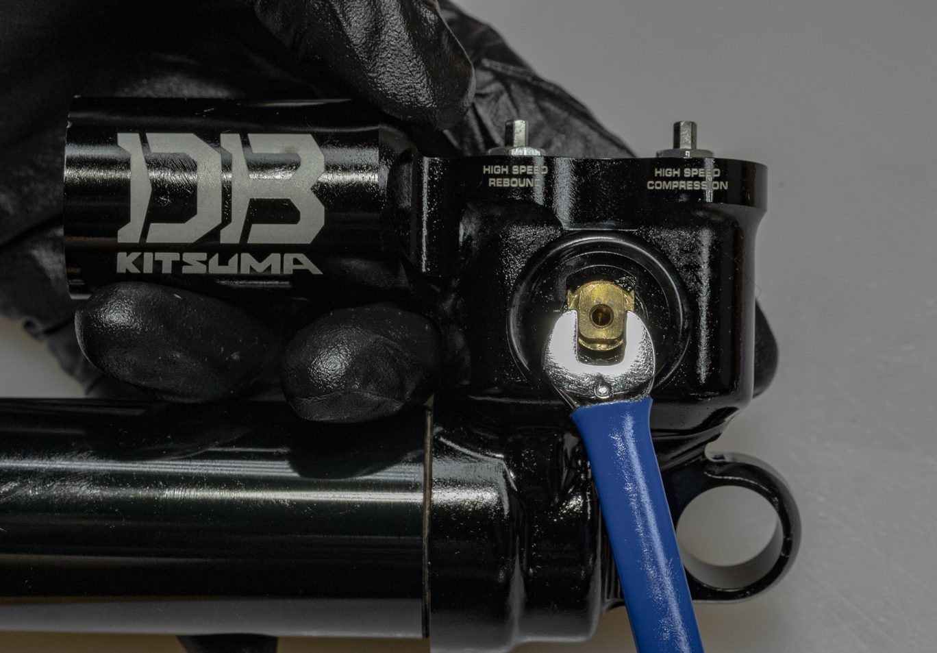
Using Valve Seat tool (AAD2465), remove the high speed valve seats. Take care to seat the tool properly and use even pressure to avoid damaging seats and tool. Clean valve seats. Valve seats can be disassembled by removing circlip. If valve seat housing, washers or shims are damaged, the entire assembly (BCD0238) can be replaced.
***Do not attempt to remove the low speed needle seats. If damaged, then complete shock must be replaced.***
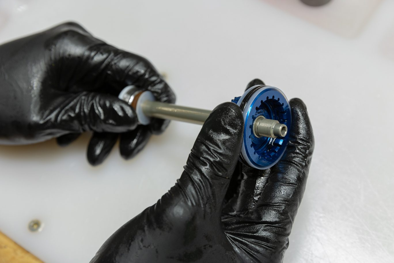
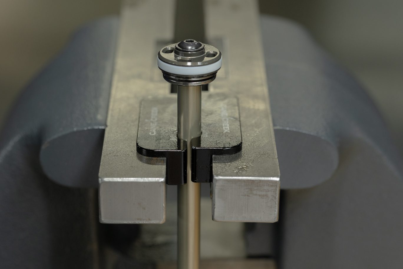
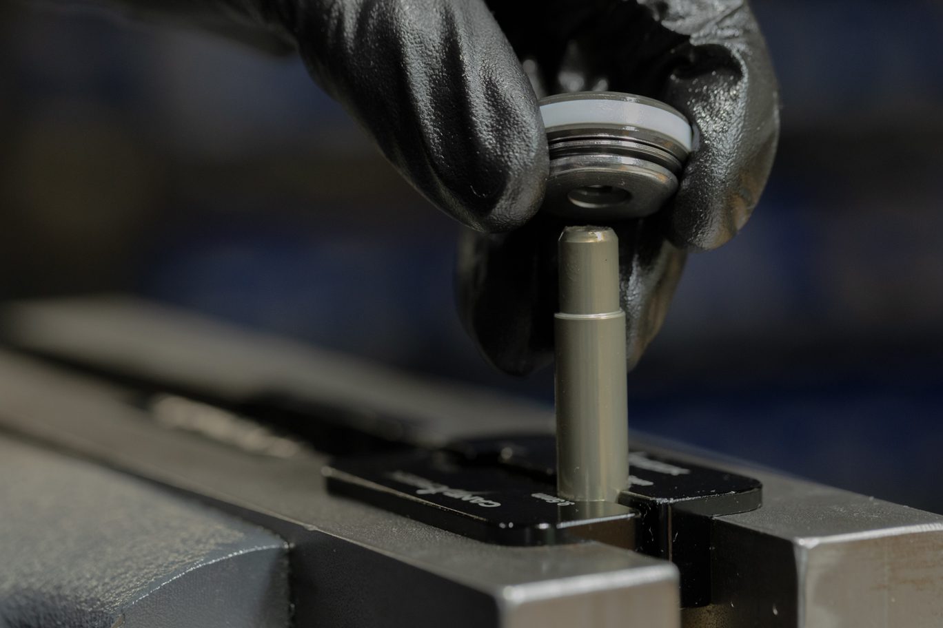
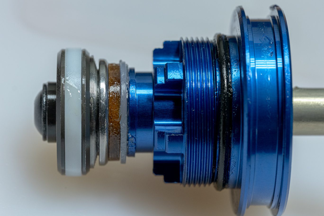
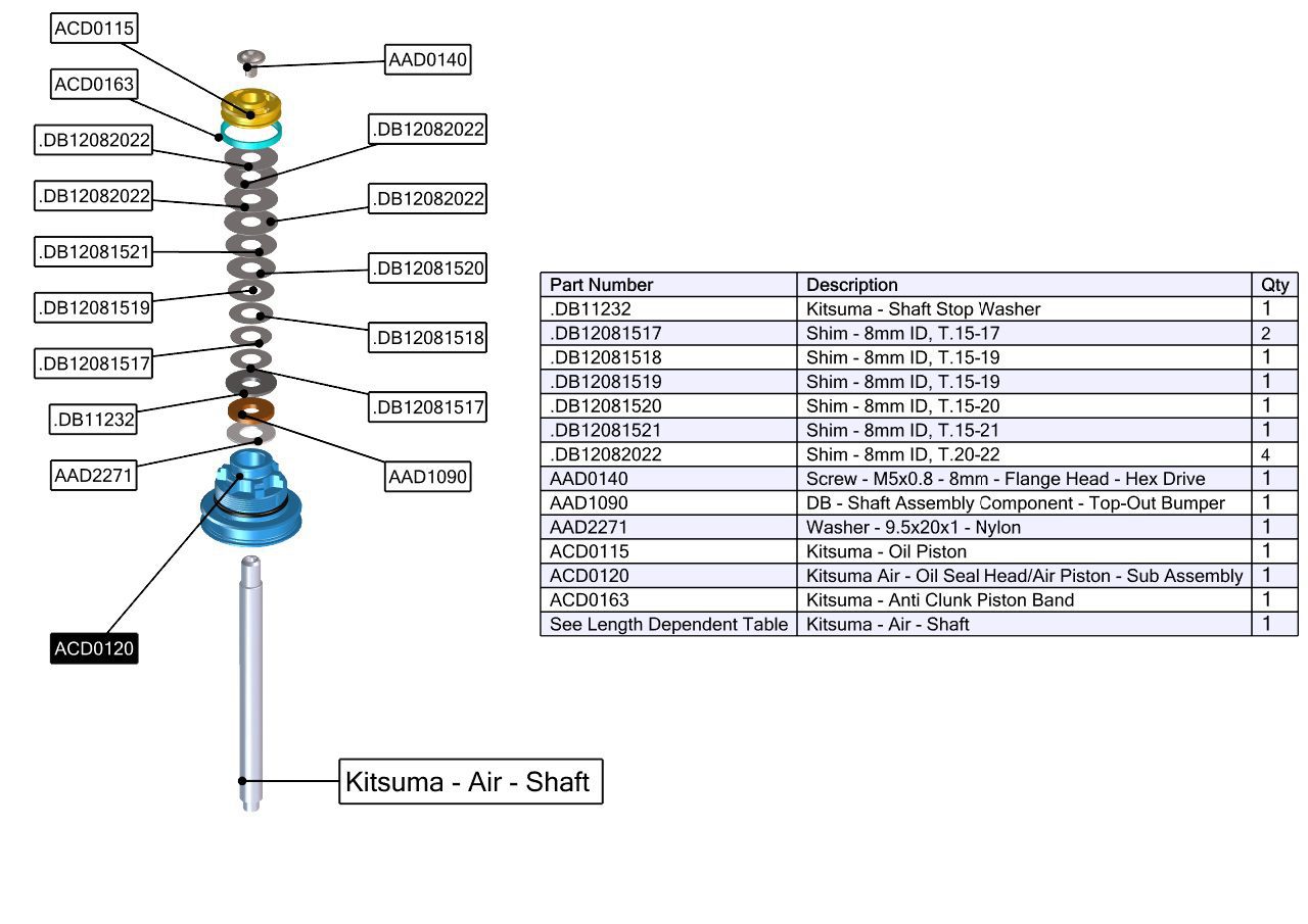
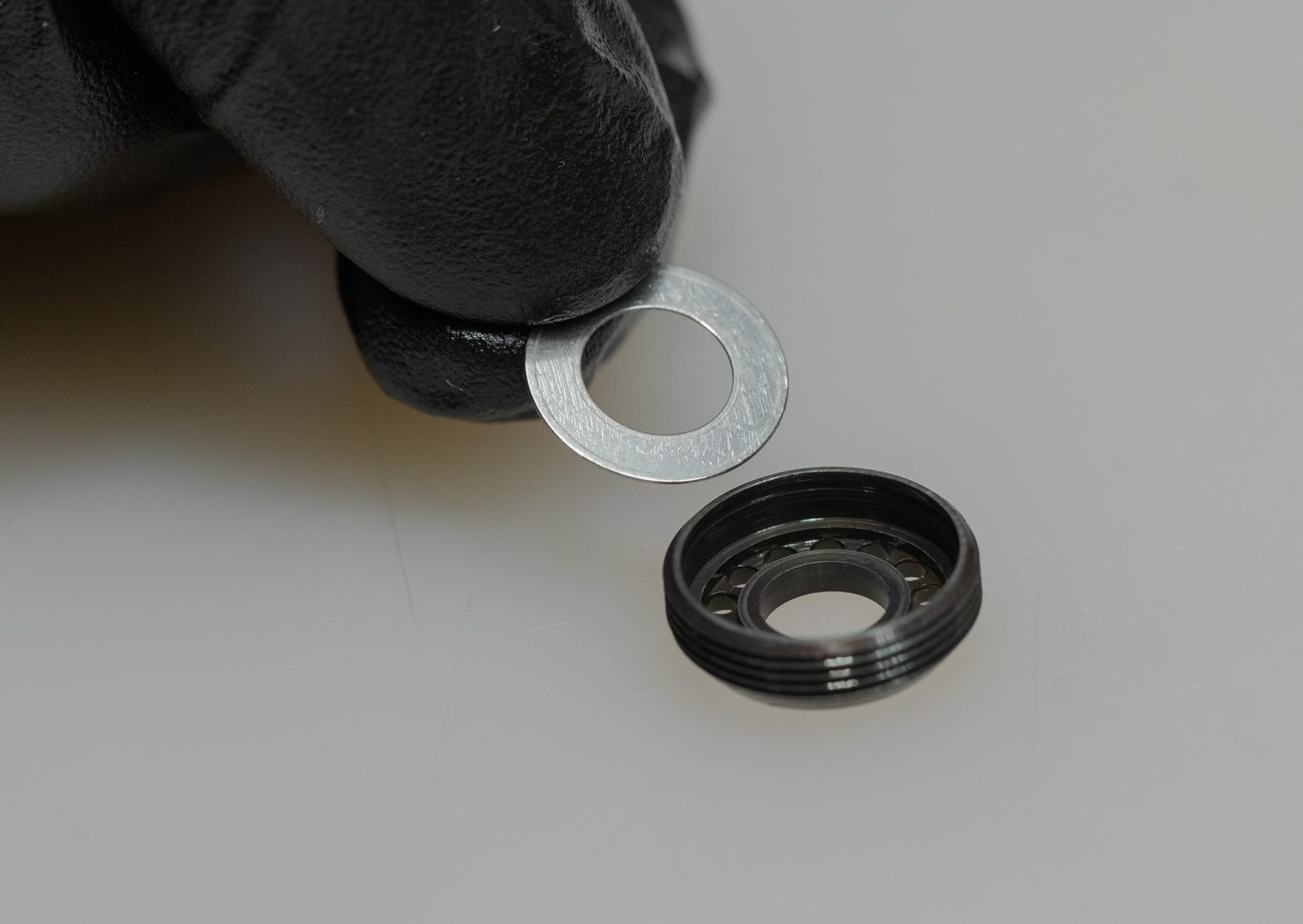
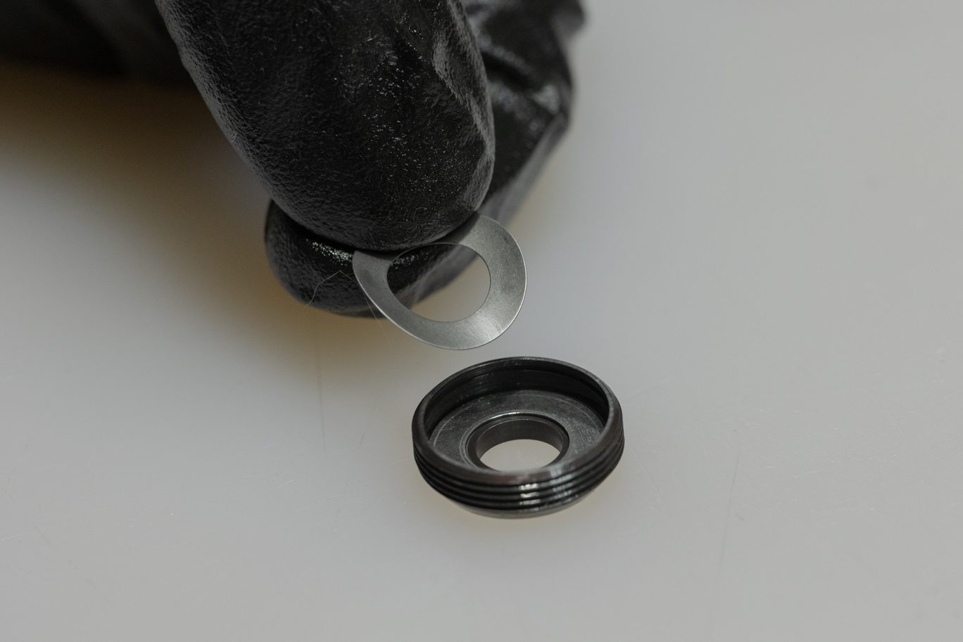
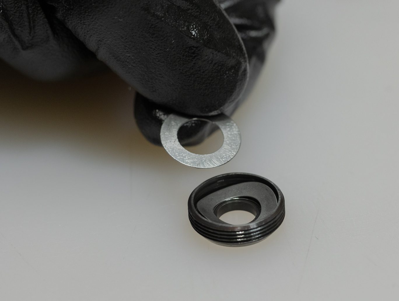
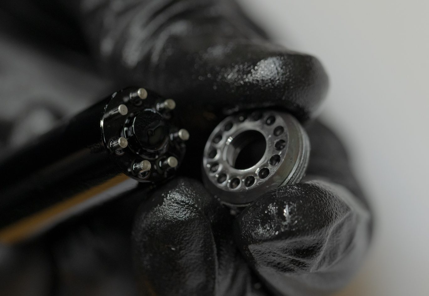
Clamp shaft in shaft vise. Using 3mm Allen, loosen and remove shaft bolt. Remove piston assembly from shaft and inspect. For 100 hour service, simply clean piston. For 200 hour service or if any piston band wear is present, discard entire piston assembly. Note orientation of the shims. Flip check face on reinstall if showing signs of wear. Inspect shaft for any wear or damage.
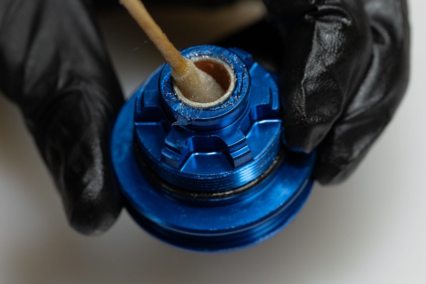
Thoroughly grease quad ring (AAD1806) and install between bushings in oil seal head. Thoroughly grease external o-ring (.DB11108) and install it past the threads on oil seal head.
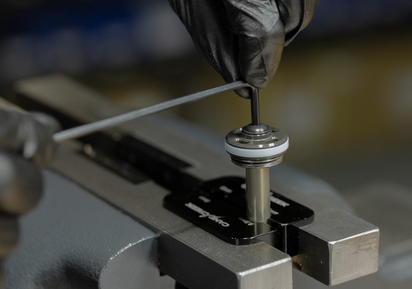
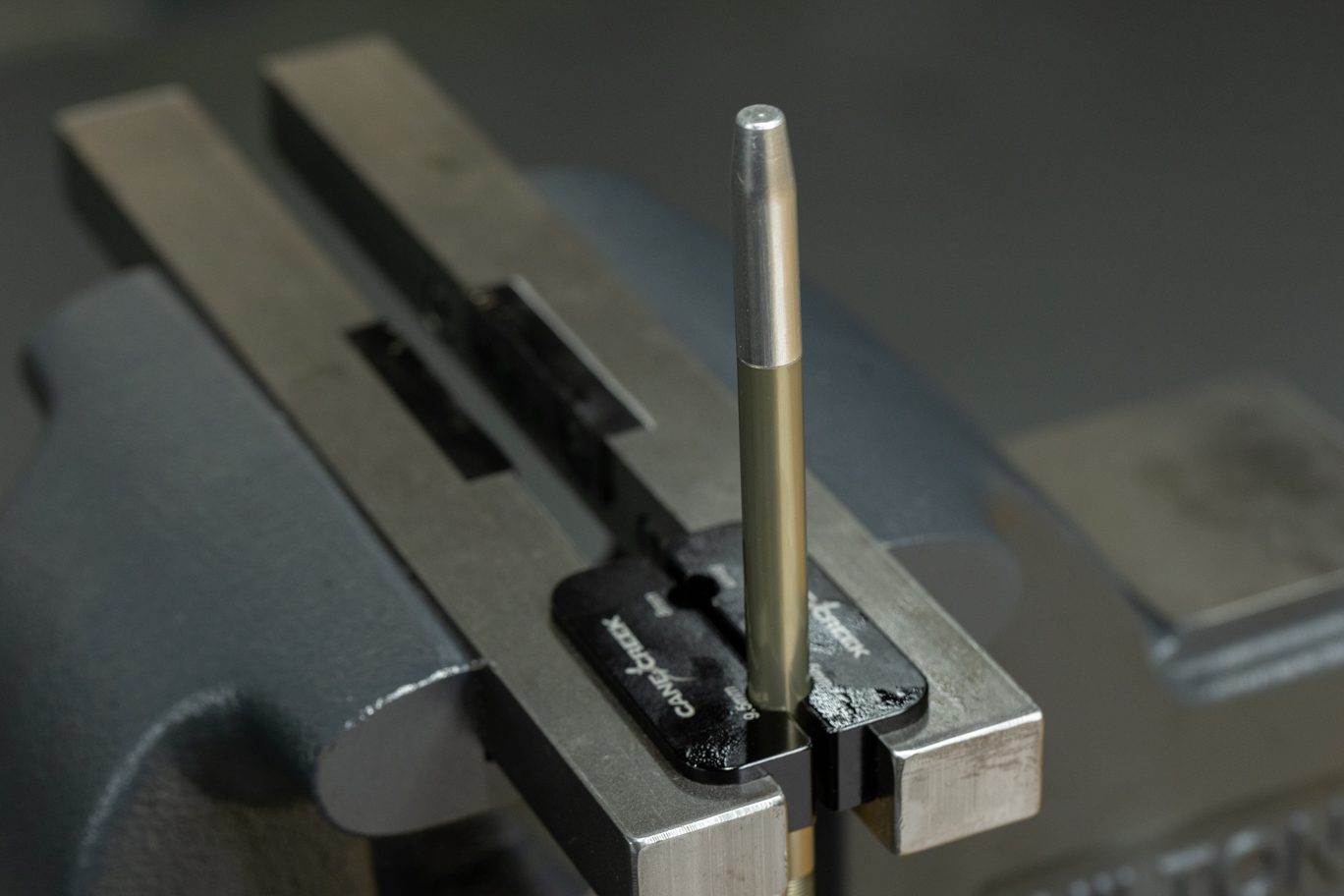
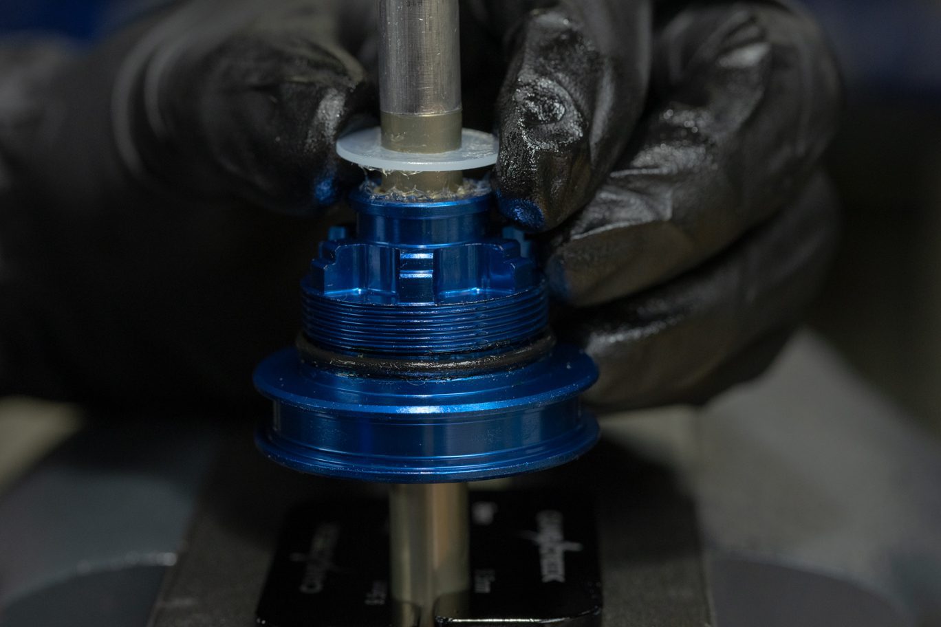
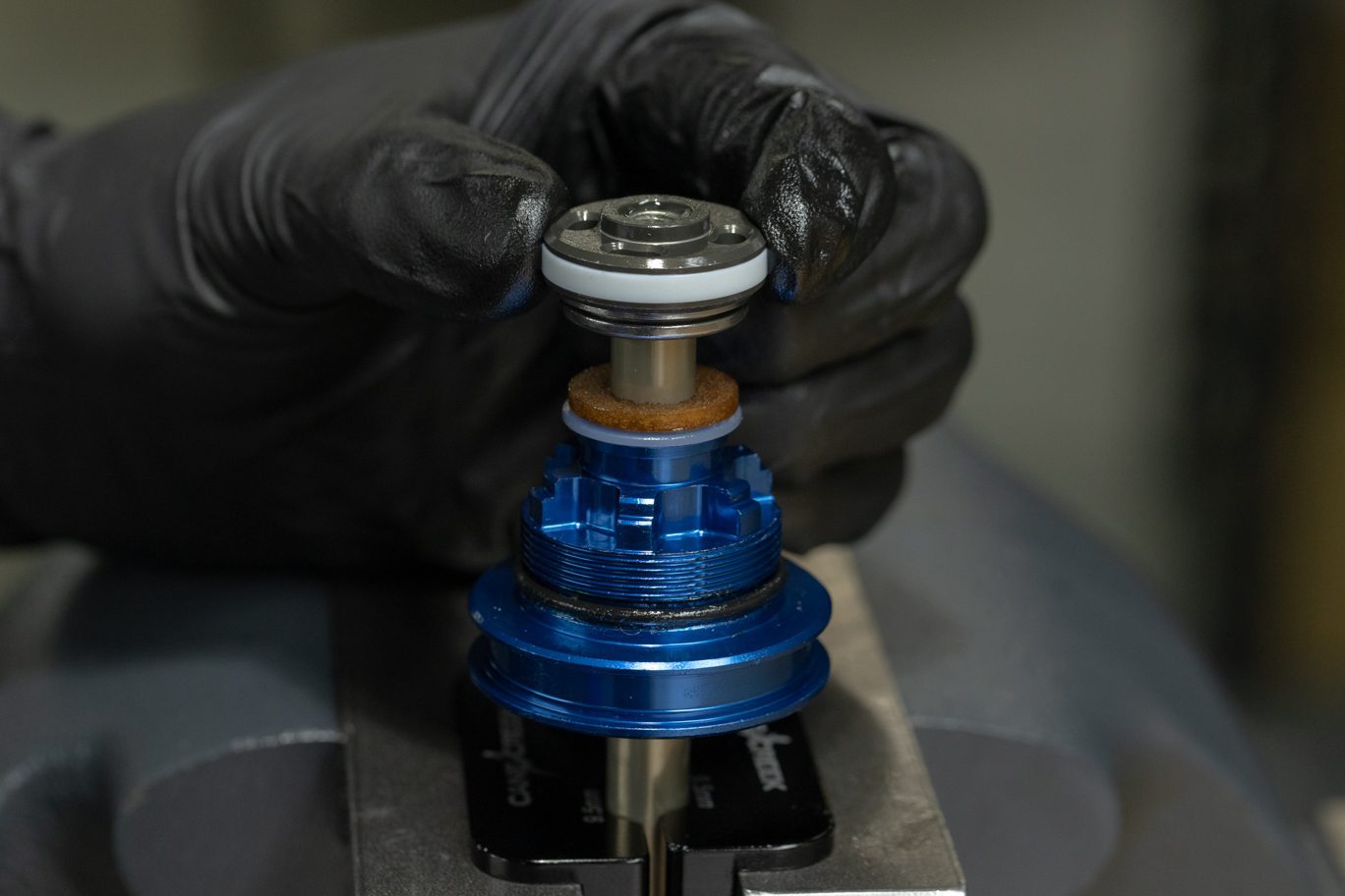
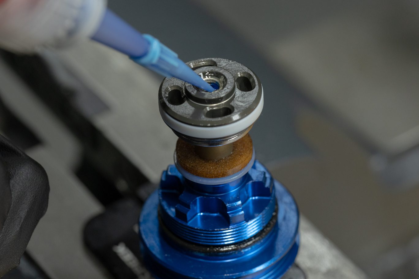
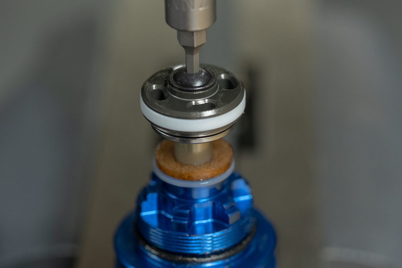
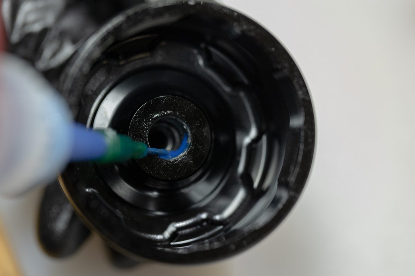
Clamp shaft in vise. Thoroughly grease bushings and quad ring on serviced (100 hour) or new (200 hour) oil seal head (ACD0120). Using 9.5mm shaft bullet, install oil seal head. Reinstall stop washer, shim stack and piston – either original (100 hour) or new (200 hour – ACD0327). Apply blue Loctite (243) to threads in shaft, taking care to not over fill. Install shaft bolt. Torque to 5 Nm with 3mm Allen.
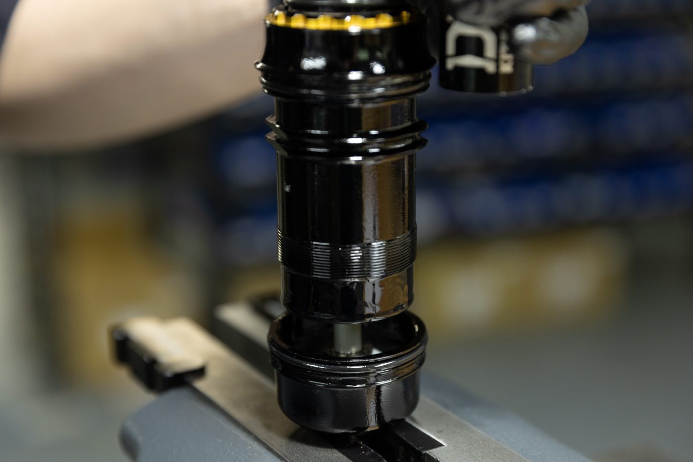
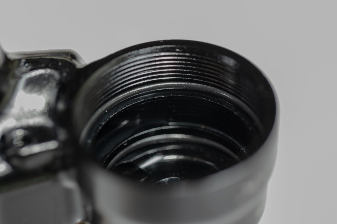
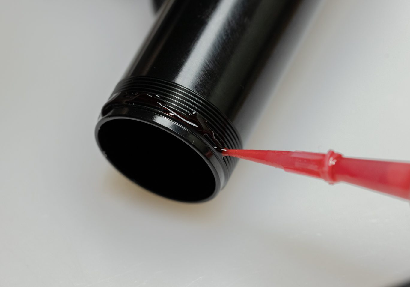
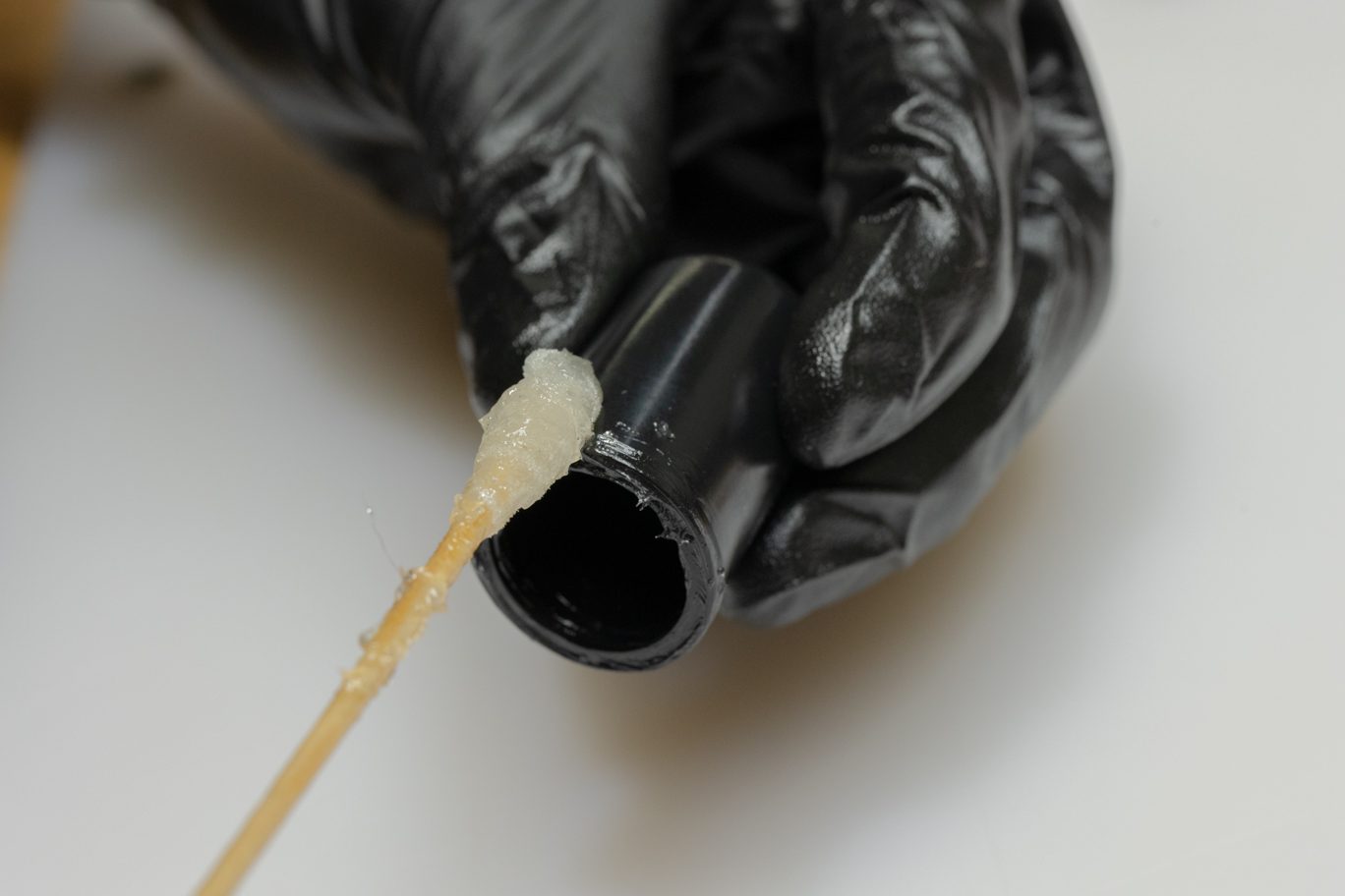
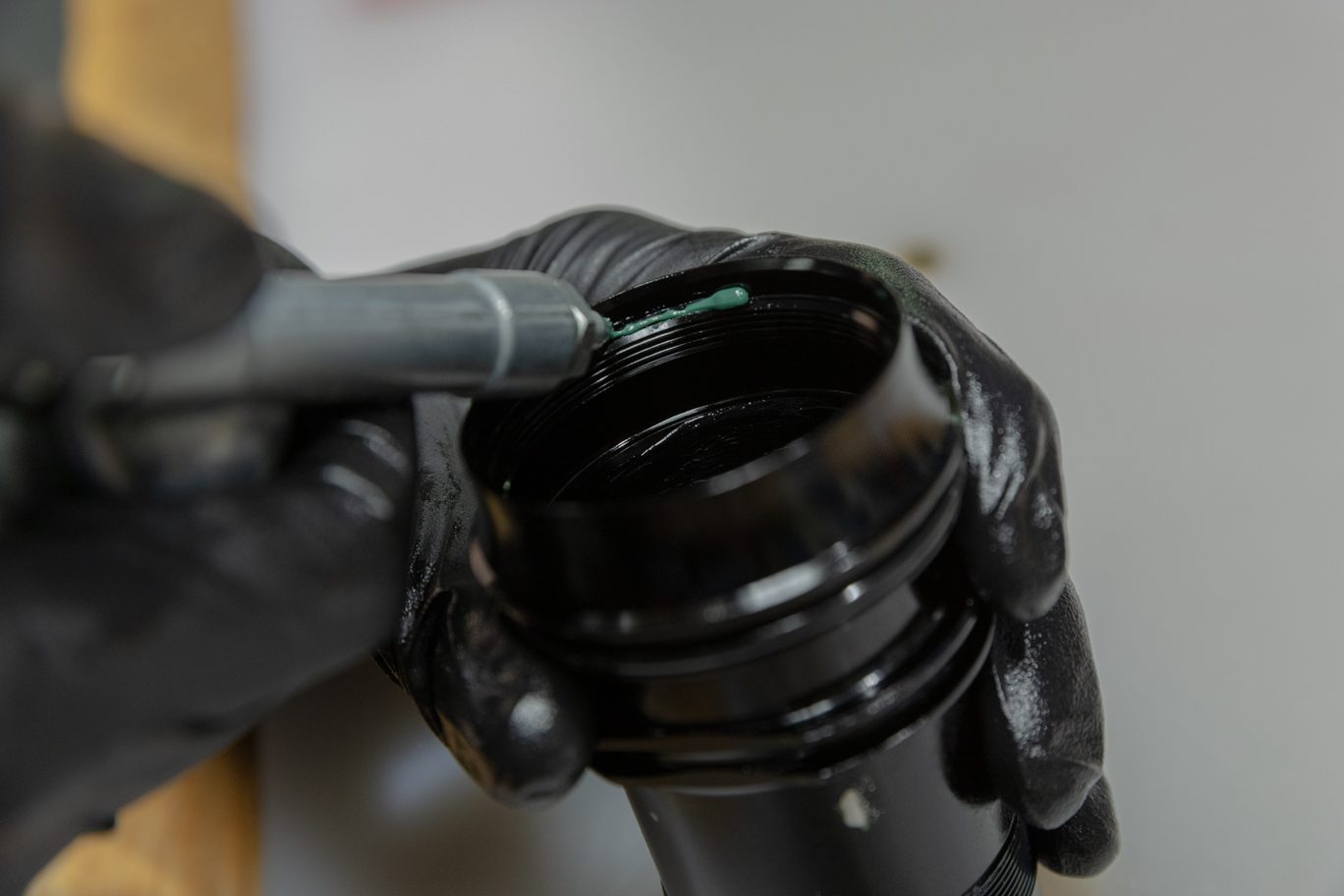
Lightly grease and install valve body o-rings (.DB11109 & .DB11110) into valve body. Clamp valve body in vise. Apply 3-5 cms of red Loctite (263) to threads of outer damper tube. Hand thread damper tube into valve body. Thoroughly clean any grease or oil from damper tube. Use strap wrench to tighten damper tube.
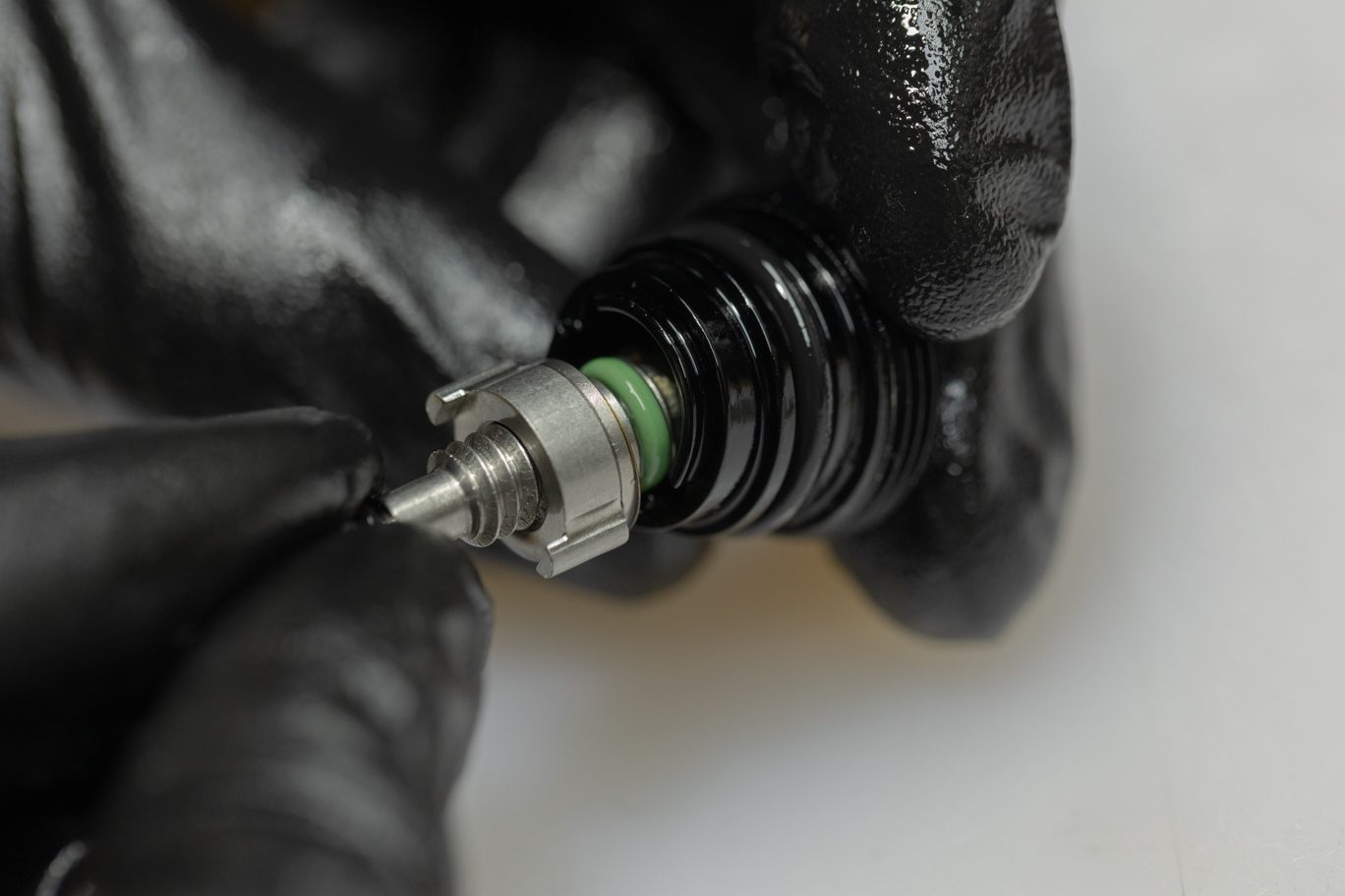
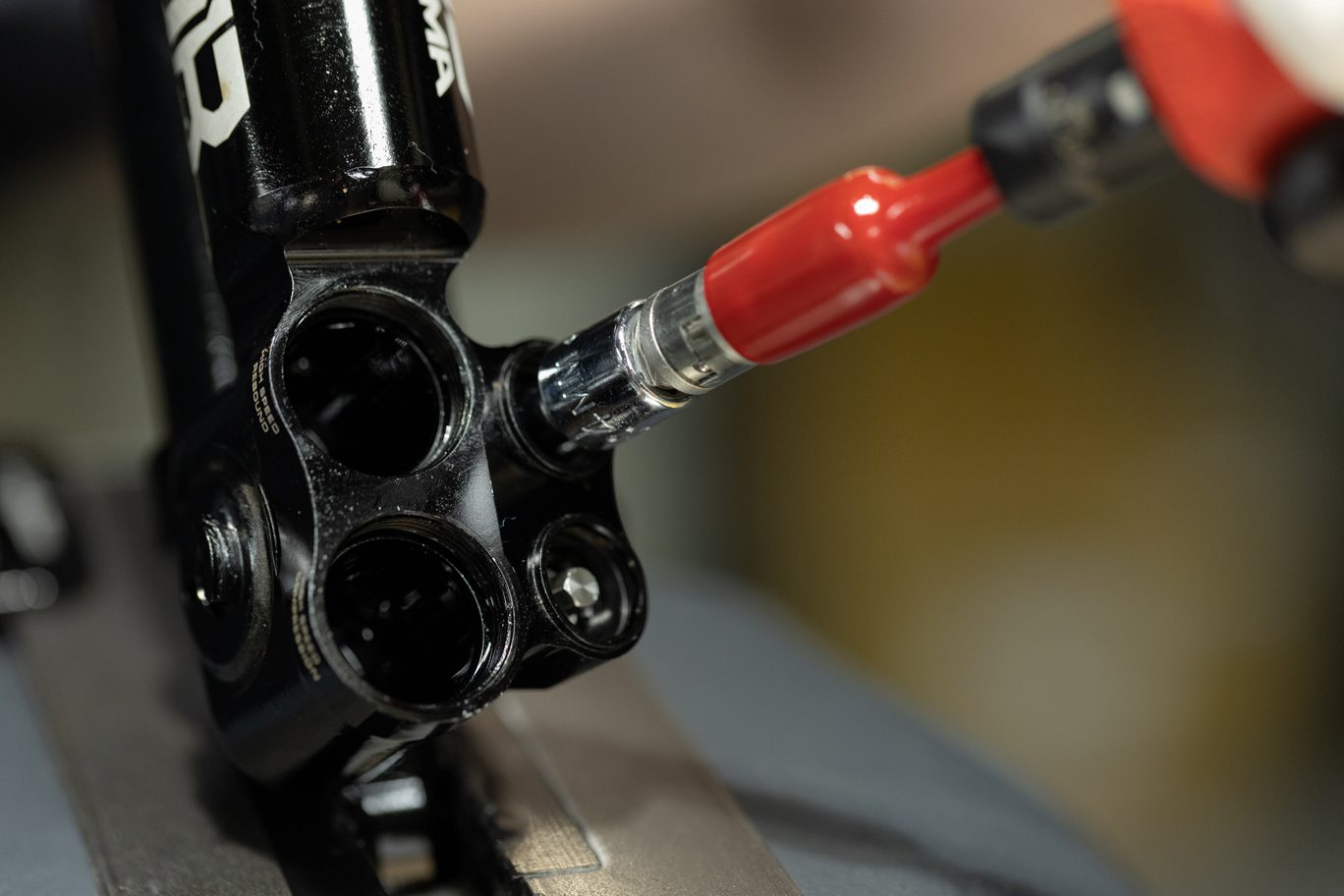
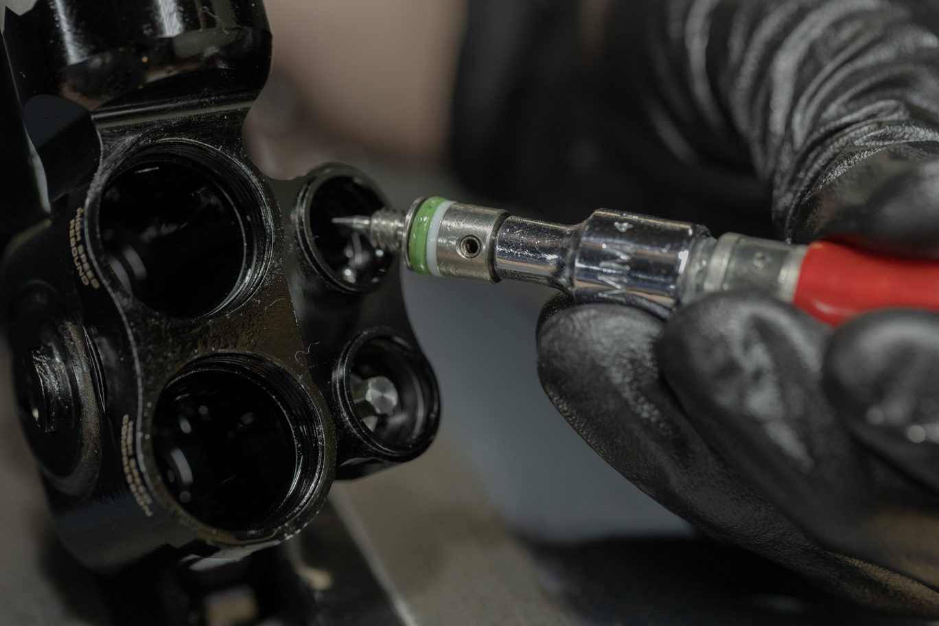
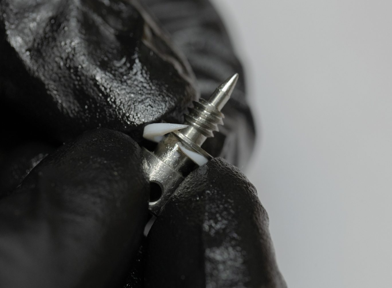
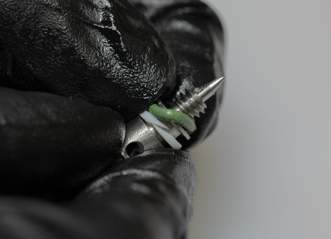
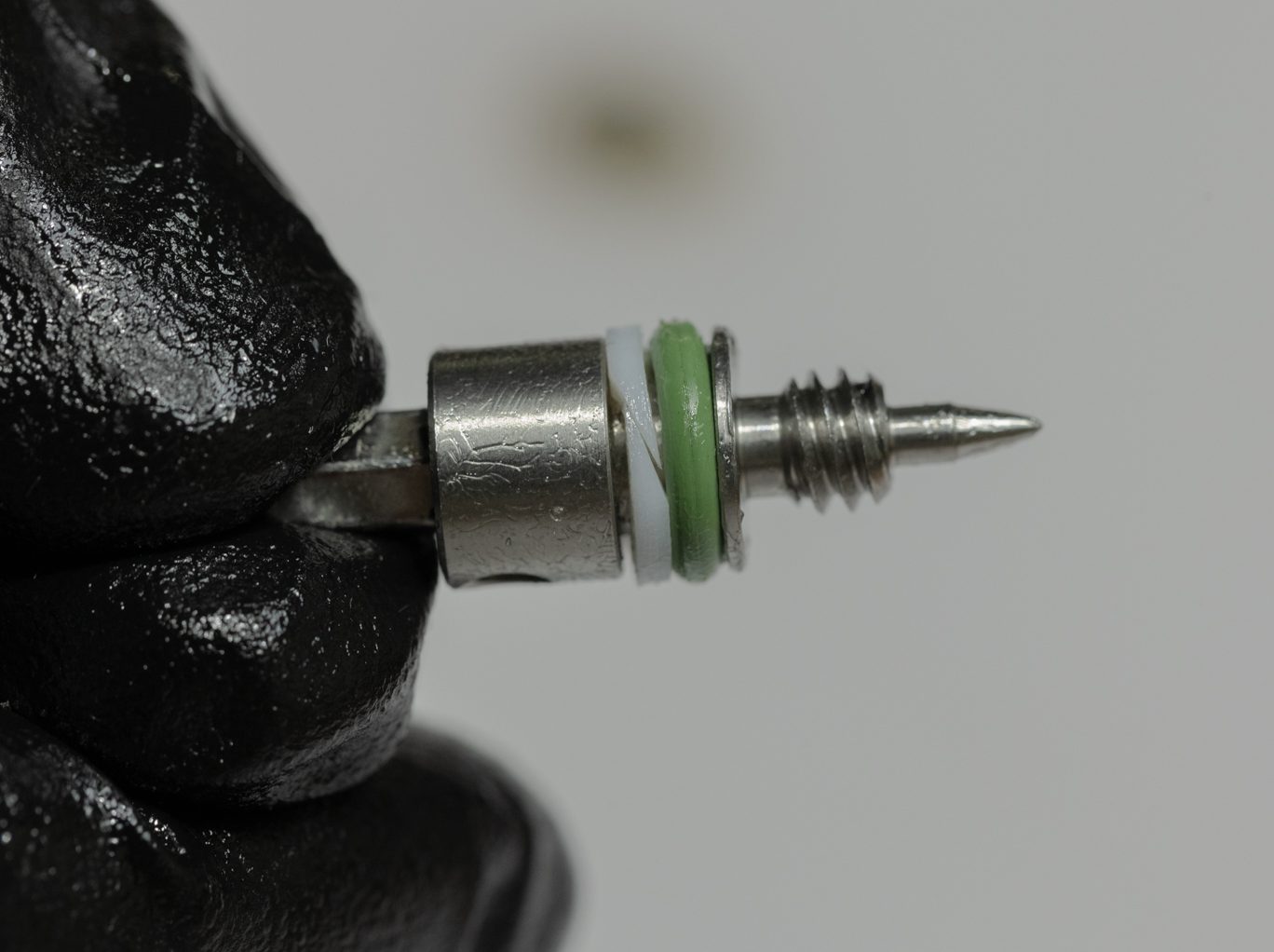
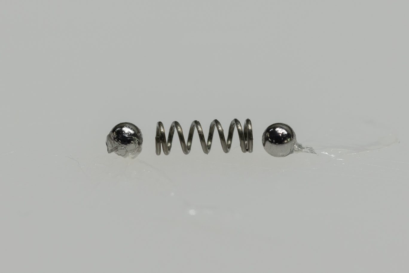
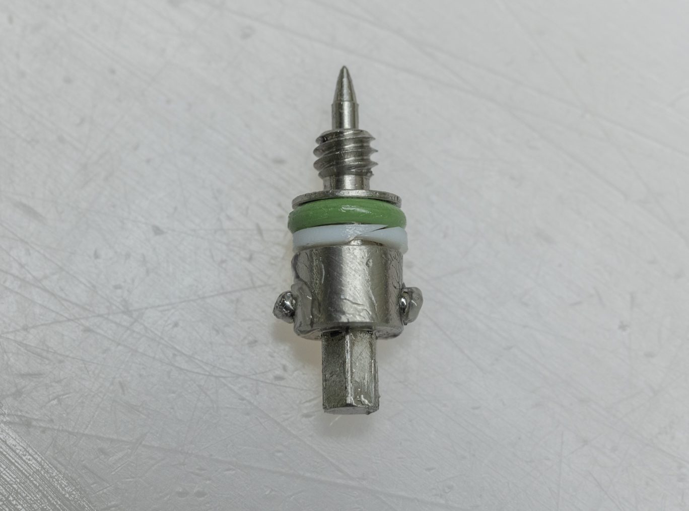
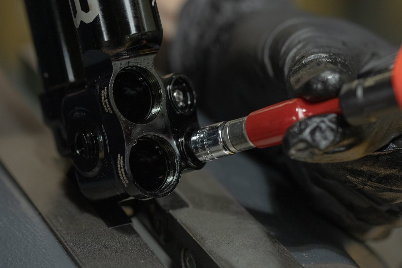
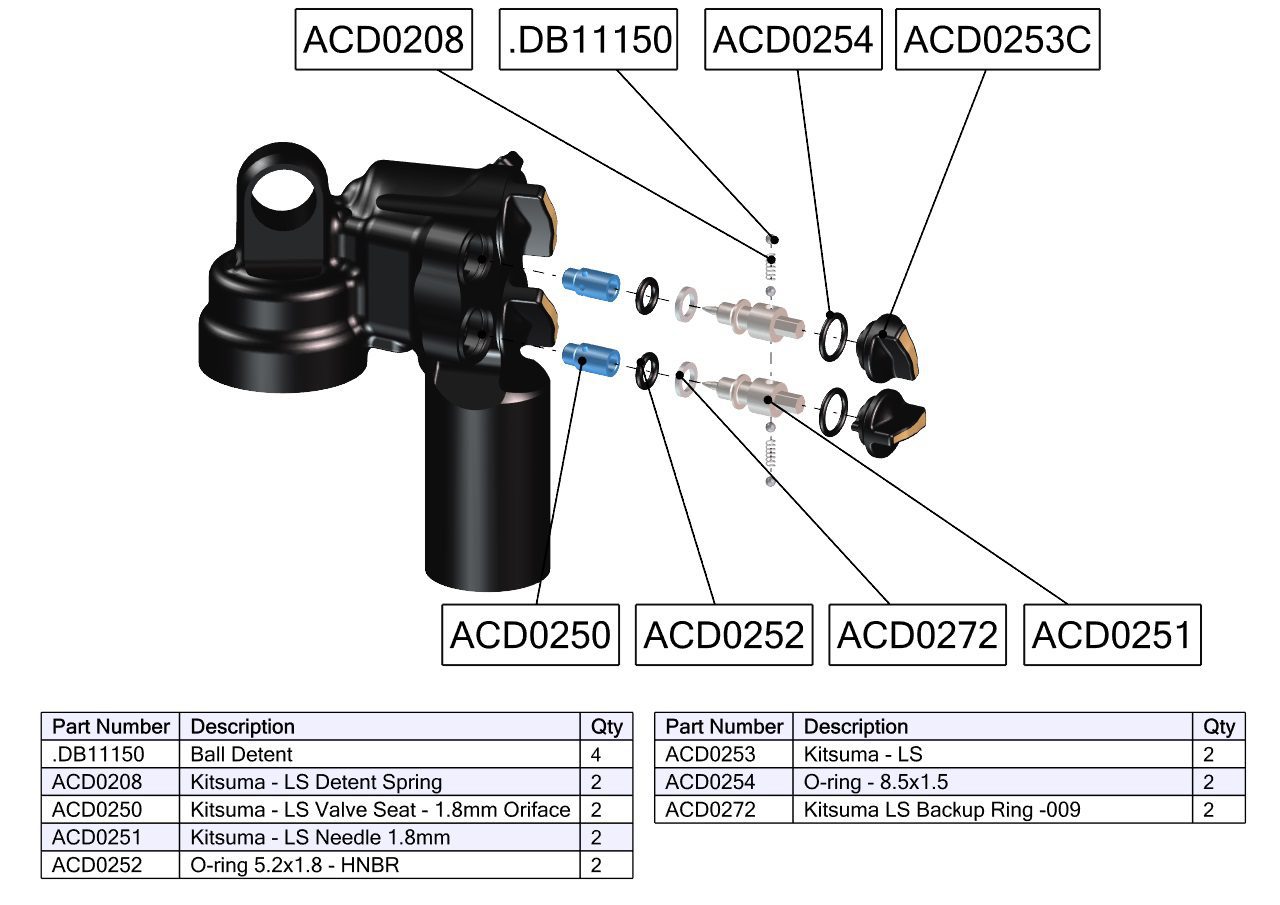
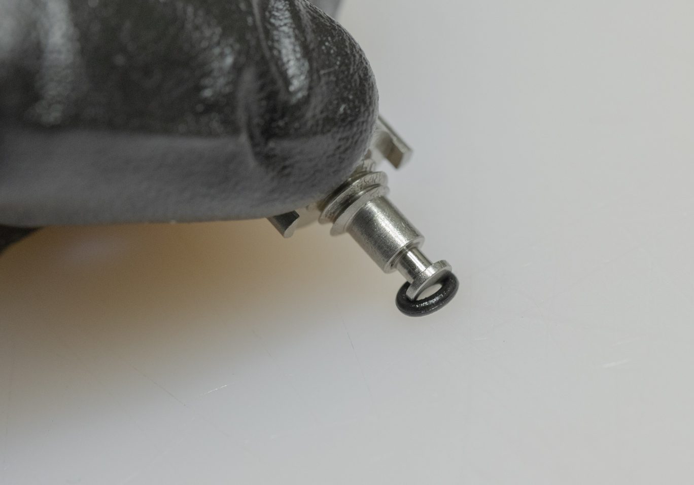
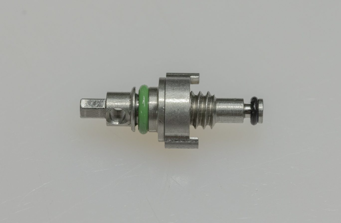
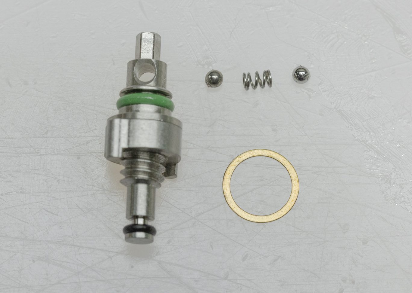
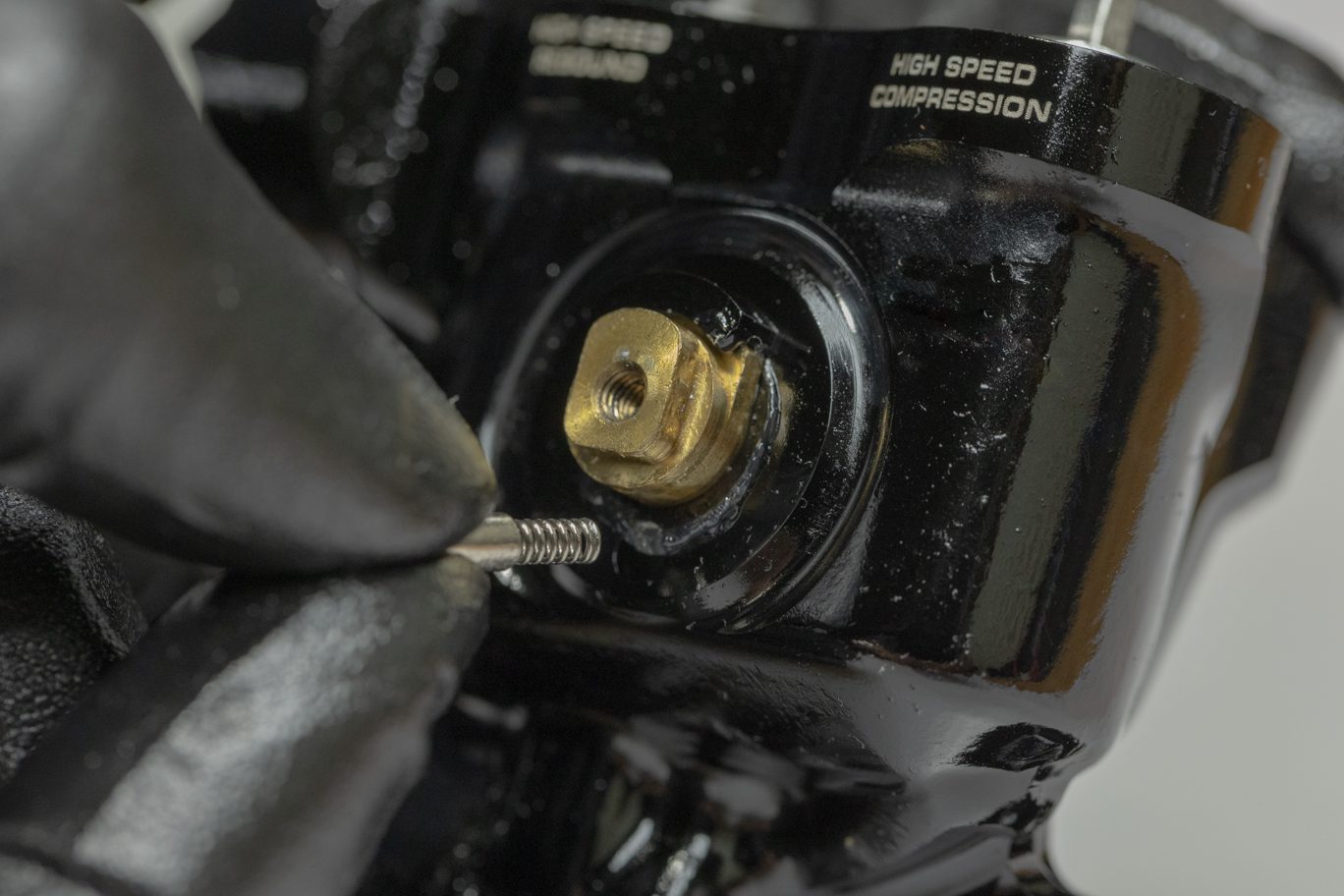
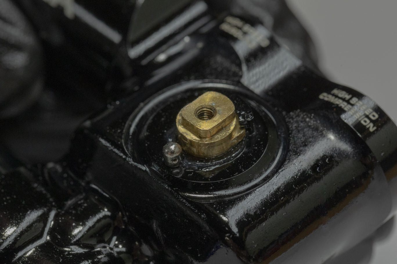
Install new back up ring (ACD0272) and lightly greased o-ring (ACD0252) on low speed needles. Using grease, reinstall spring and detent balls into low speed needles. Install low speed needles into valve body. Needle detent funnel (ACD0322) maybe used to ease install. Thread until bottomed then back out to ensure detents engagement. Then lightly bottom out the needle again.
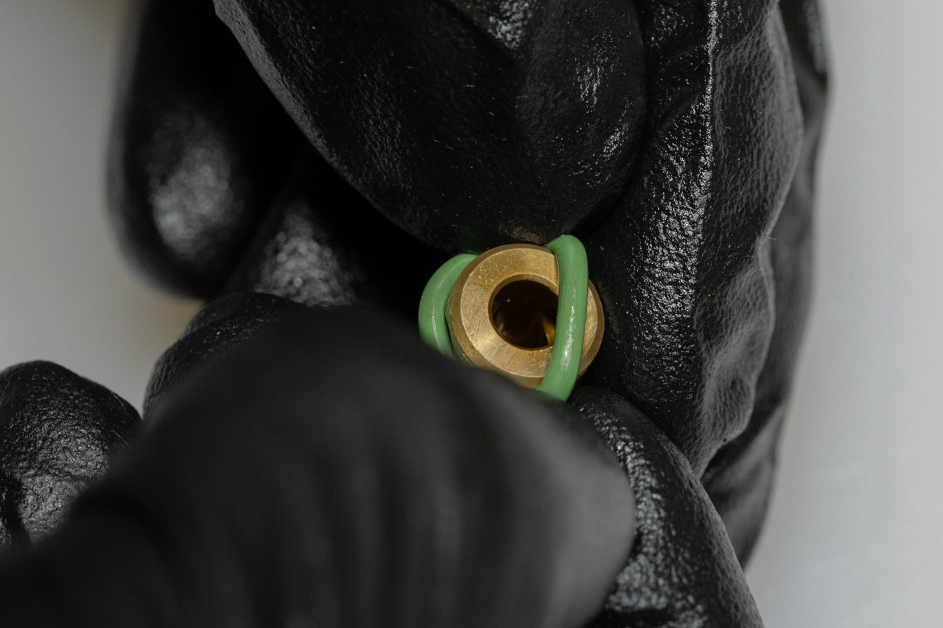
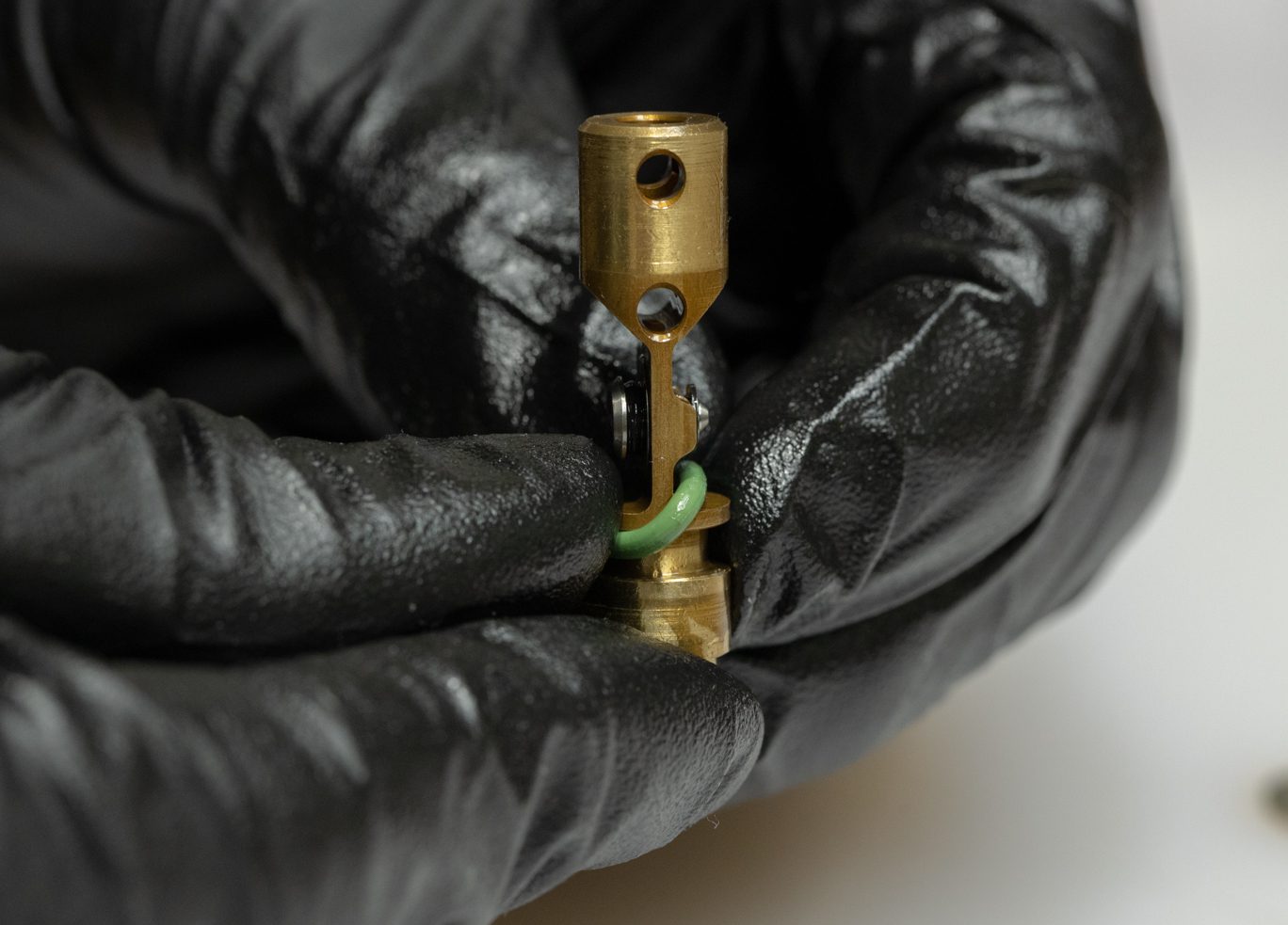
Thoroughly clean high speed adjustor threads and shuttle. Install shuttle onto adjustor. Note the orientation of the shuttle. Lightly grease and install high speed adjustor o-ring (ACD0265) and poppet o-ring (ACD0219).
TSB038 – Kitsuma HSR Revalve
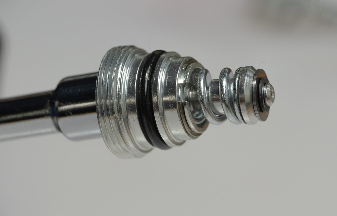
Insert gold shim into bottom of high speed adjustor housing. Using grease, reinstall spring and detent balls into high speed adjuster. Insert assembled high speed adjustors into high speed adjutor housing. Install circlip. Lightly grease and install high speed adjustor housing o-ring (ACD0212).
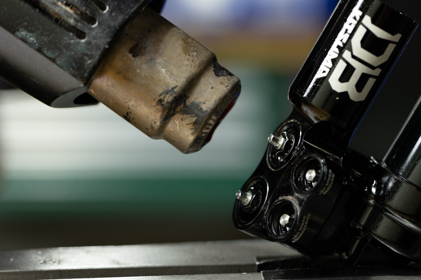
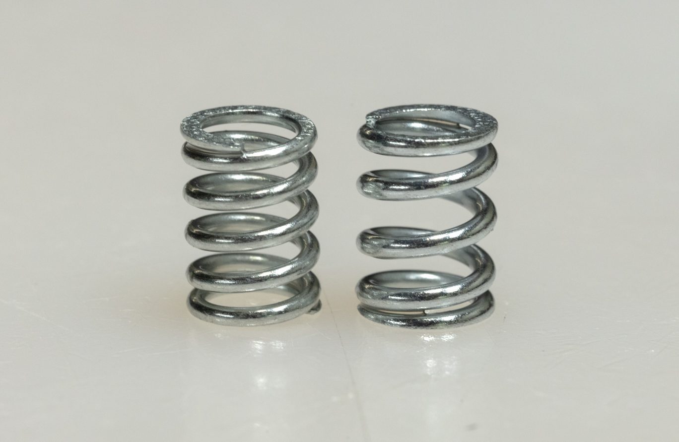
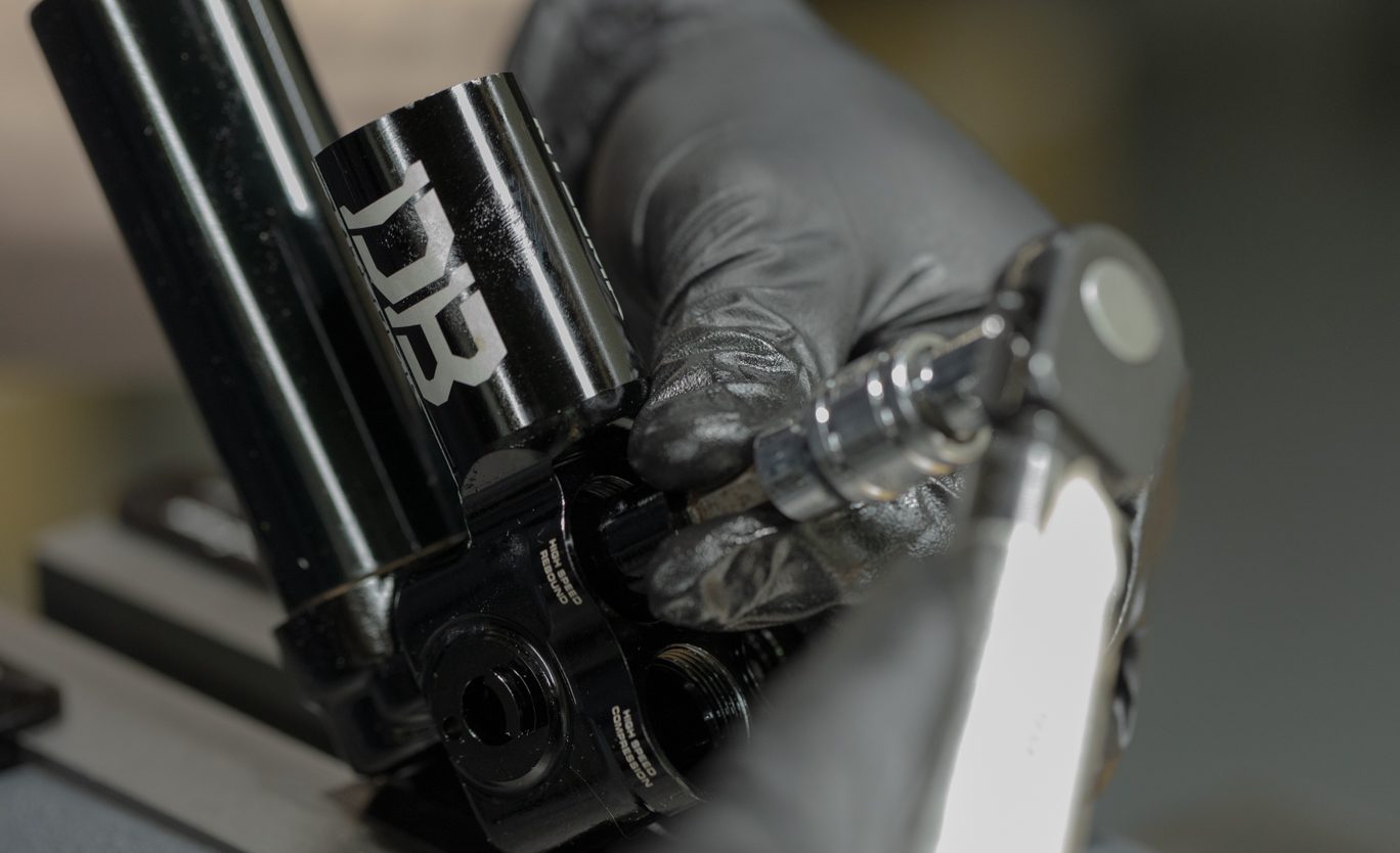
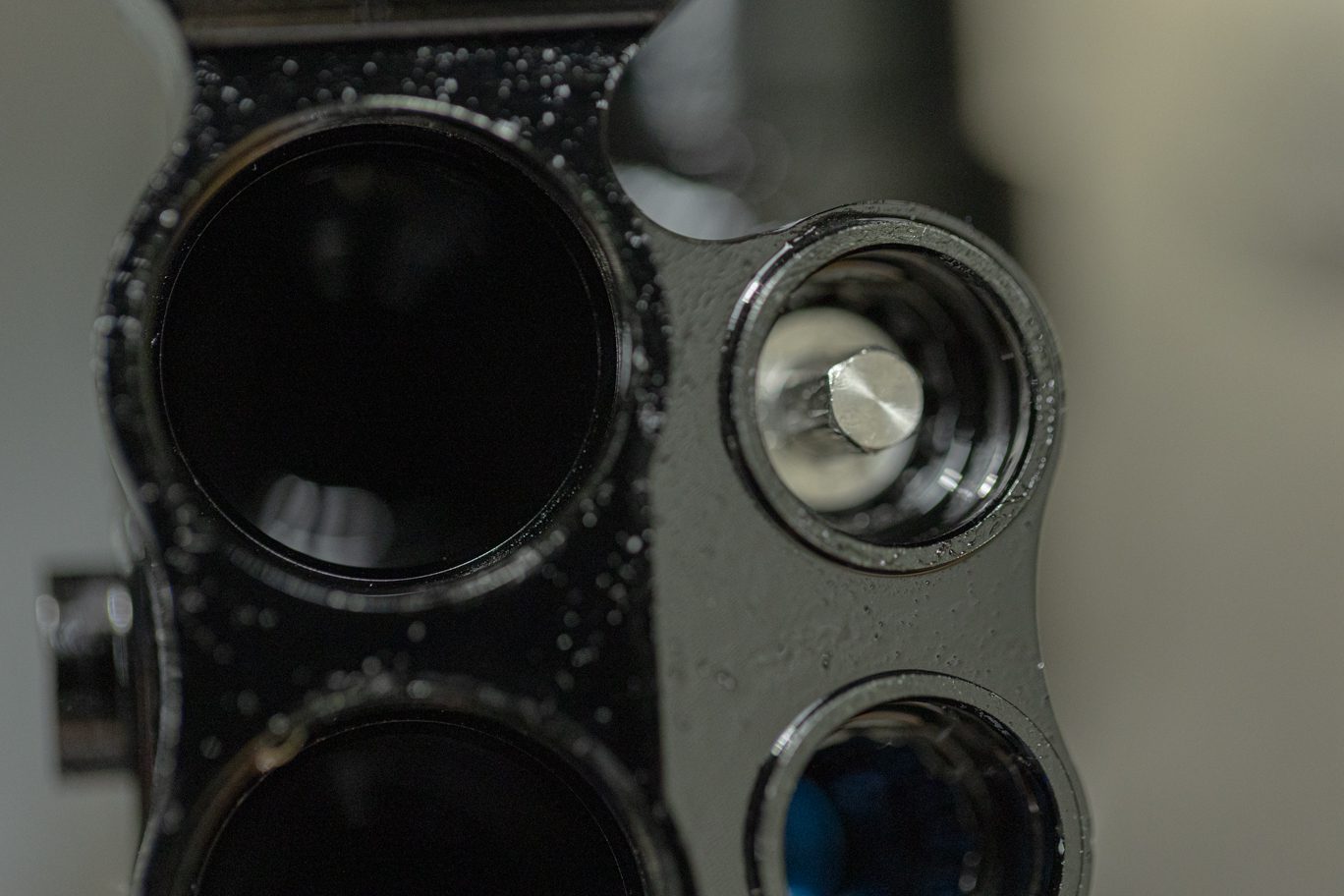
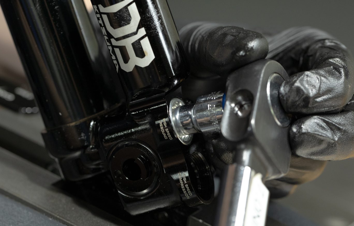
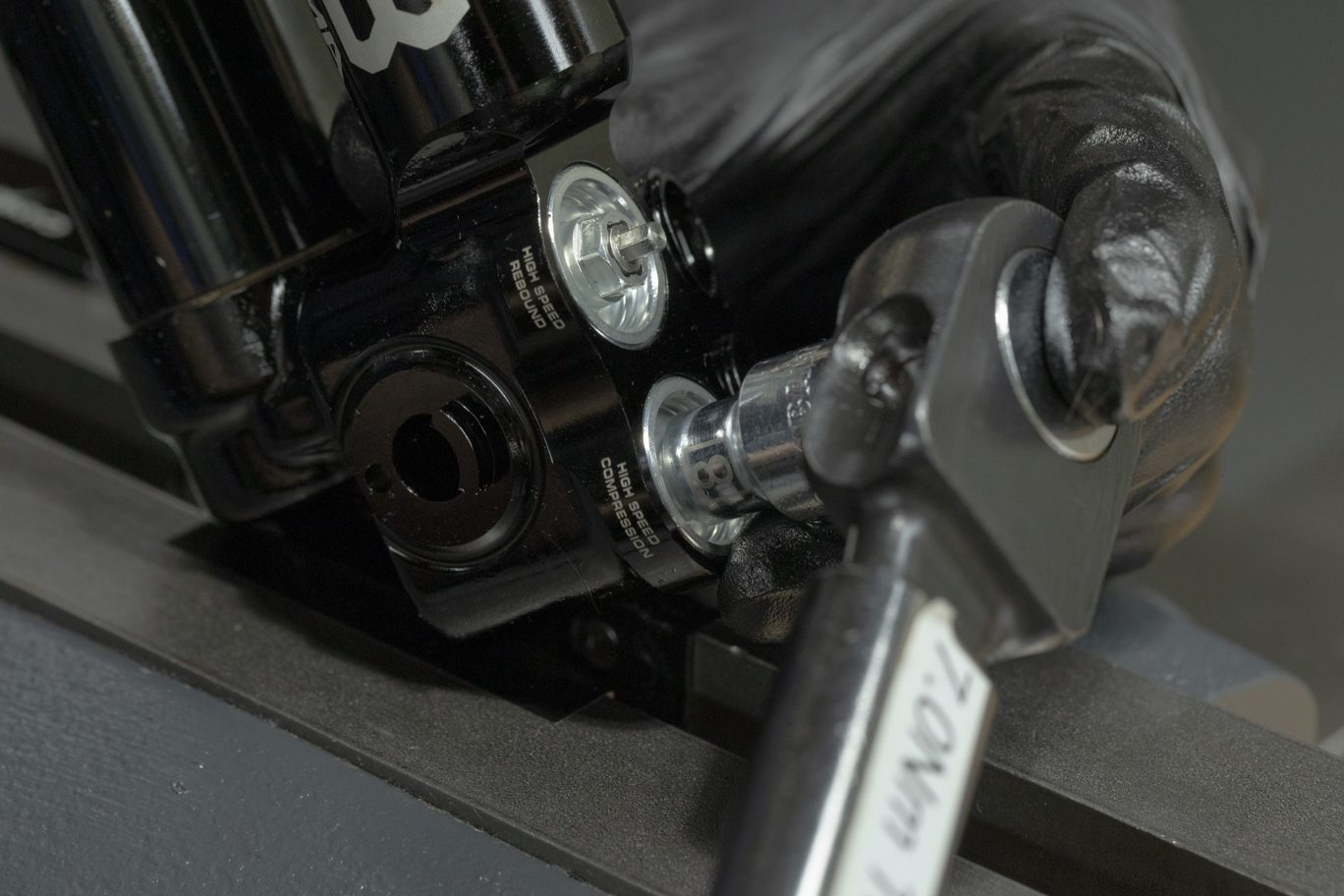
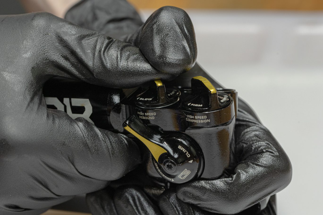
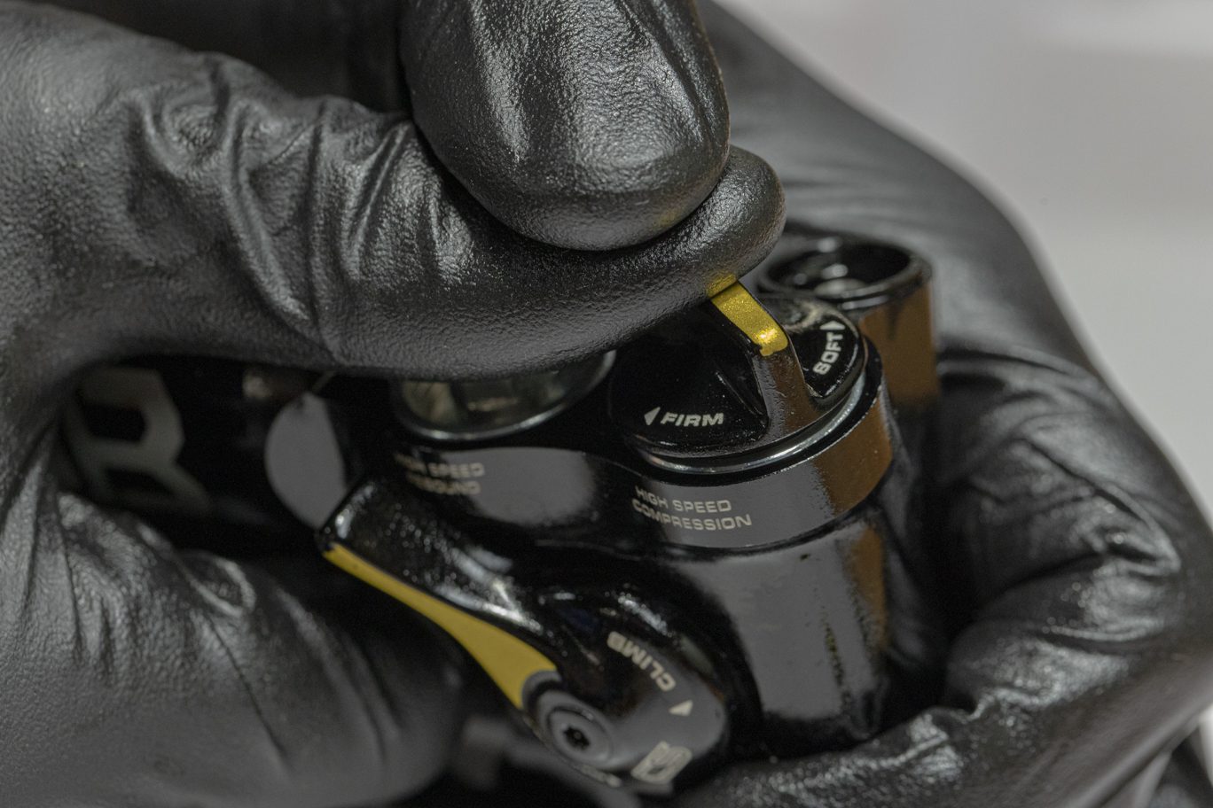
Install poppet assembly with shims towards valve body followed by poppet spring. Note rebound gets the stronger (40w) poppet spring and has 3 shims on poppet; compression has lighter (20w) spring and 1 shim. Using an 8mm socket, torque to 7 Nm.
TSB039 – Kitsuma High Speed Cap (ACD0275) Loctite Removal from Installation
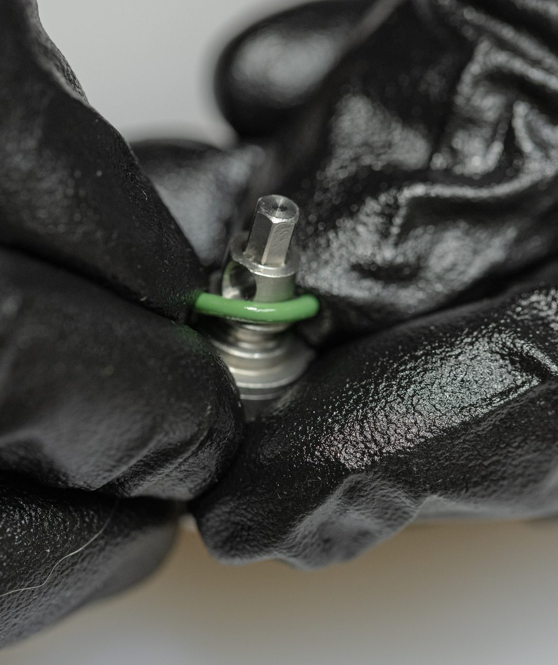
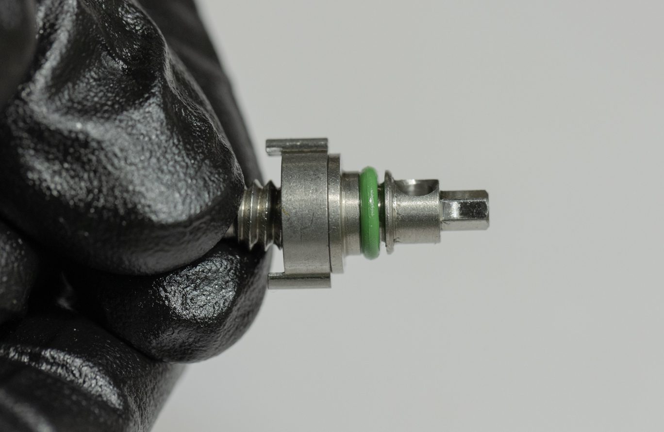
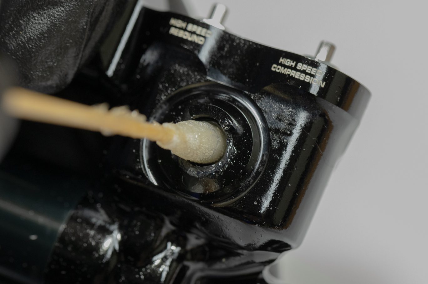
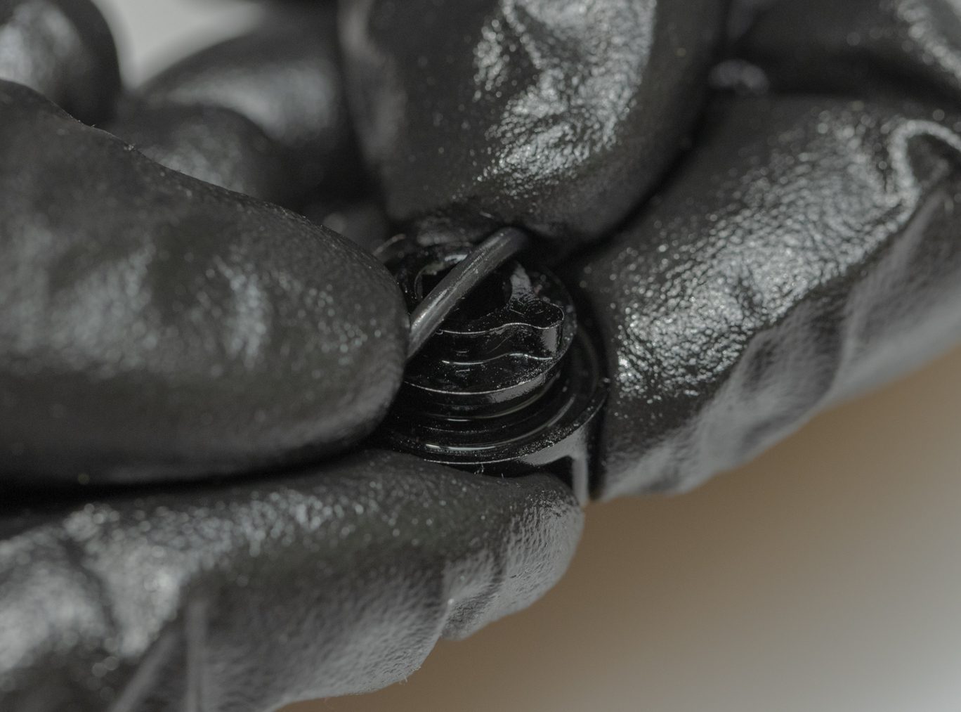
Light grease and install Climb Switch valve o-ring (ACD0266). IL CS bullet (AAD1454) can be used here. Apply grease to Climb Switch valve on valve body and to Climb Switch valve. Insert valve into valve body with tab at 3:00. Once engaged, rotate CS valve tab underneath valve body tab.
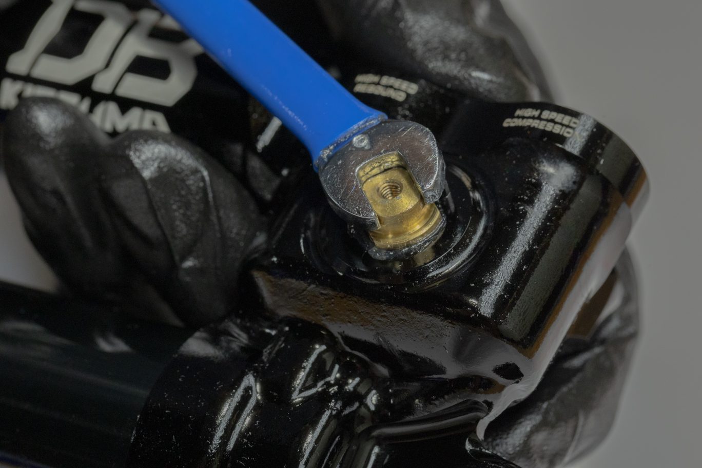
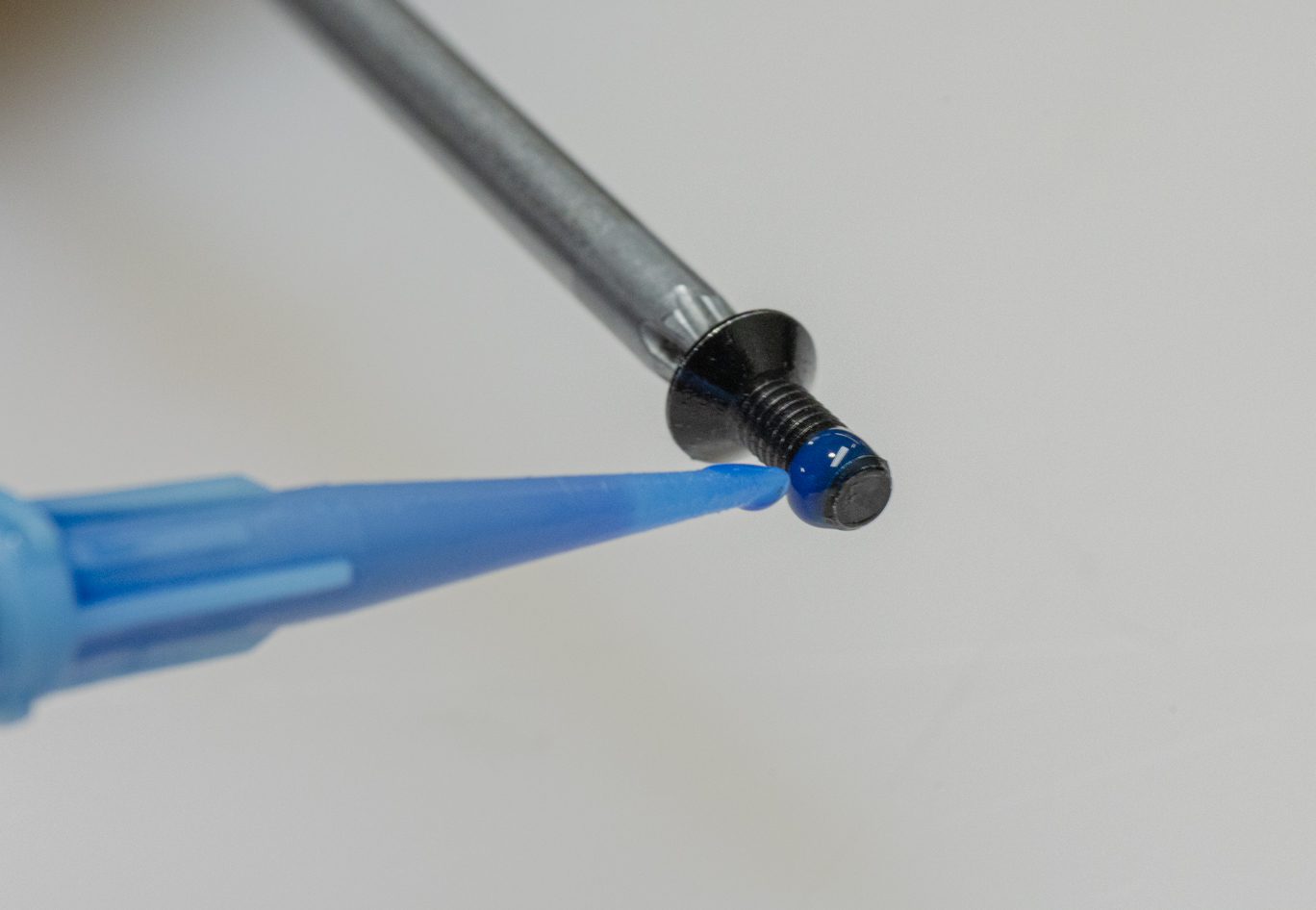
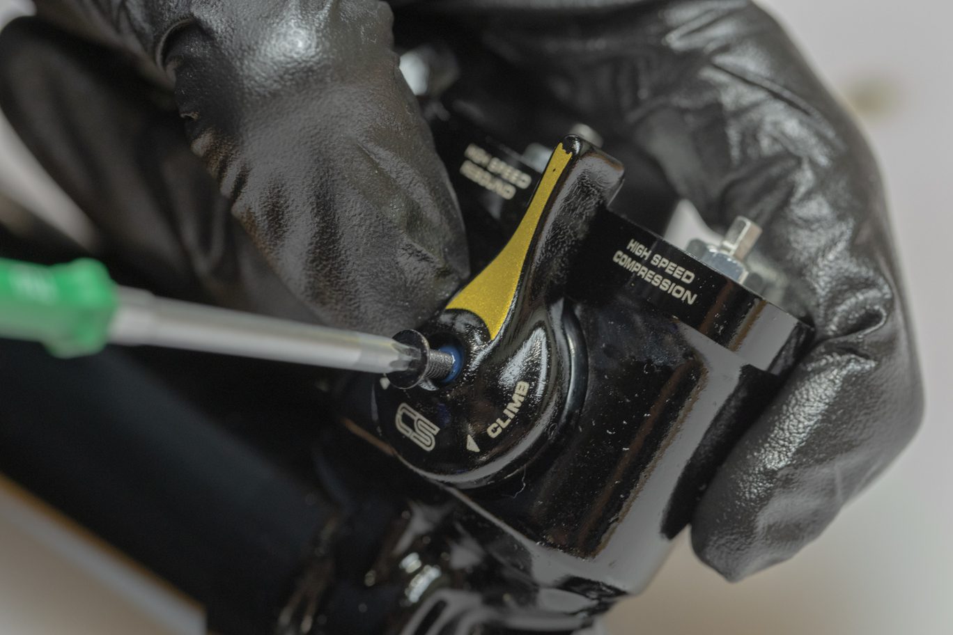
Light grease and install Climb Switch o-ring (AAD0800) on back side of lever. Place lever onto Climb Switch valve with lever at 9:00. Note that proper orientation of lever and valve required for proper interface. Apply blue Loctite (243) to Climb Switch mounting bolt. Secure CS lever with bolt. Torque to 1.2 Nm with T10.
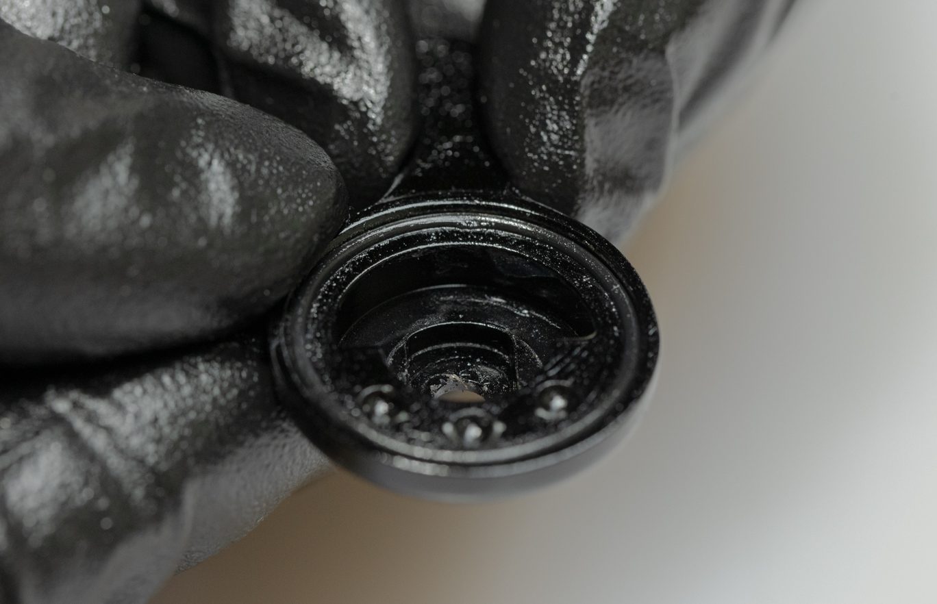
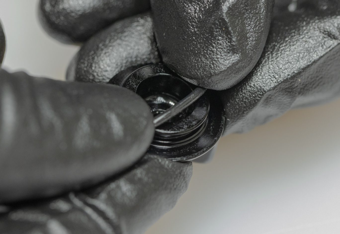
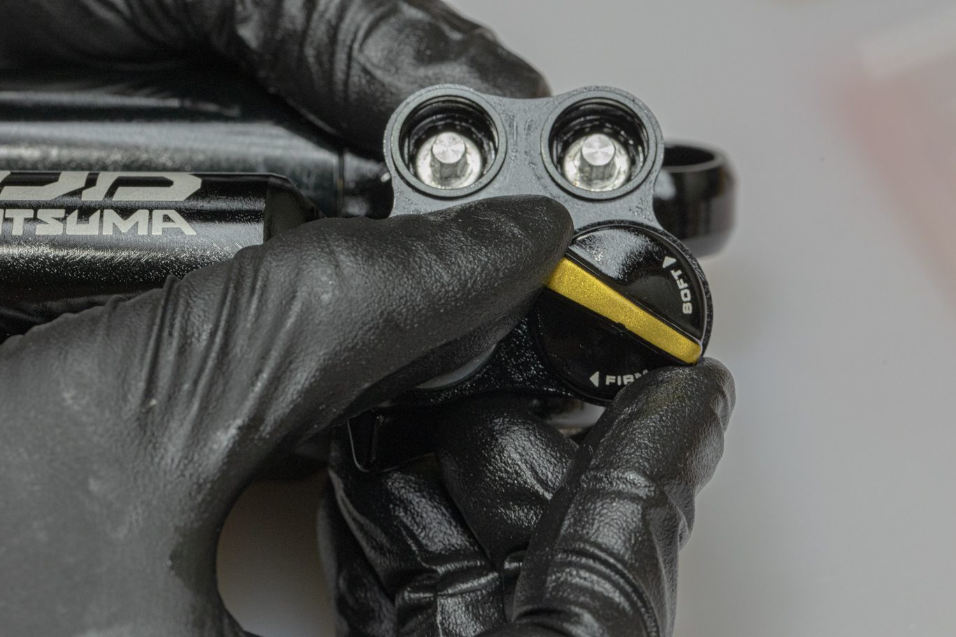
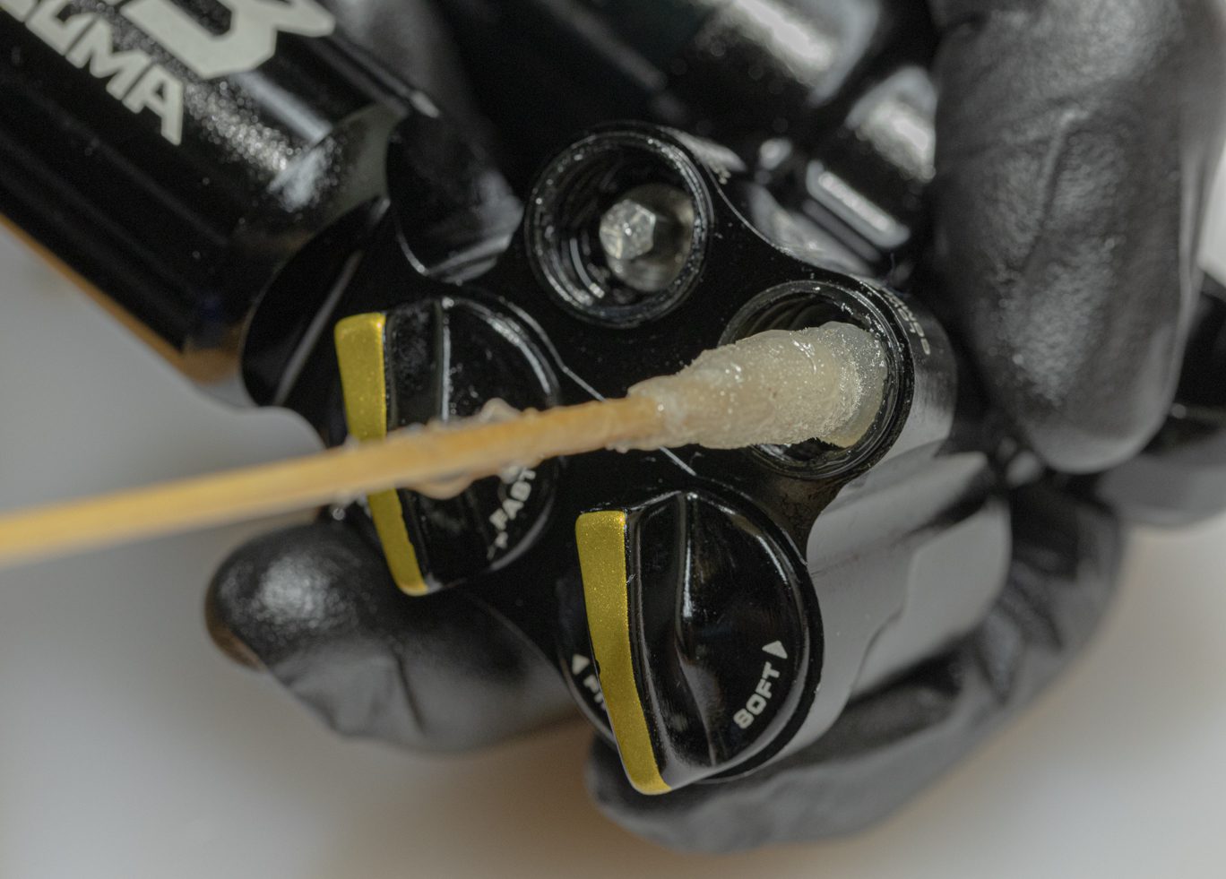
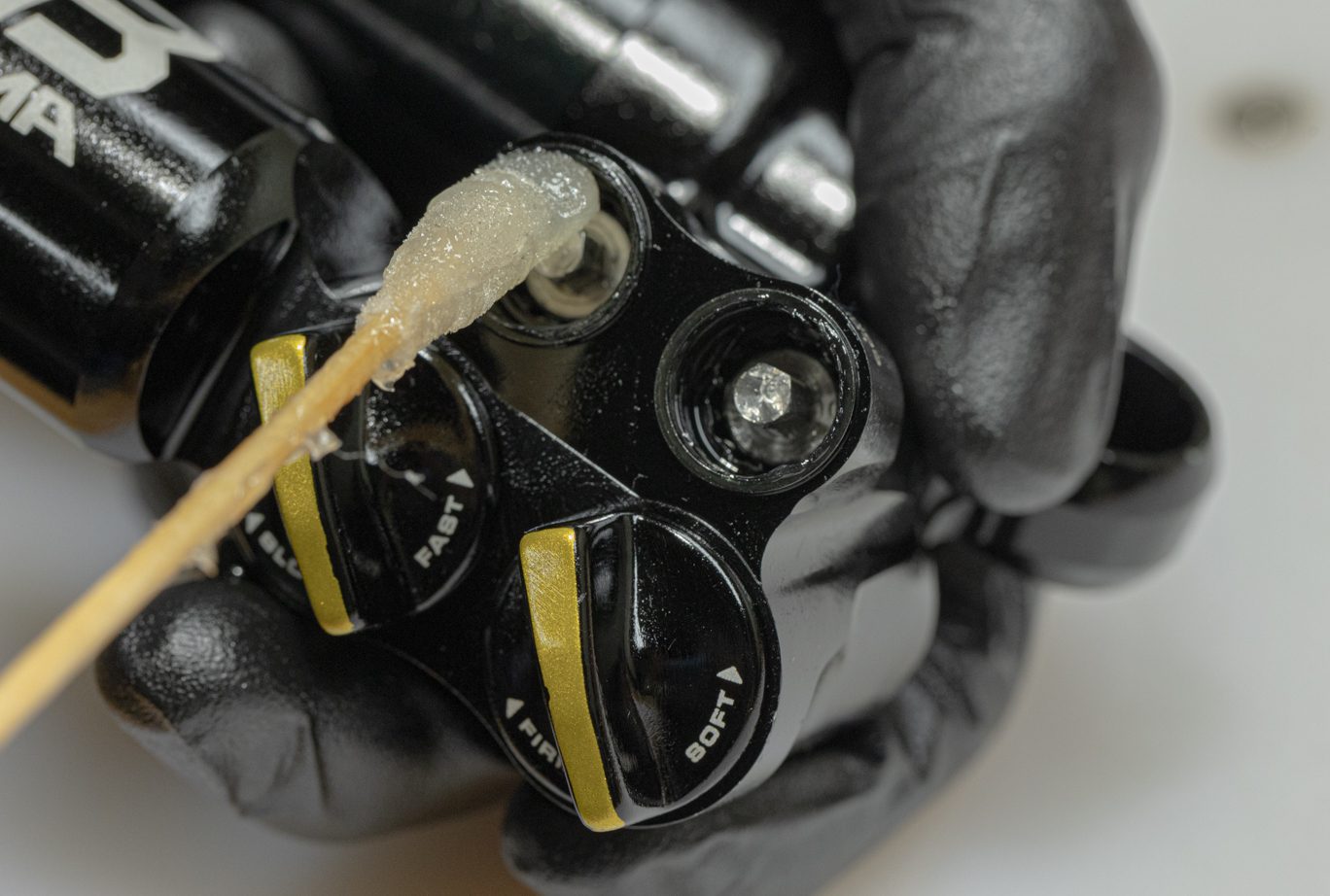
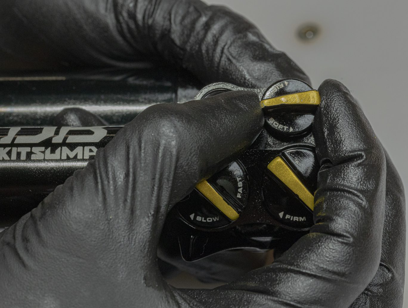
Lightly grease and install low speed adjustor dial o-rings (ACD0254) on back of dial. Apply thin layer of grease to the valve/dial interface on the valve body. Check that low speed controls are fully closed (clockwise). Line up dial at 6:00. Rotate dial and valve counterclockwise while applying gentle pressure until the dial seats onto the valve.
If updating from older IFP system, a new reservoir end cap (BCD0169) is required.
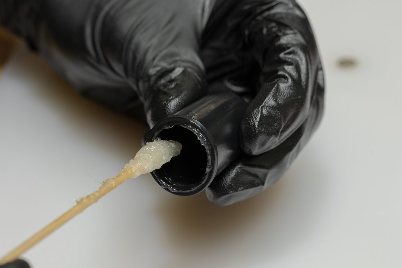
Grease all three sides of the quad ring portion of bladder.
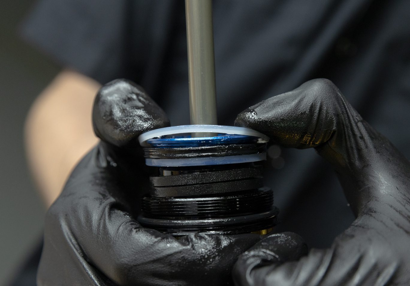
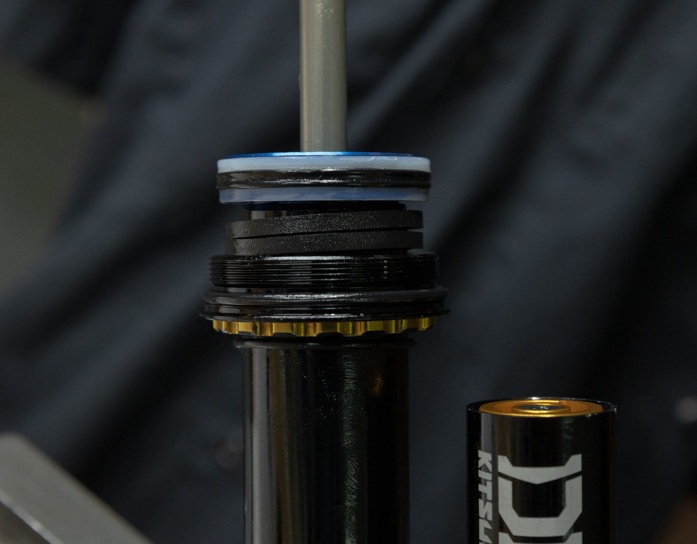
Work bladder onto reservoir cap. Insert end cap/bladder assembly into reservoir. Apply pressure to fully seat and expose circlip channel. Install circlip. Back end cap out against circlip using bladder fill tool or IFP setting tool.
TSB045 – Kitsuma IFP Changed to Bladder
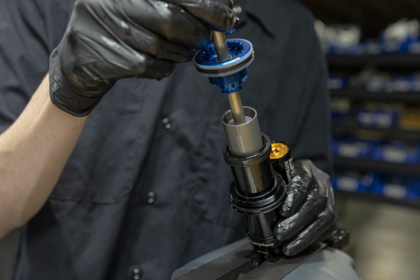
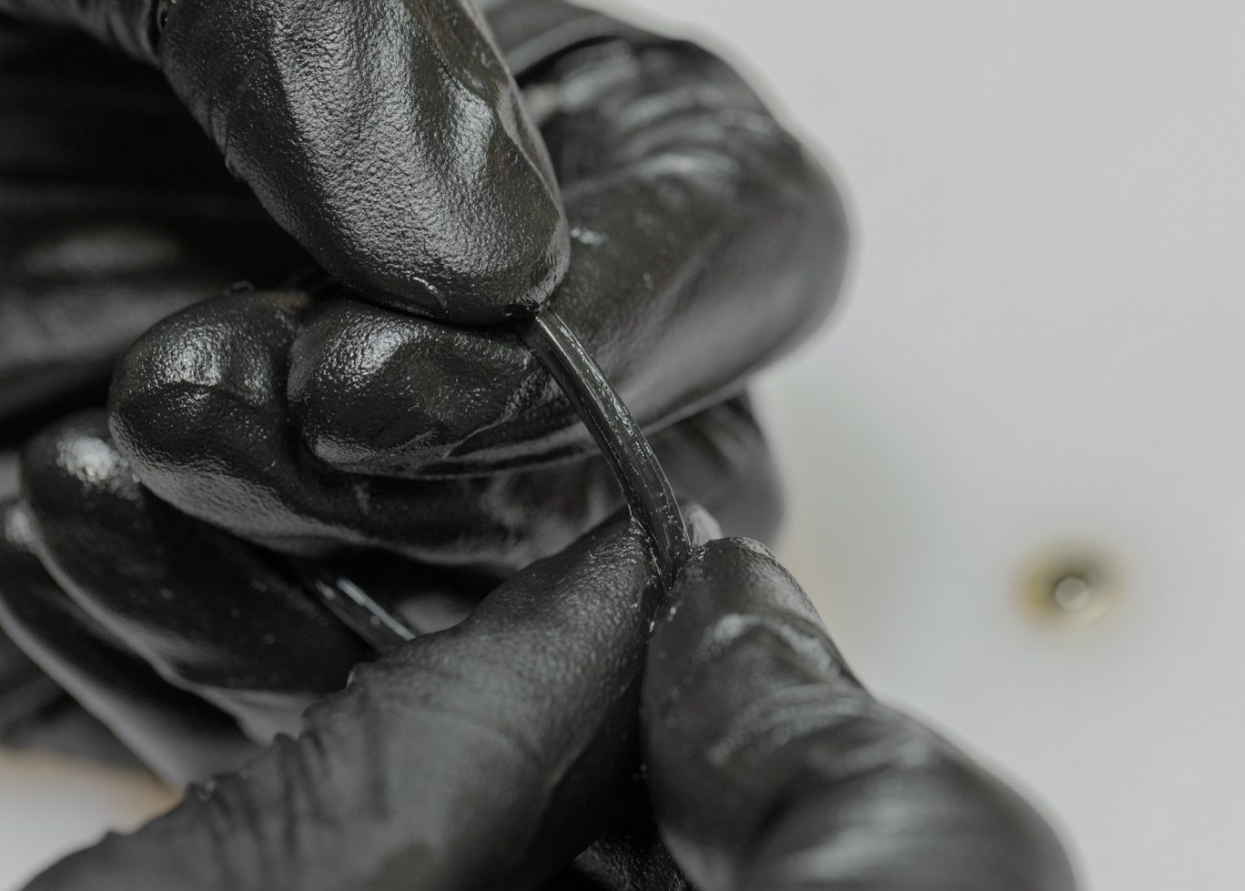
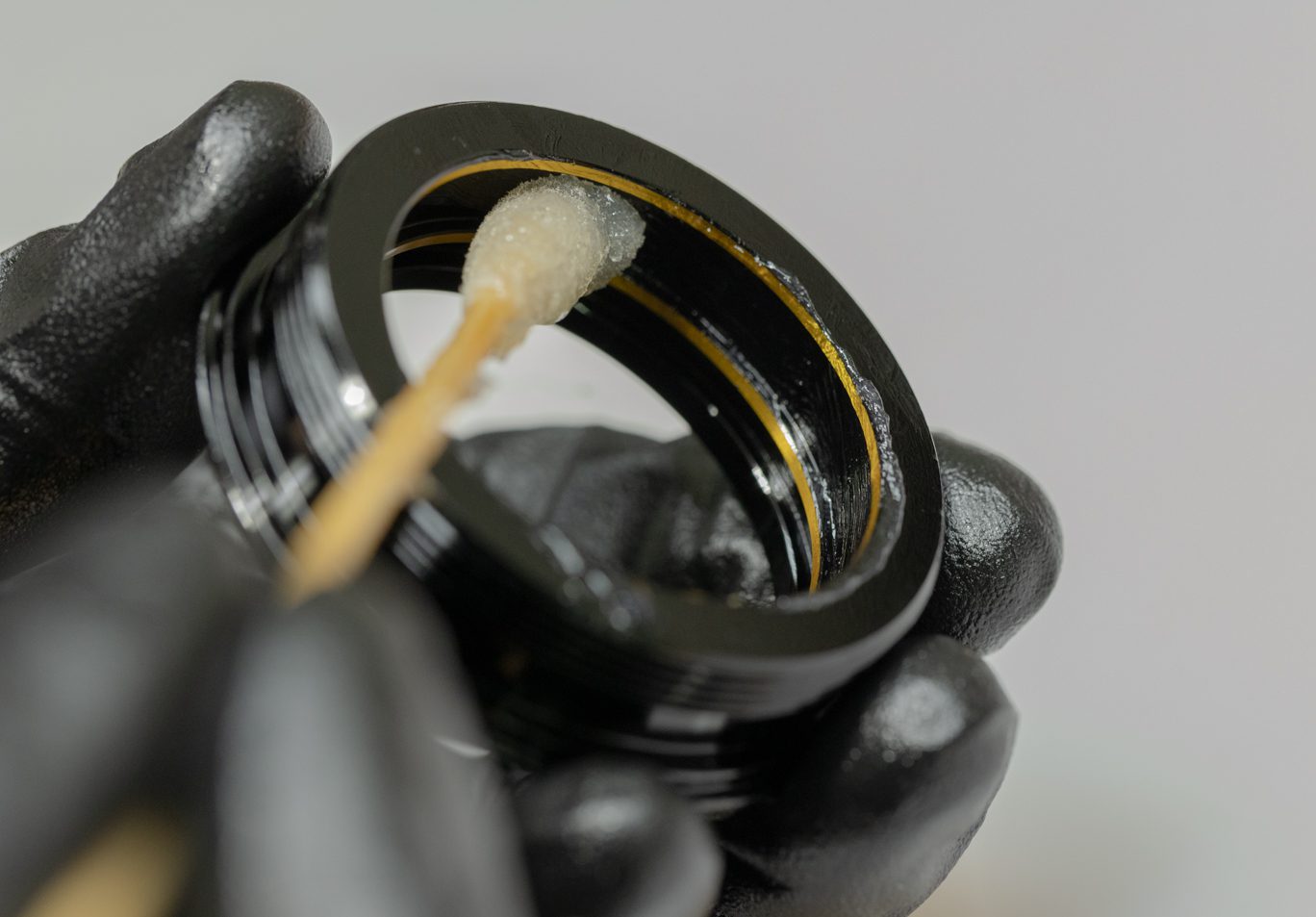
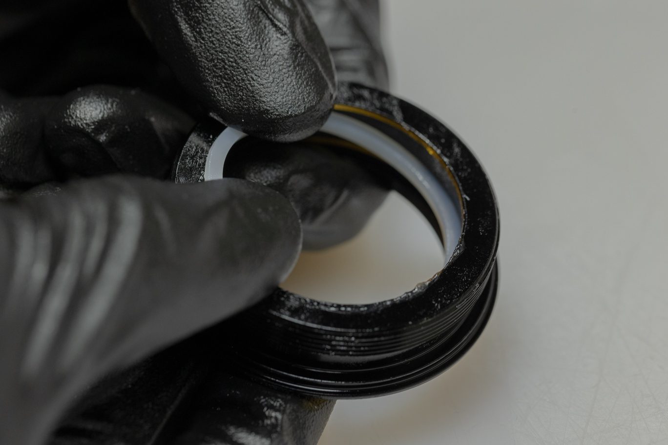
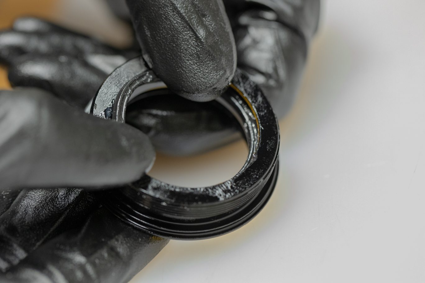
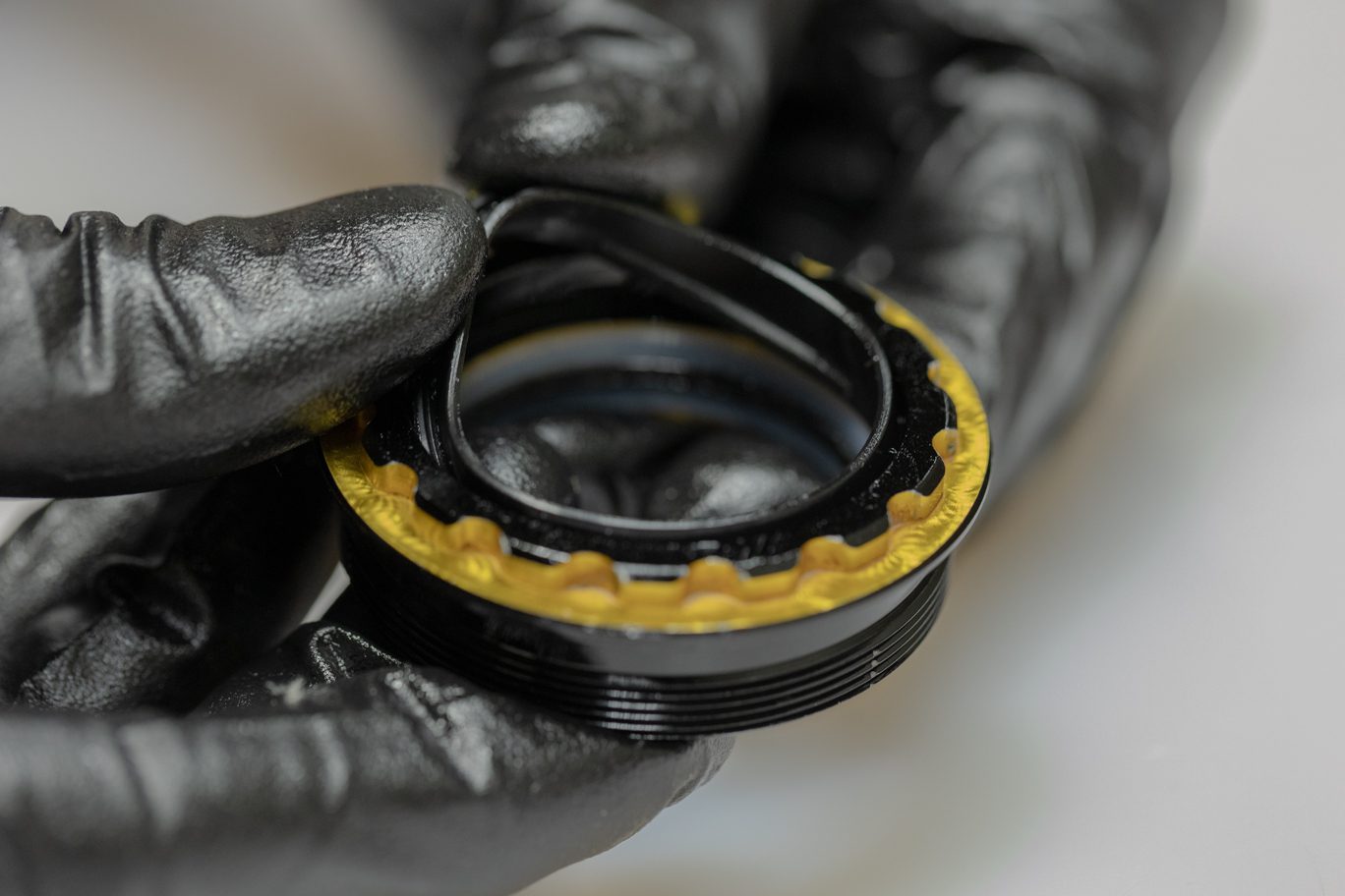
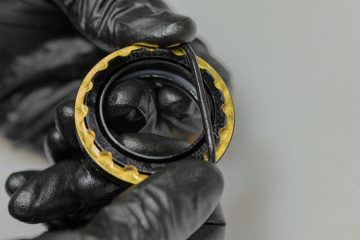
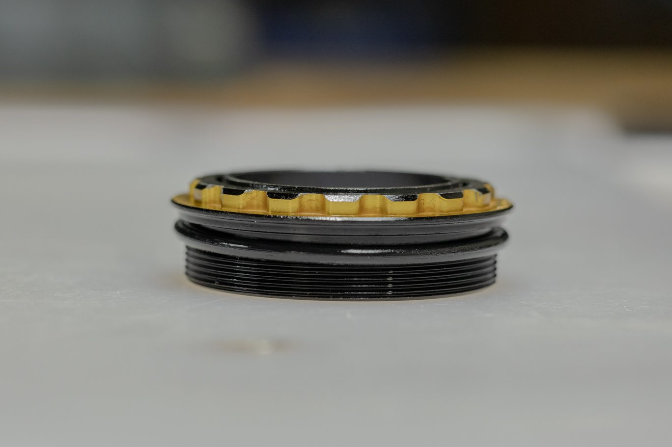
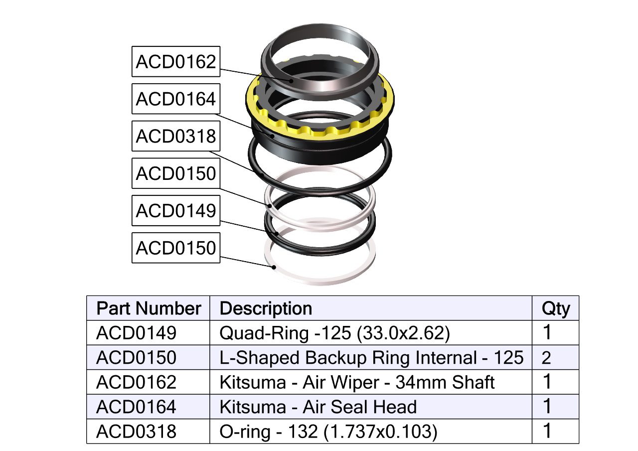
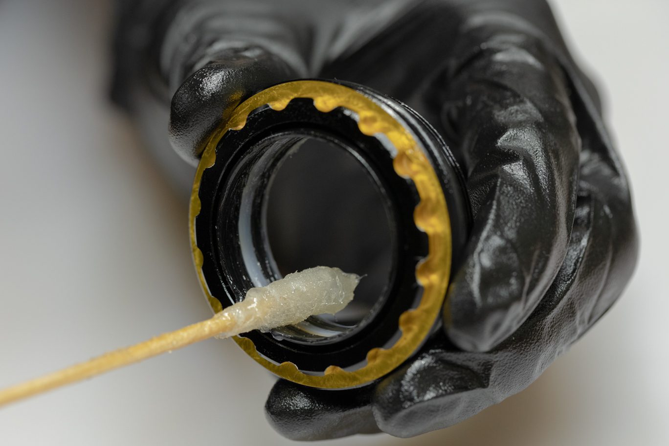
Thoroughly grease new air seal head quad ring (ACD0149) and quad ring channel on air seal head. Install new L-ring (ACD0150), quad ring and second L-ring with flat sides of L-rings towards quad ring. Install new dry wiper seal (ACD0162) into air seal head. Lightly grease and install new air seal head o-ring (ACD0318) on outside of air seal head.
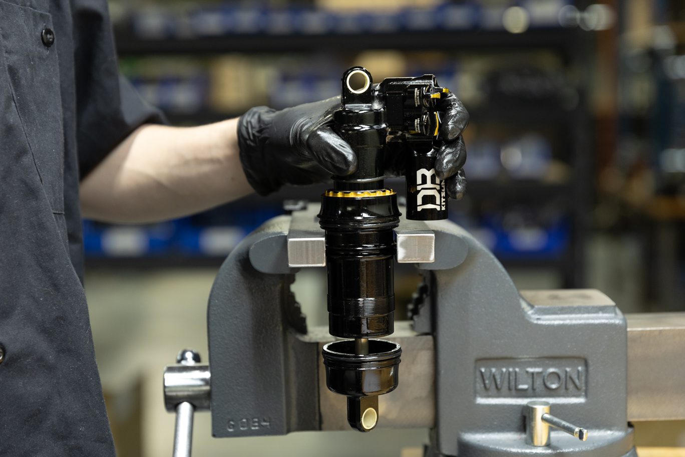
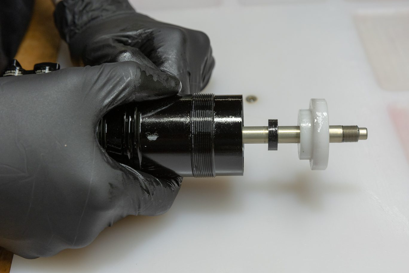
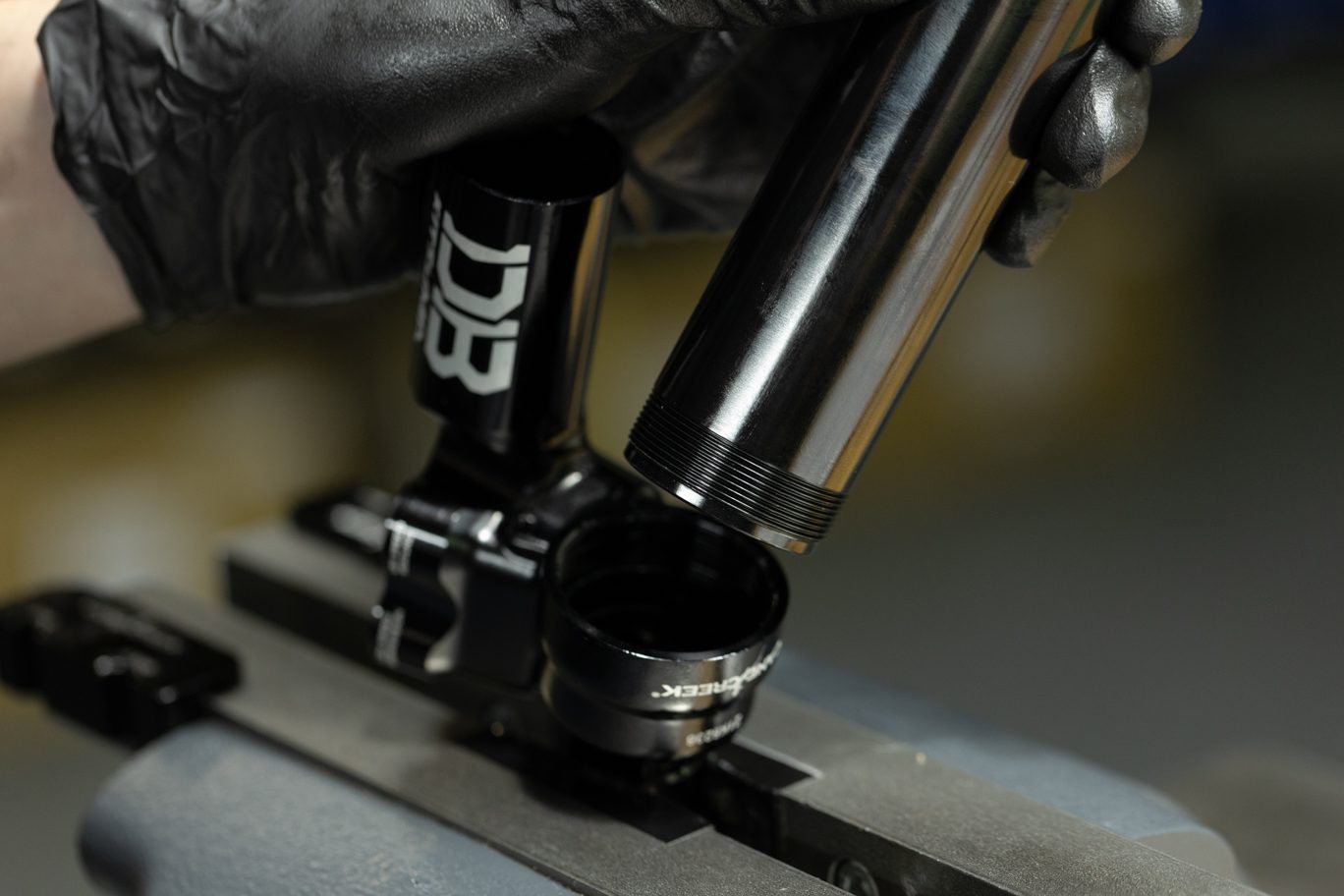
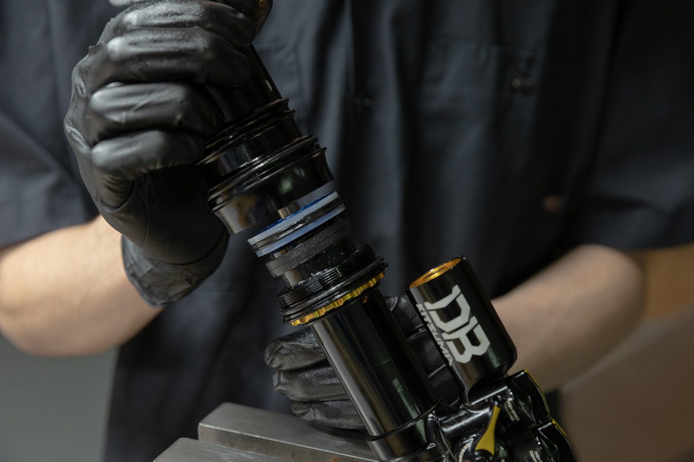
Apply grease to inside of completed air seal head assembly. Install new sag indicator o-ring (AAD0837) onto outer damper tube. Place air seal head on flat surface. With even pressure, insert damper tube into air seal head. Take care to not rock damper tube while installing to avoid rolling or cutting air seal head quad ring. Reinstall negative volume reduction bands if present.
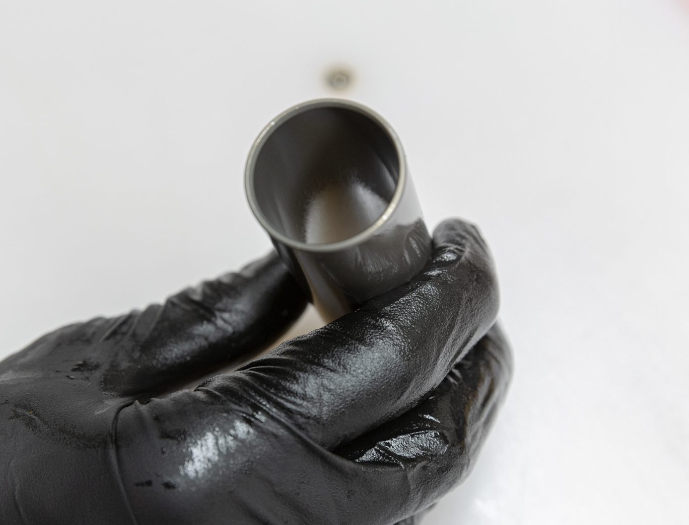
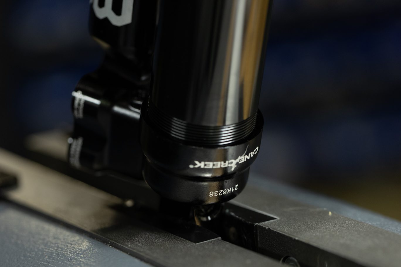
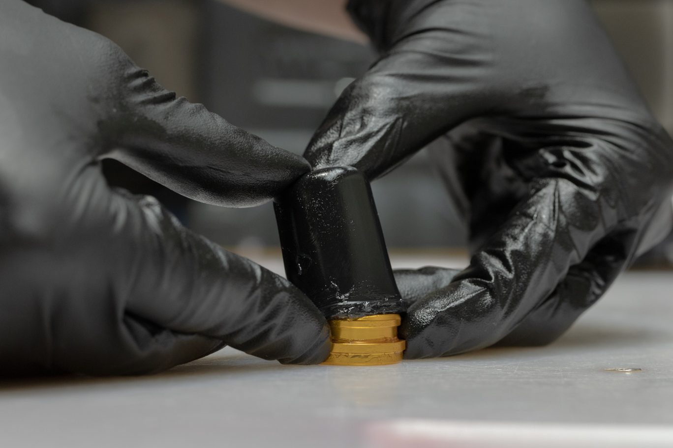
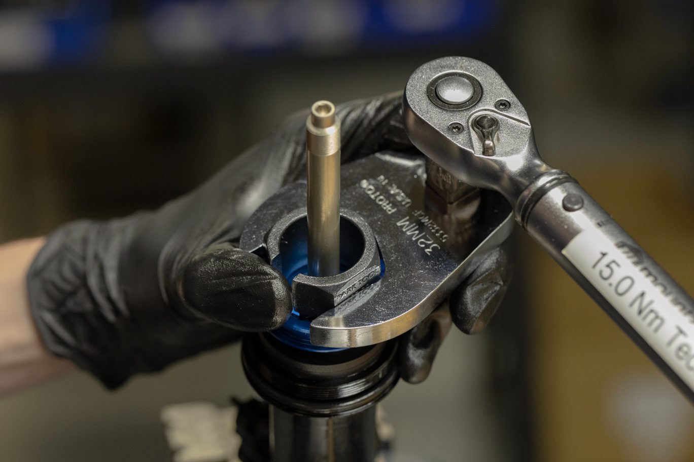
Coat piston band with shock oil. Work piston into inner damper tube. Insert inner damper tube/air oil seal head assembly into outer damper tube. Thread air oil seal head onto outer damper tube. Torque to 22 Nm with air oil seal head tool and 1/2″ crowsfoot.
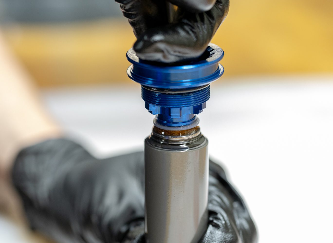
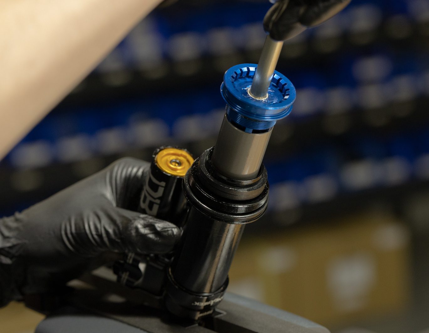
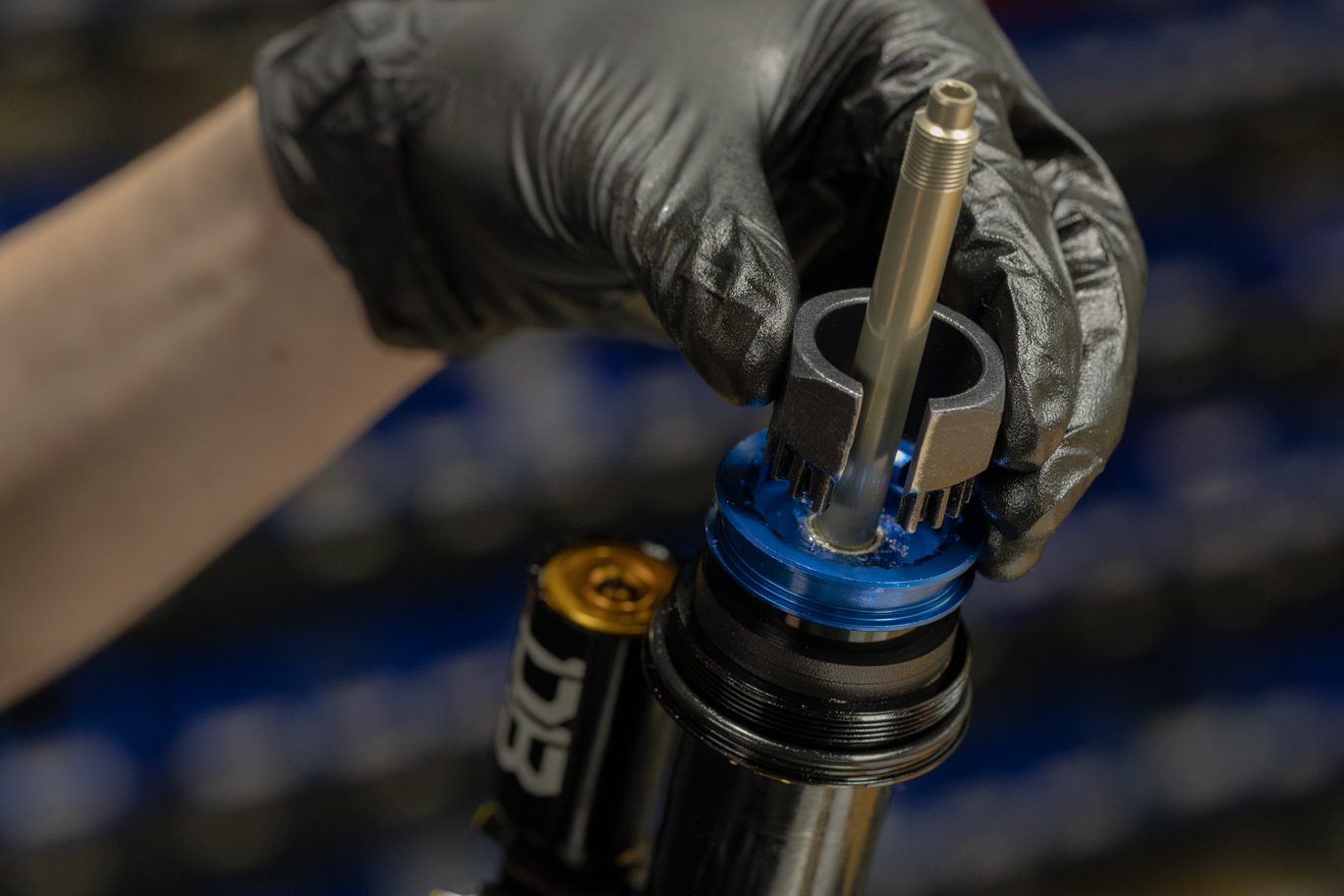
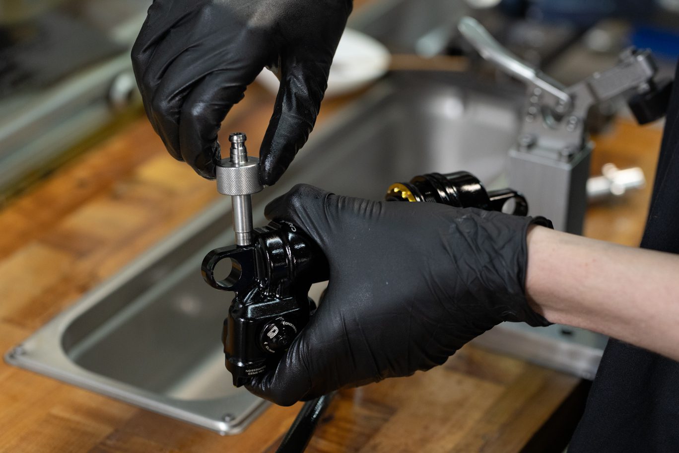
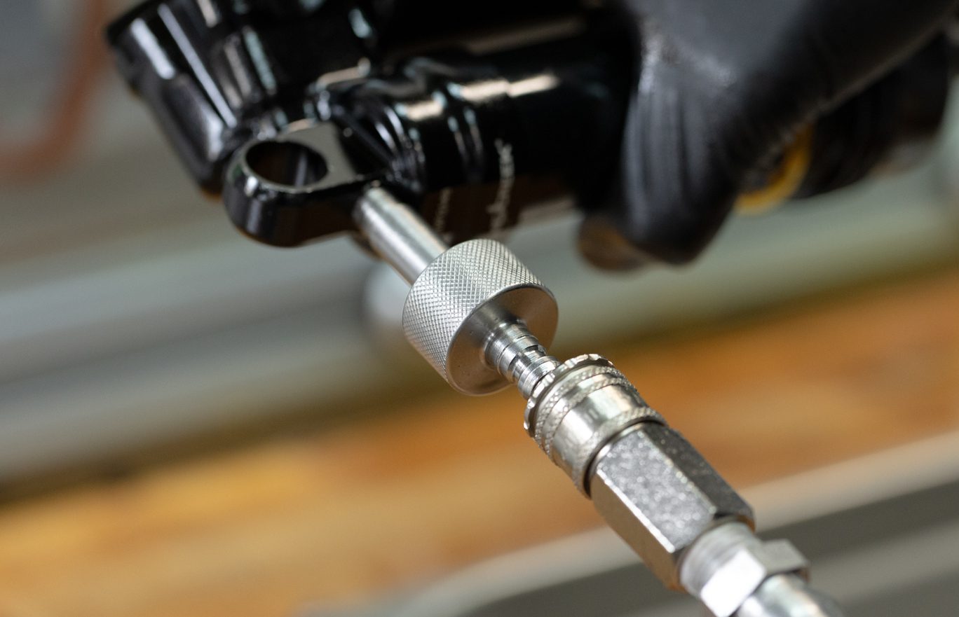
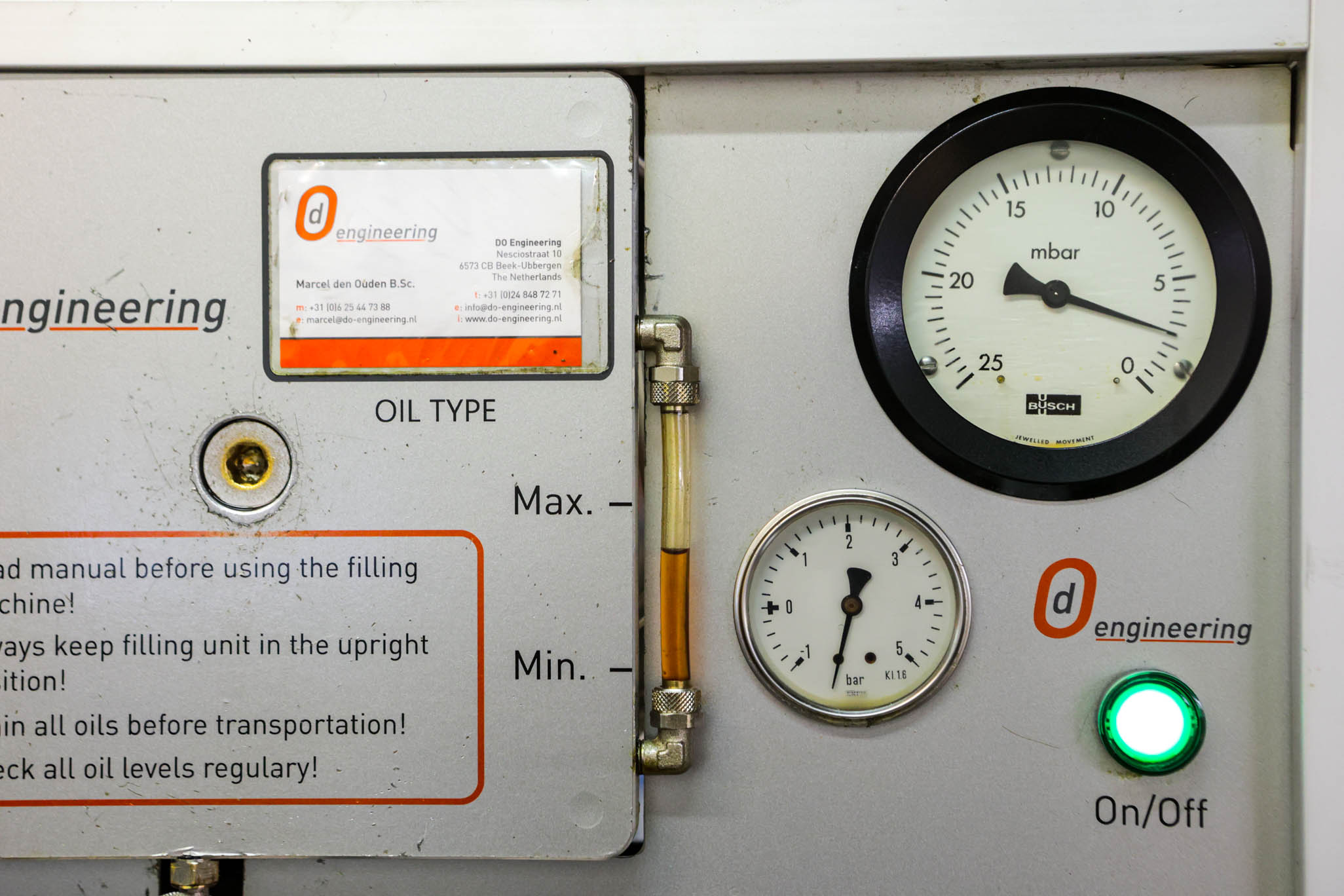
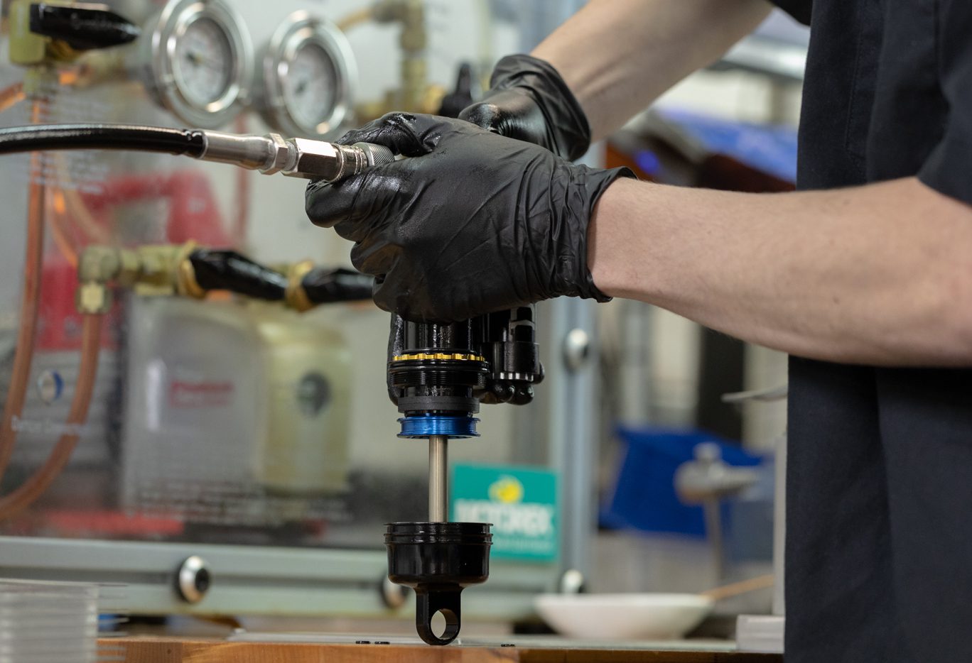
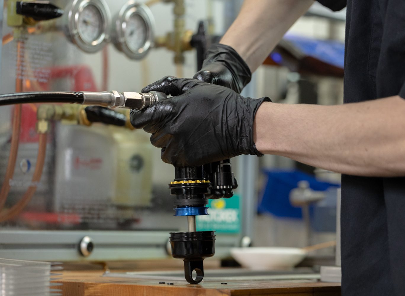
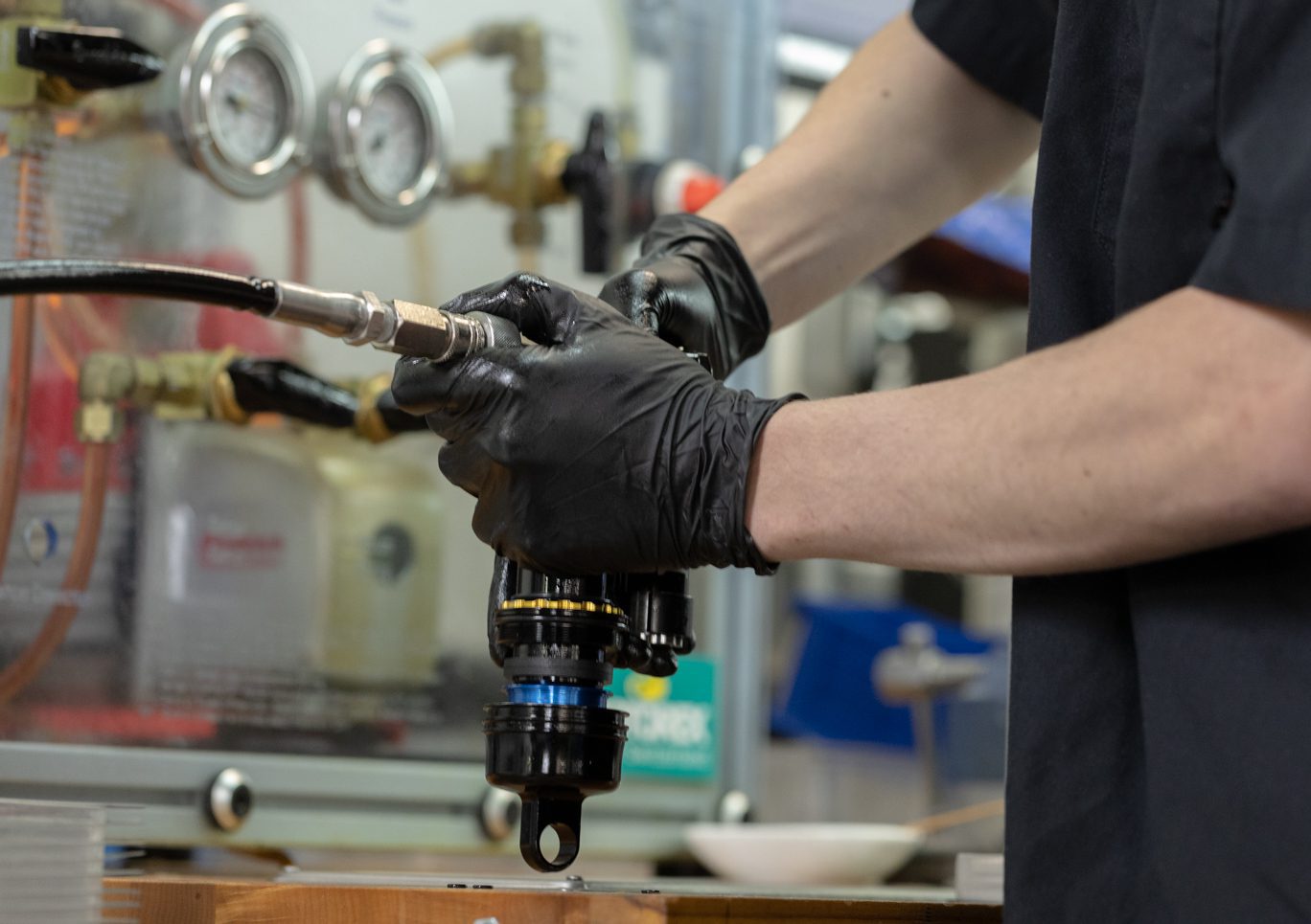
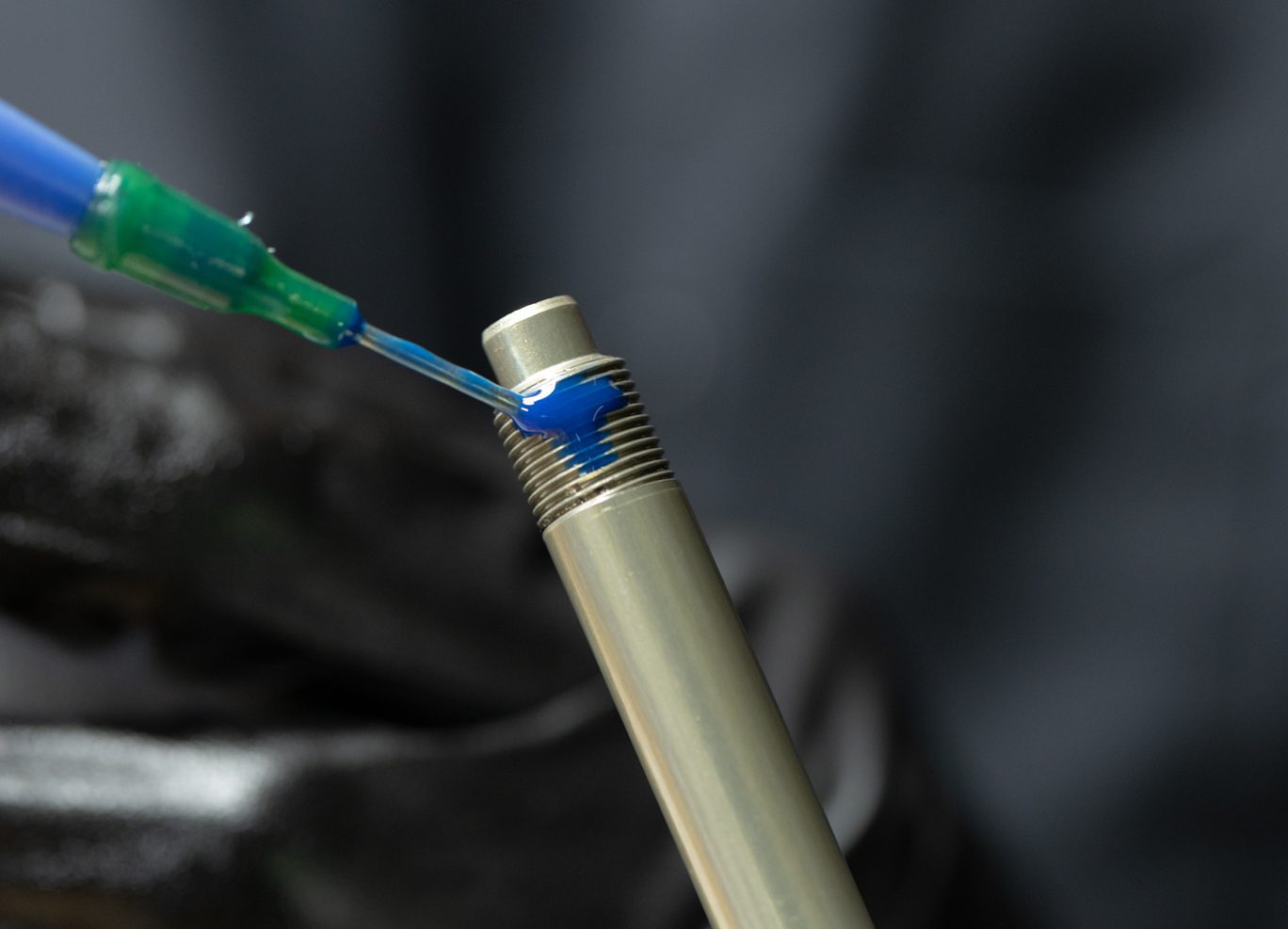
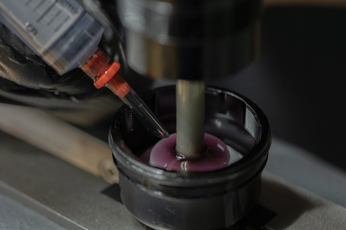
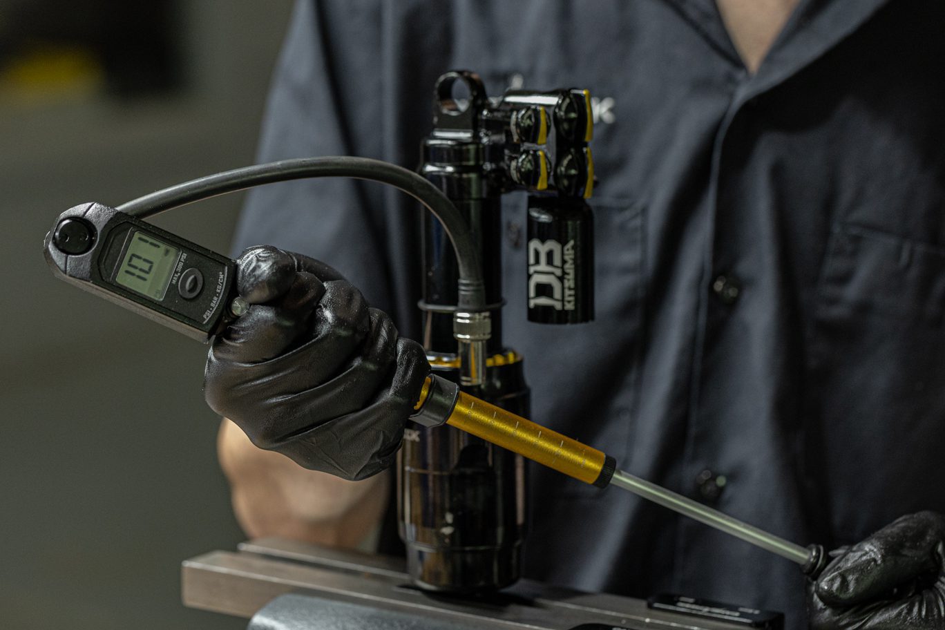
Lightly grease and install new fill port o-ring (AAD0012). Temporarily reinstall end eye. Thread fill nozzle onto valve body. Back all adjusters to fully open and open Climb Switch. Fully compress damper. Attach bladder fill tool with spacer. Attach oil fill machine to fill port per your manufacturer’s instructions.
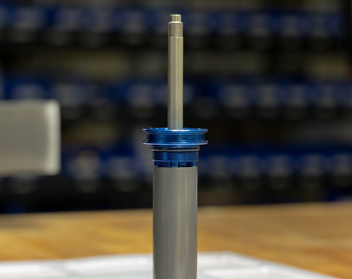
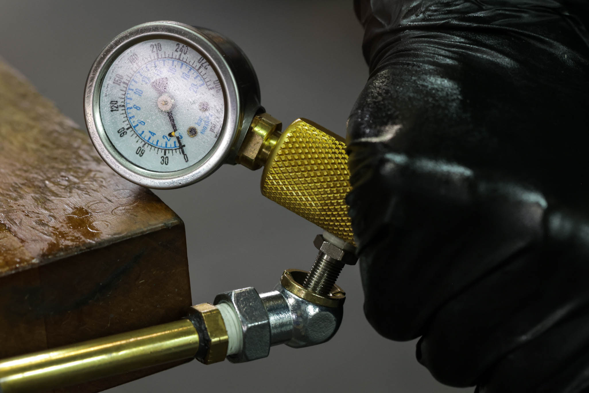
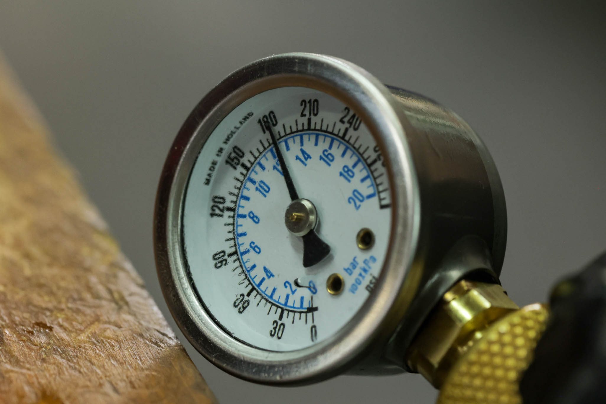
Vacuum system to (4) mbar. Pressure with Oil to (3) bar. Slowly cycle shaft finishing with shaft fully out. Cut fill and equalize pressure. Vacuum system to (4) mbar, leaving shaft out. Pressure again with Oil to (3) bar. Slowly cycle shaft finishing with shaft fully out. Cut fill.
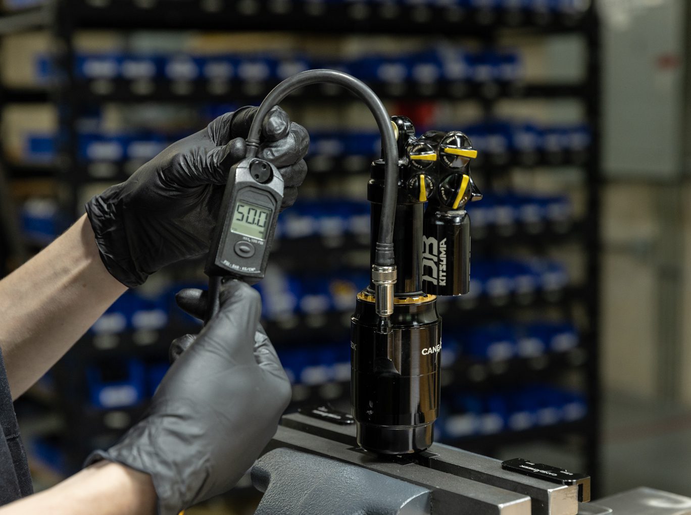
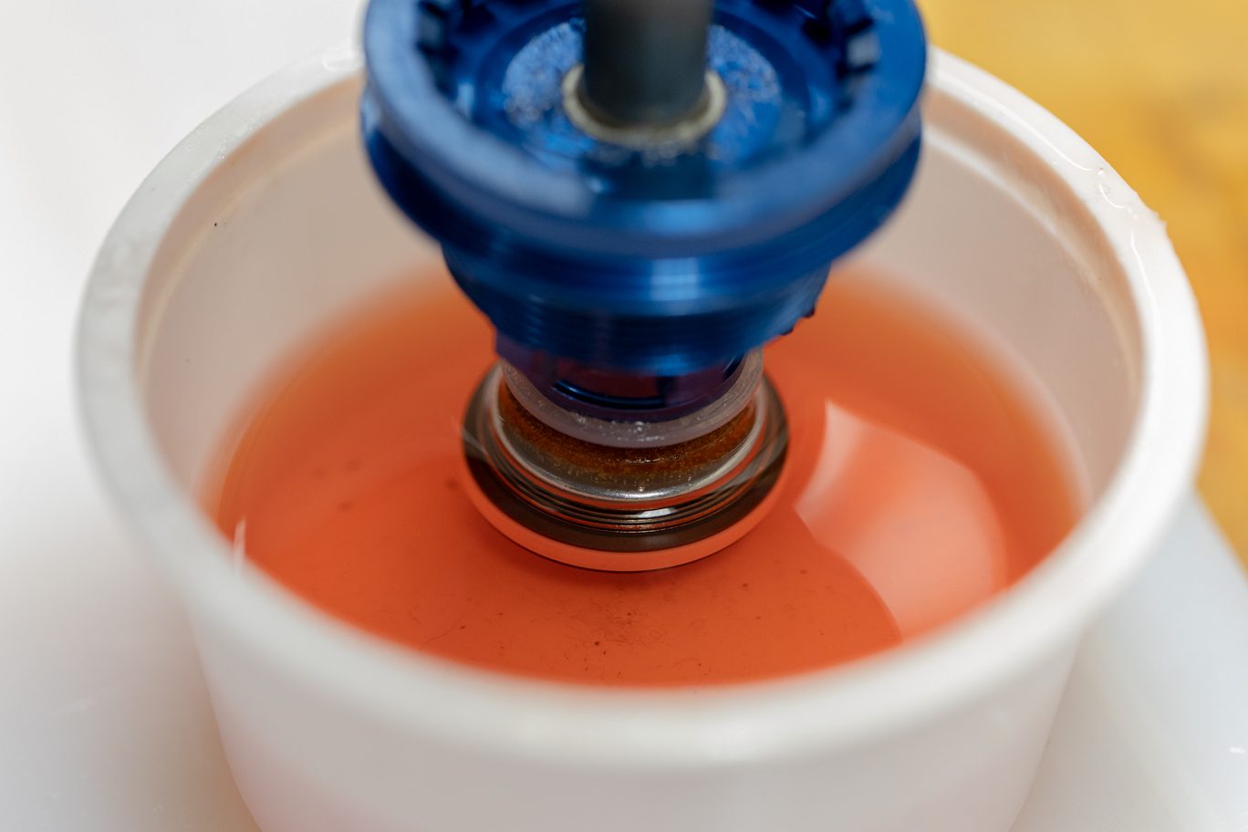
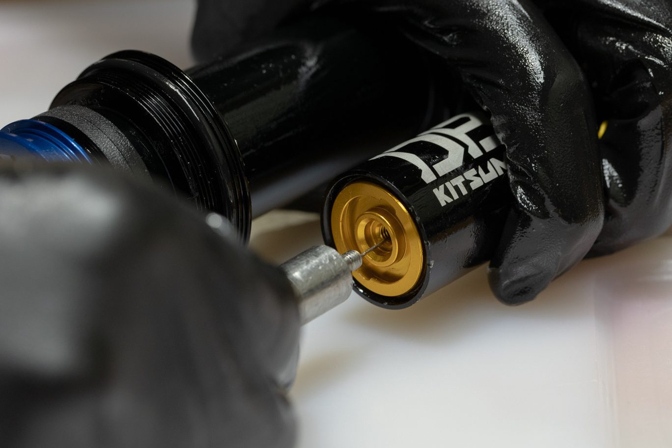
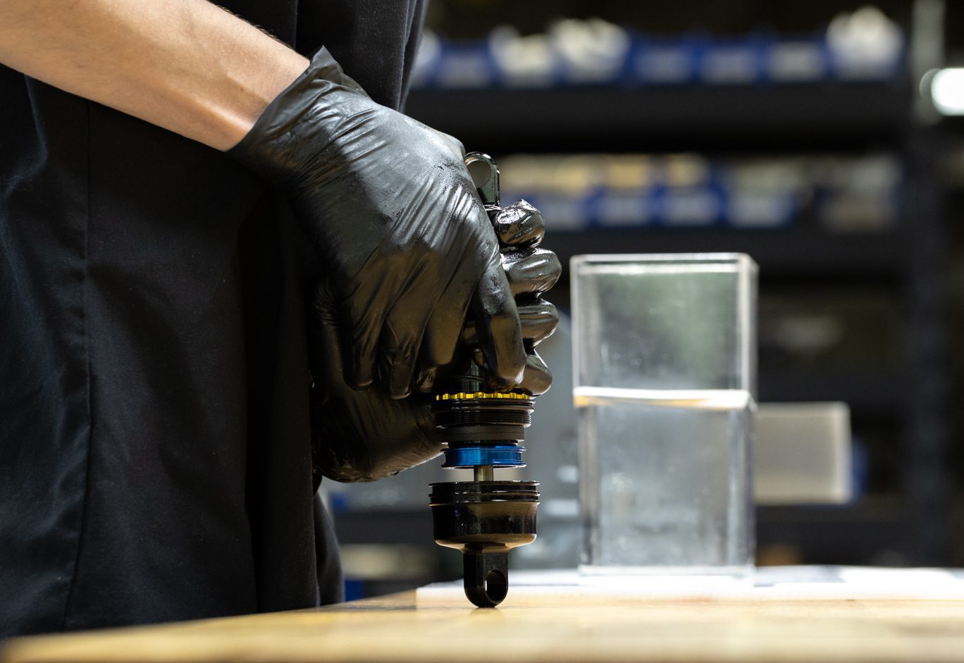
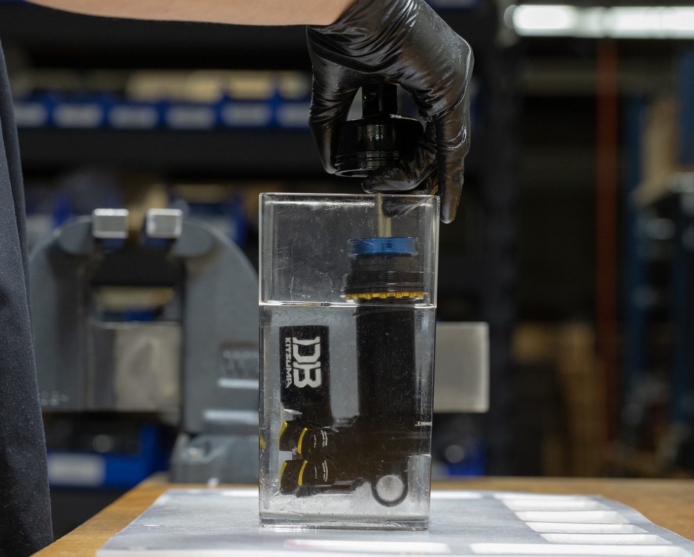
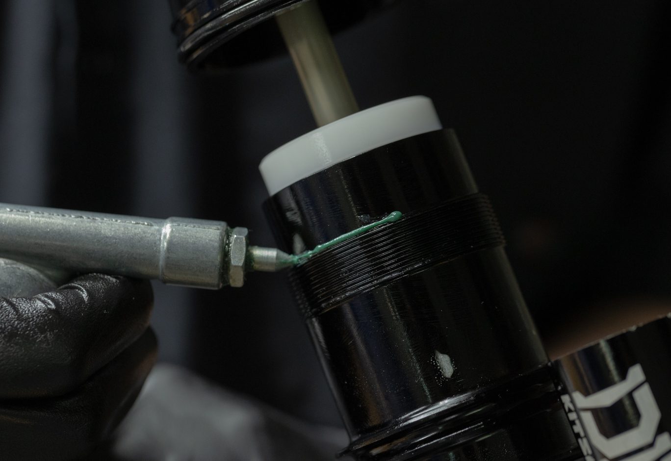
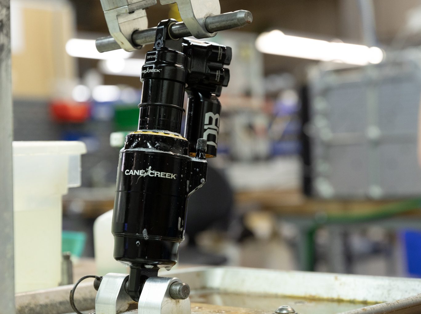
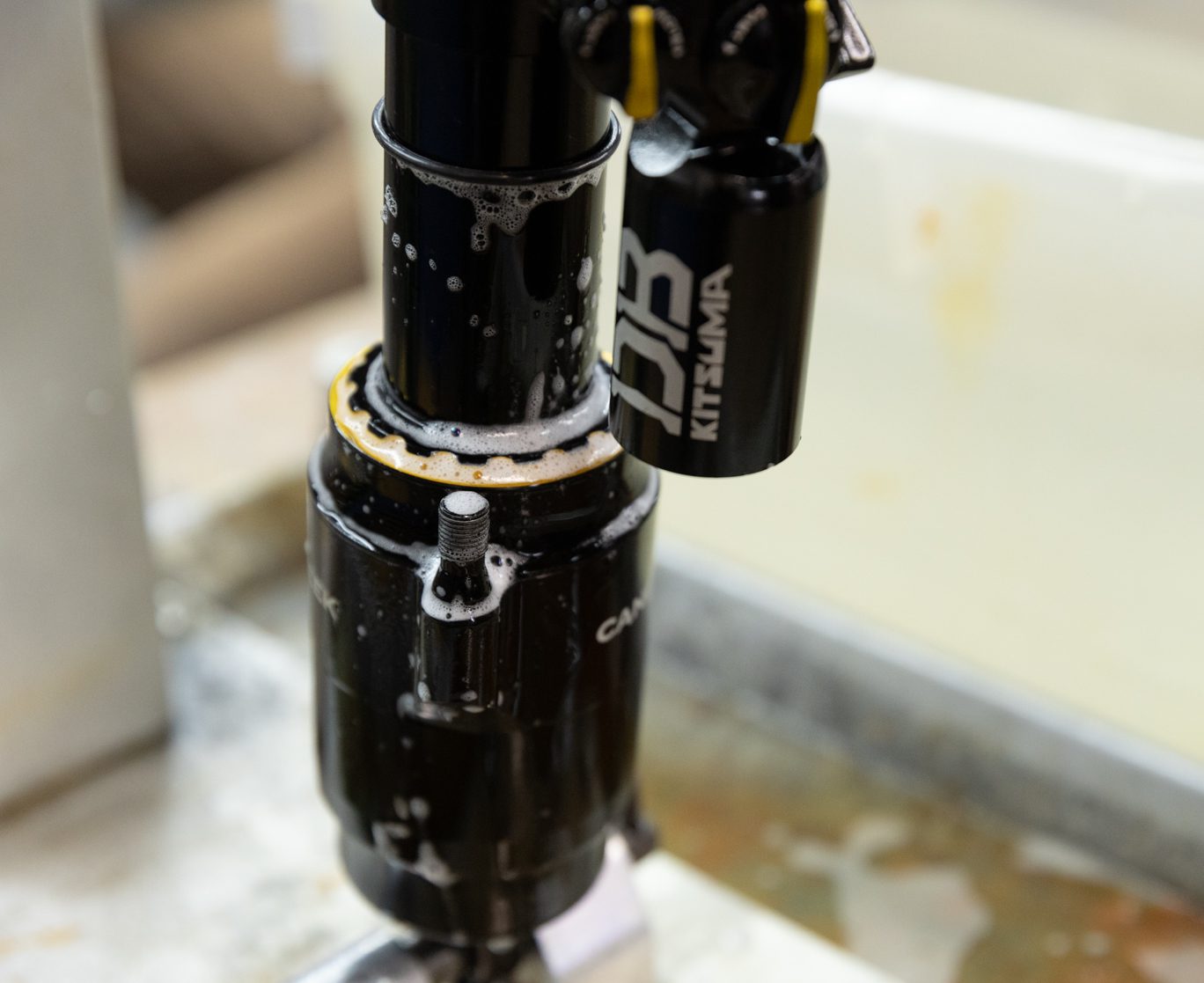
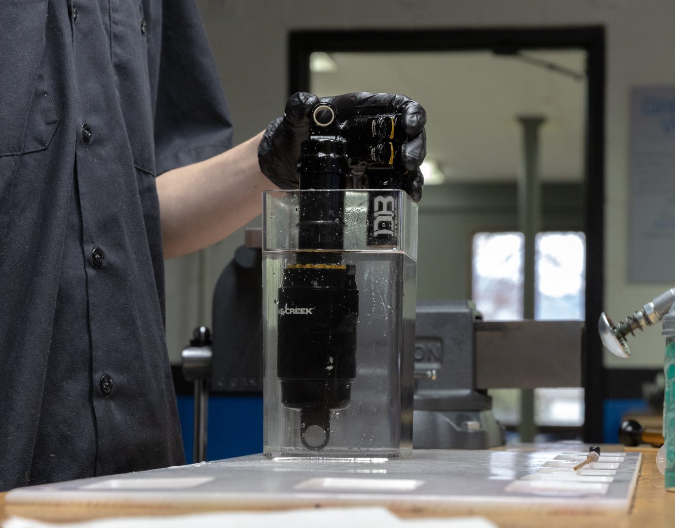
Insert gas fill needle in gas fill port on reservoir end cap. Pressurize to 11-12 bars of nitrogen. Compress shaft and ensure proper gas by observing shaft return to full extension. Submerge valve body in water to check for gas leaks. Install new res end cap o-ring (.DB11102) and fill screw.
If mechanical dyno equipment is available, run shock on dyno at this point.
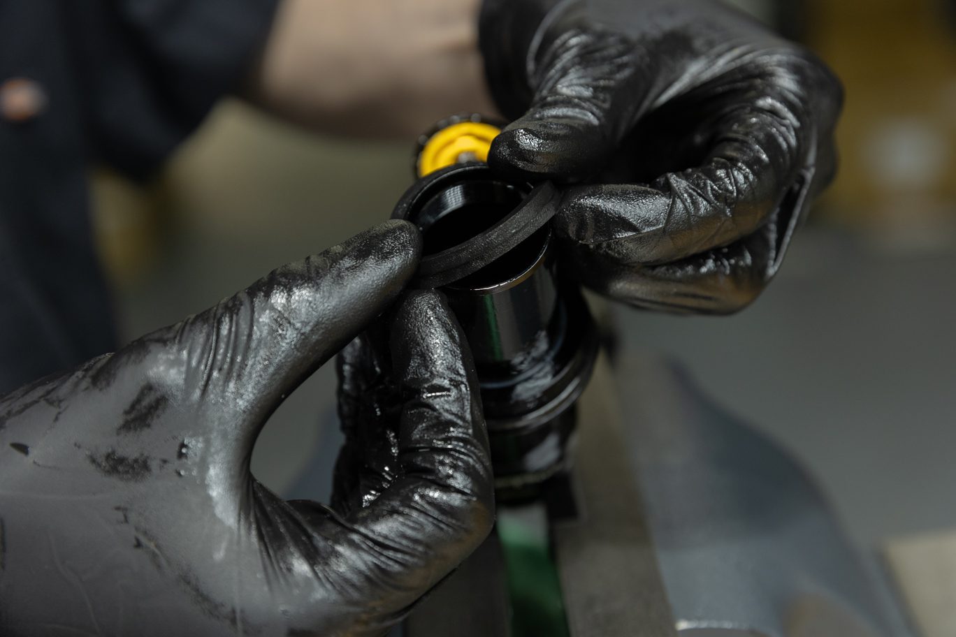
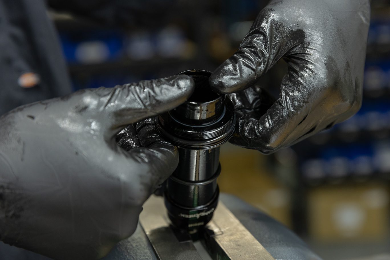
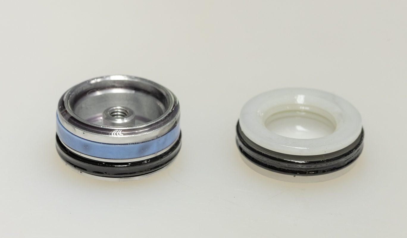
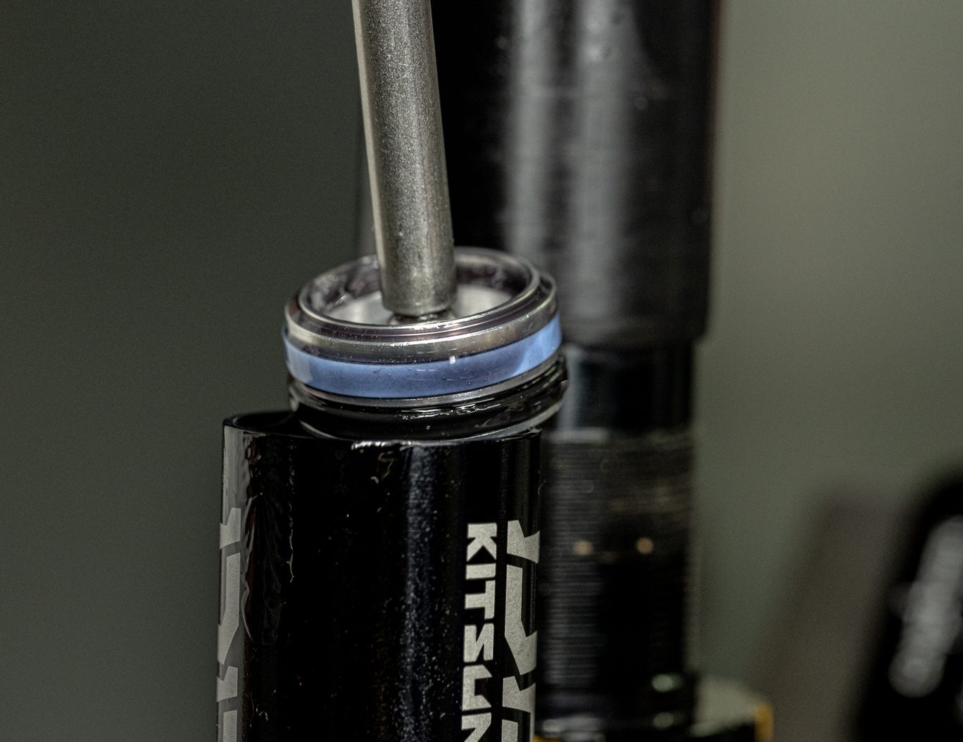
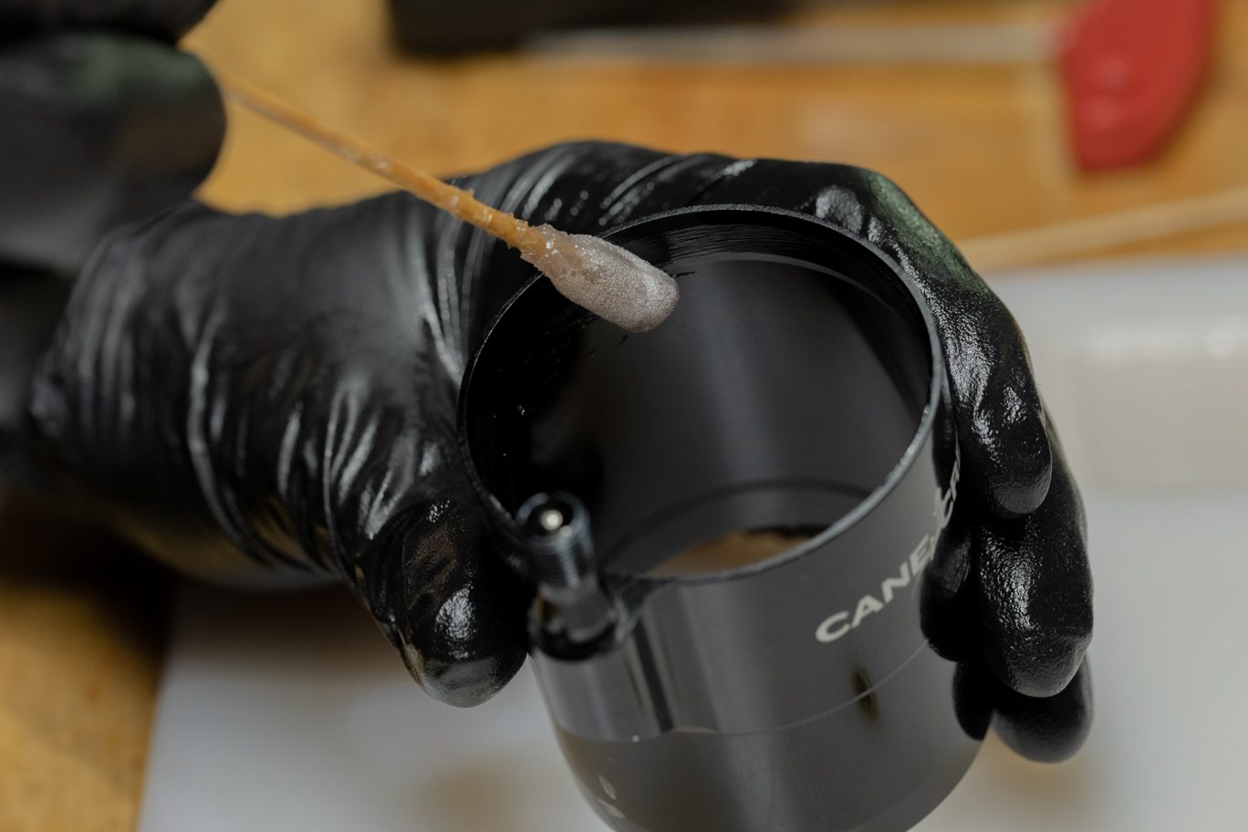
Remove end eye from shaft. Clamp shock in vise. Thoroughly grease all four sides of air piston quad ring (AAD2184). Grease the quad ring channel on the air piston. Install first air piston L-ring (ACD0132), quad ring and second L-ring with flat side of L-rings towards quad ring.
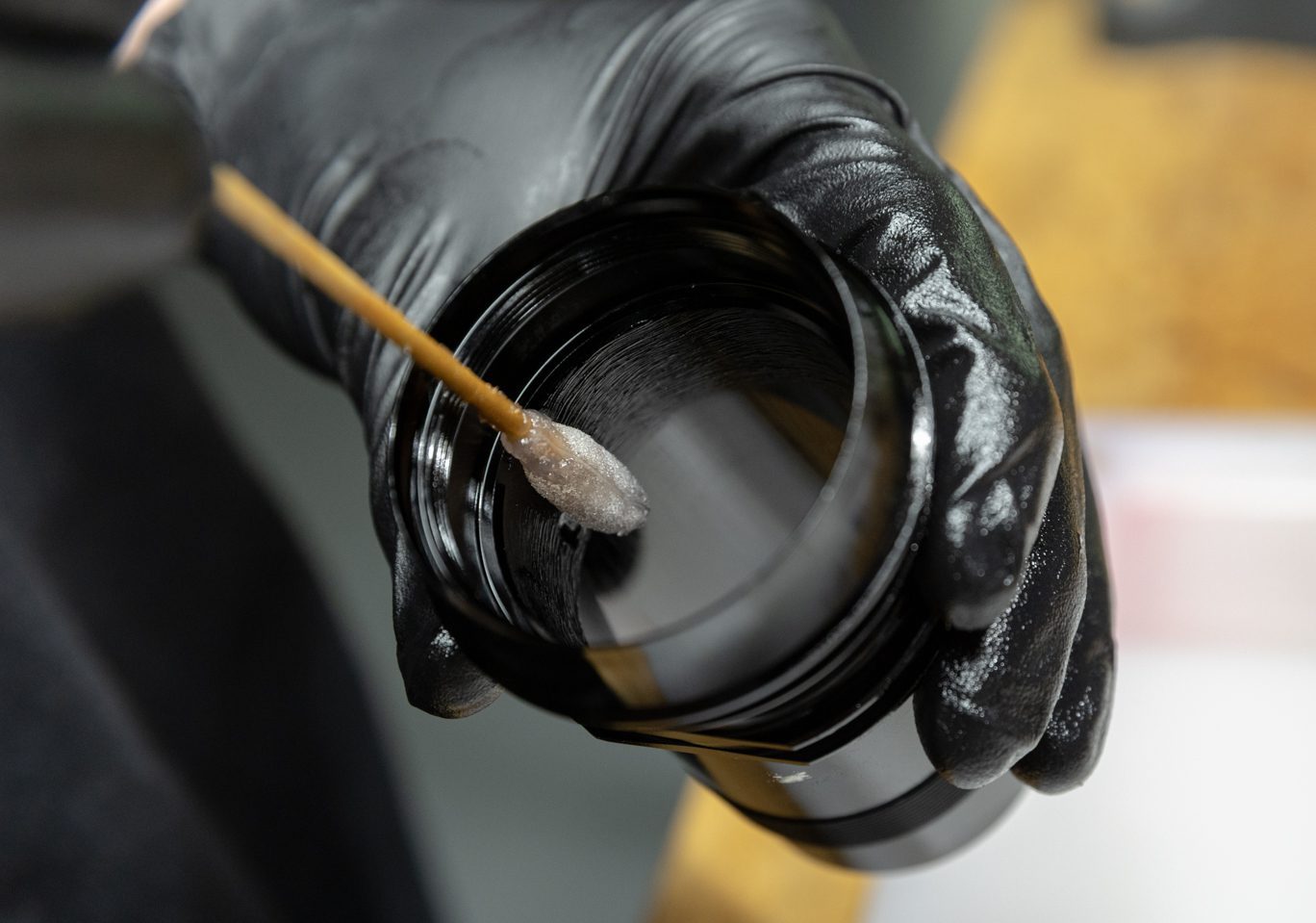
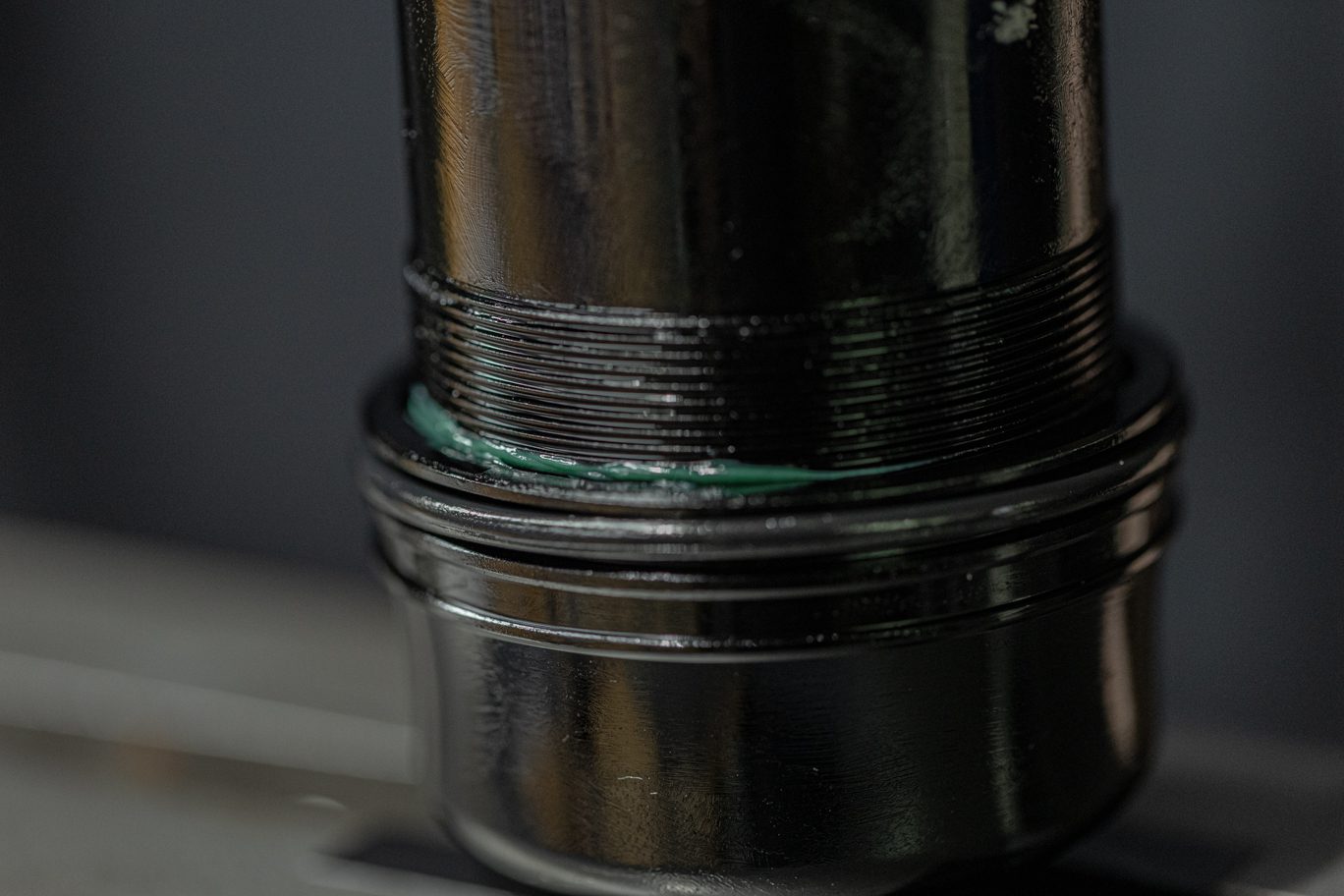
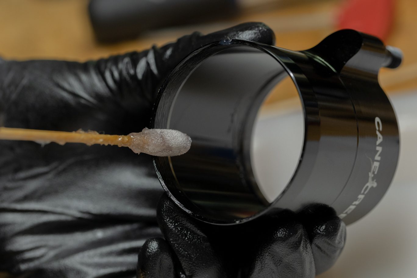
Lightly grease interior of inner air can between shelf and port hole. Lightly grease and install can retainer o-ring (AAD1102) on the topmost o-ring channel. Apply 2-4 cms of bicycle grease to the inner threads on the inner air can. Install inner air can past the air piston until it contacts air seal head.
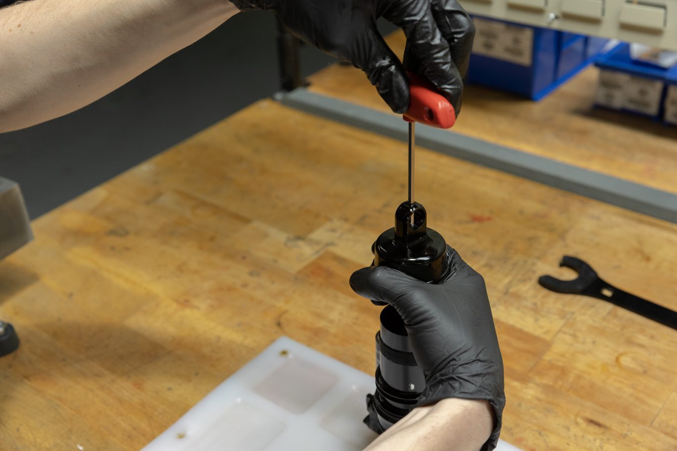
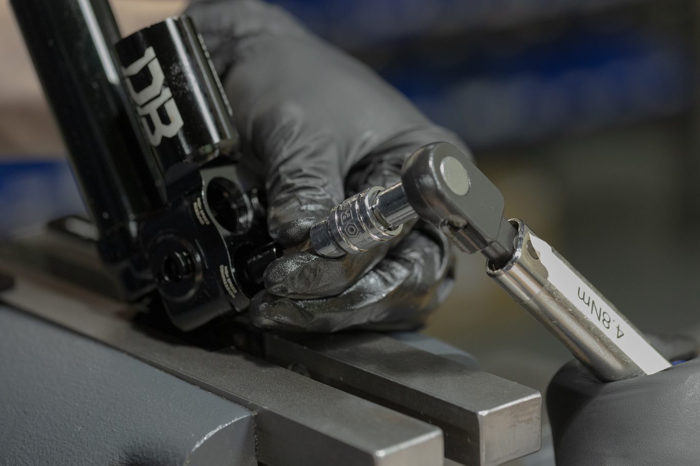
Lightly grease and install end eye can retaining o-ring (AAD1102) in topmost outer groove on end eye. Lightly grease and install shaft sealing o-ring (ACD0302) by gently working pass shaft threads until flush. Reinstall bottom out bumper and any stroke reduction needed. Apply blue Loctite (243) to threads on end eye and shaft. Thread end eye onto shaft. Insert 4mm Allen through end eye and torque end eye to 4.8 Nm using 1/2″ crowsfoot.
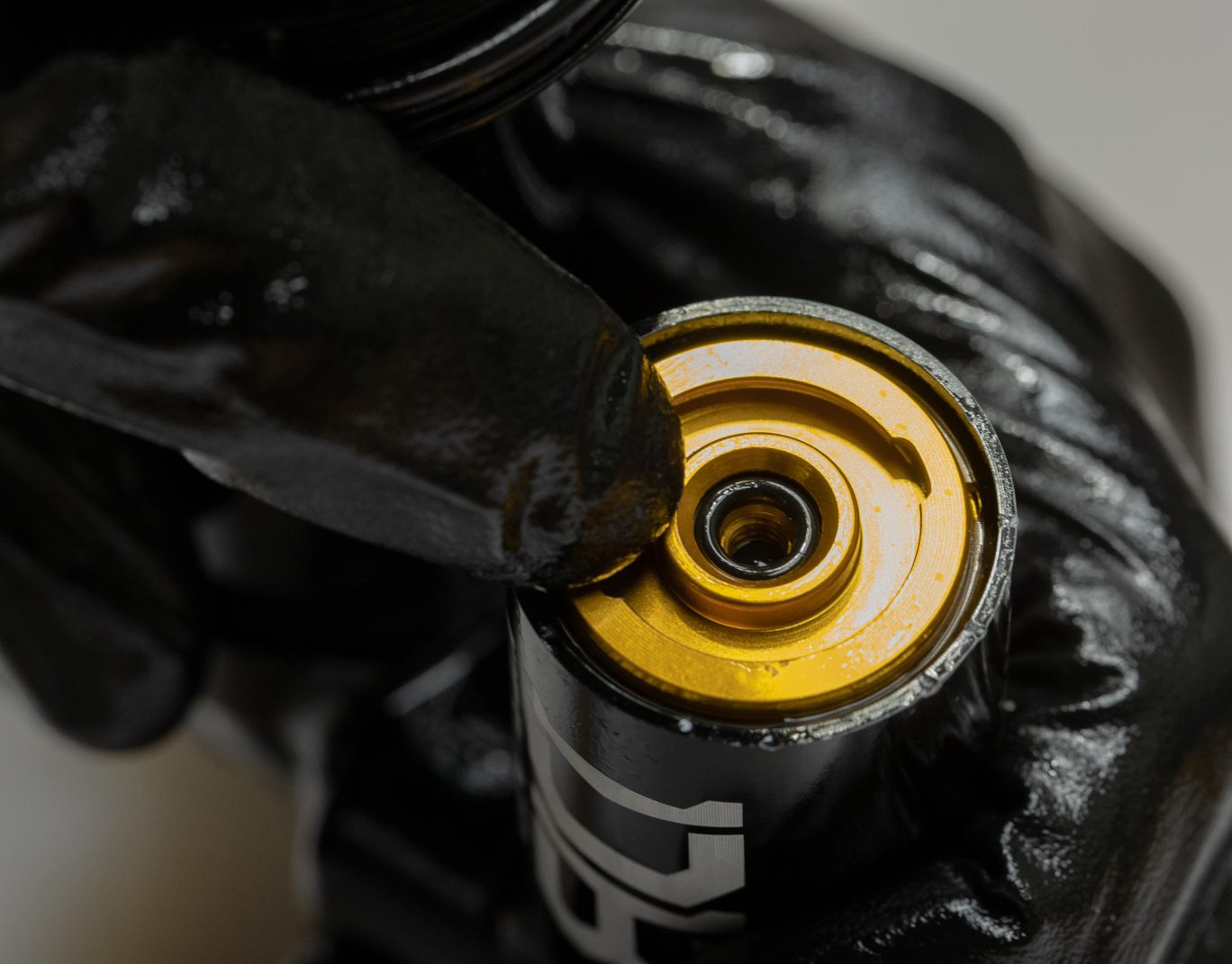
Apply 2-4 cms of bicycle grease to the outer threads on the inner air can. Flip shock in vise. Add 5 ml of Royal Purple to end eye. Hand thread inner air can onto end eye. Hand thread air seal head onto inner air can. Once both are hand tight, use Air Seal Head tool to tighten. Torque to 22.6 Nm.
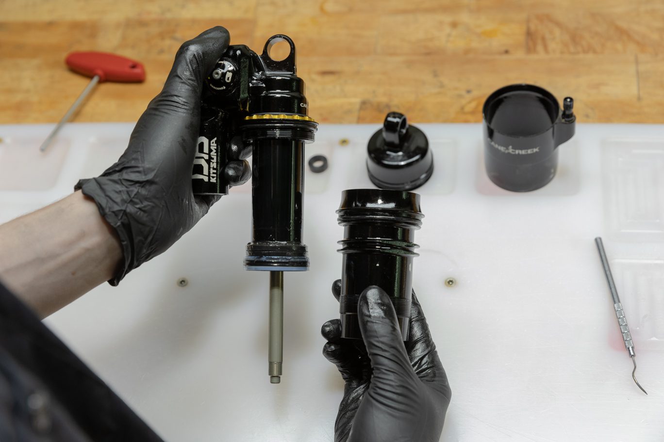
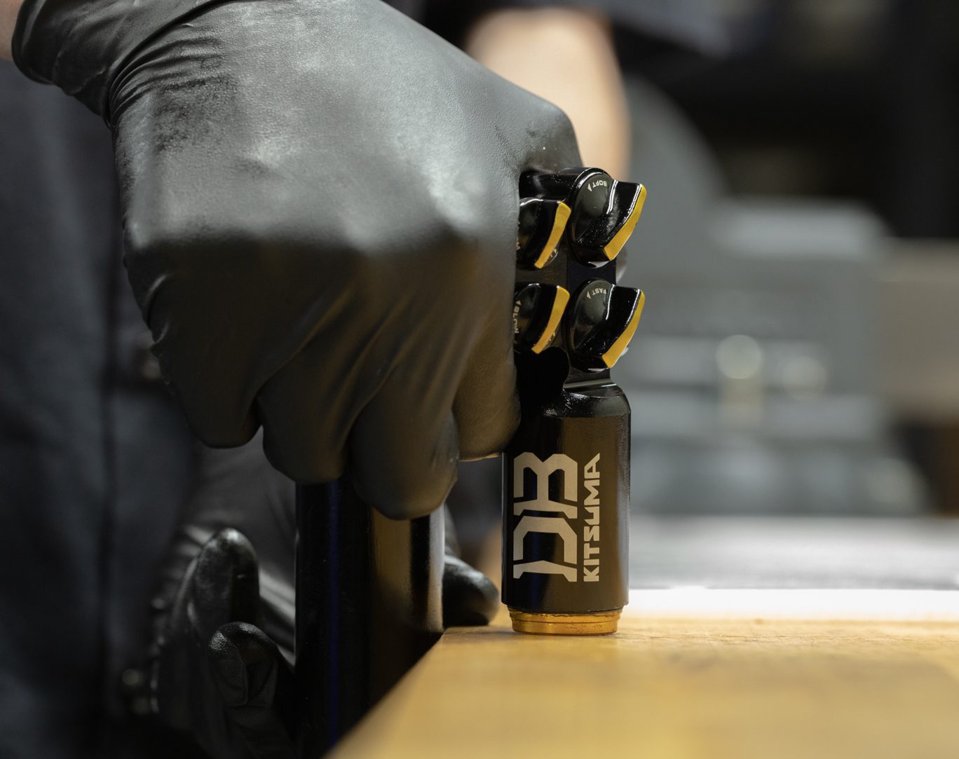
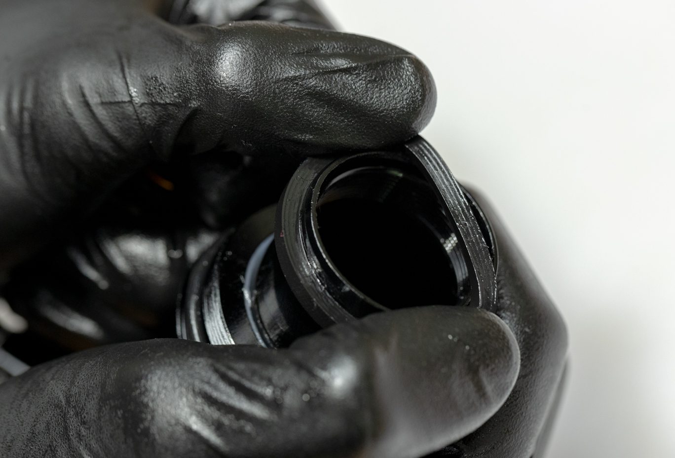
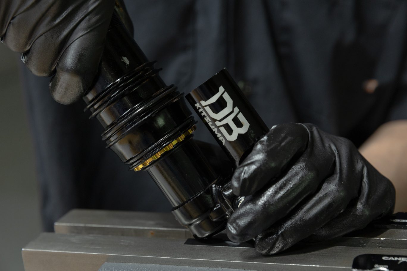
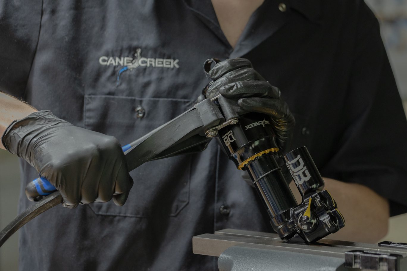
Lightly grease the interior ridges on the outer air can. Flip shock in vise. Install any volume reduction bands. Install air can with air valve towards cylinder head. Seating air can may require a strap wrench. Set desired air valve placement. Ensure air valve will not contact the reservoir tube at compression. Install dry air can retaining o-ring (AAD0012)

Monday: 10:00 am – 5:00 pm
Tuesday – Thursday: 10:00 am – 7:00 pm
Friday: 10:00 am – 5:00 pm
Saturday – Sunday: Closed