We Are Open and Have Returned to Normal Operations
Previous slide
Next slide
June 2022 orig.
Any damage or issues resulting from improper service will not be covered by warranty. If you have a fork still in its original warranty period and do not wish to void your warranty, please contact an authorized Cane Creek service center.
These service instructions cover the basic service procedures using standard service kits. If your suspension requires parts beyond standard replacement parts – CSU, compression rods, etc. – please consult your authorized Cane Creek service center or contact us at our Cane Creek Support Center.
These instructions cover just the coil spring leg of a complete 100 hour service. Combine these instructions with the appropriate damper side and 50 hour lower service to get a complete 100 hour fork service.
Additionally, you can send the damper for a service with an authorized Cane Creek service center.
none
none
Torx wrenches – T10
Sockets – 15mm & chamfer-less 30mm
Crowsfoot wrenches – 22mm
Open Ended Box wrenches – 22mm
8mm shaft clamp (if needed)
Torque wrenches
Pick
Suspension Grease
PolyLube Grease
Torque & Loctite Chart
| Part | Torque Spec | Loctite Spec |
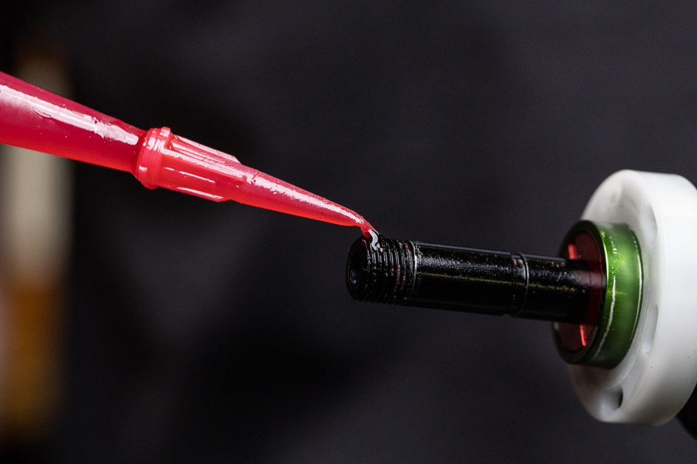
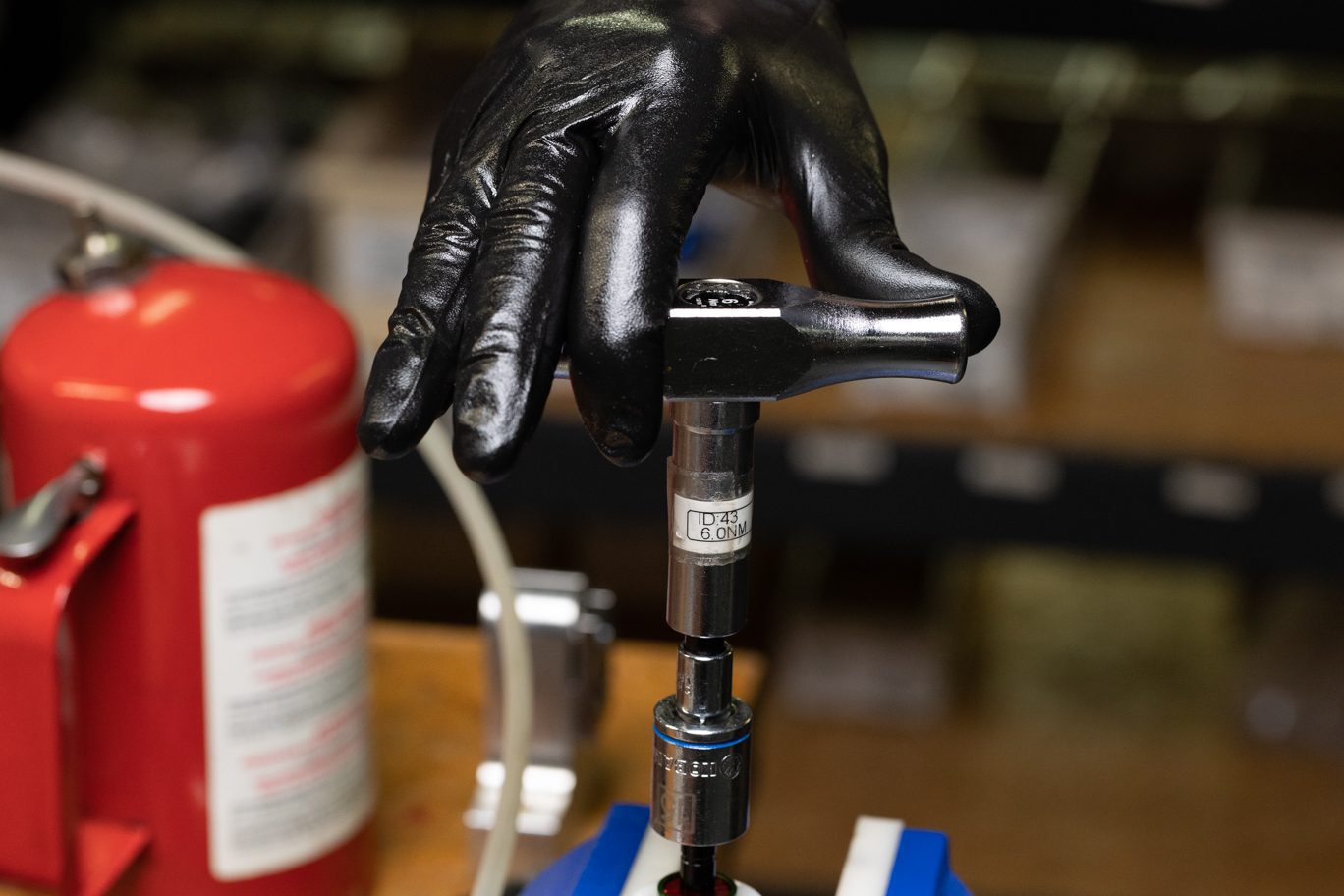
| Comp Rod Stop | 6 Nm | 263 (Red) |
| Seal Head Install | 16 Nm | None |
| Preloader | 36 Nm | 243 (Blue) |
| Preloader Cap Screw | 1.6 Nm | 243 (Blue) |
Review all related TSBs before performing any service.
Prior to beginning damper service, remove the lower assembly per the 50 hour service instructions.
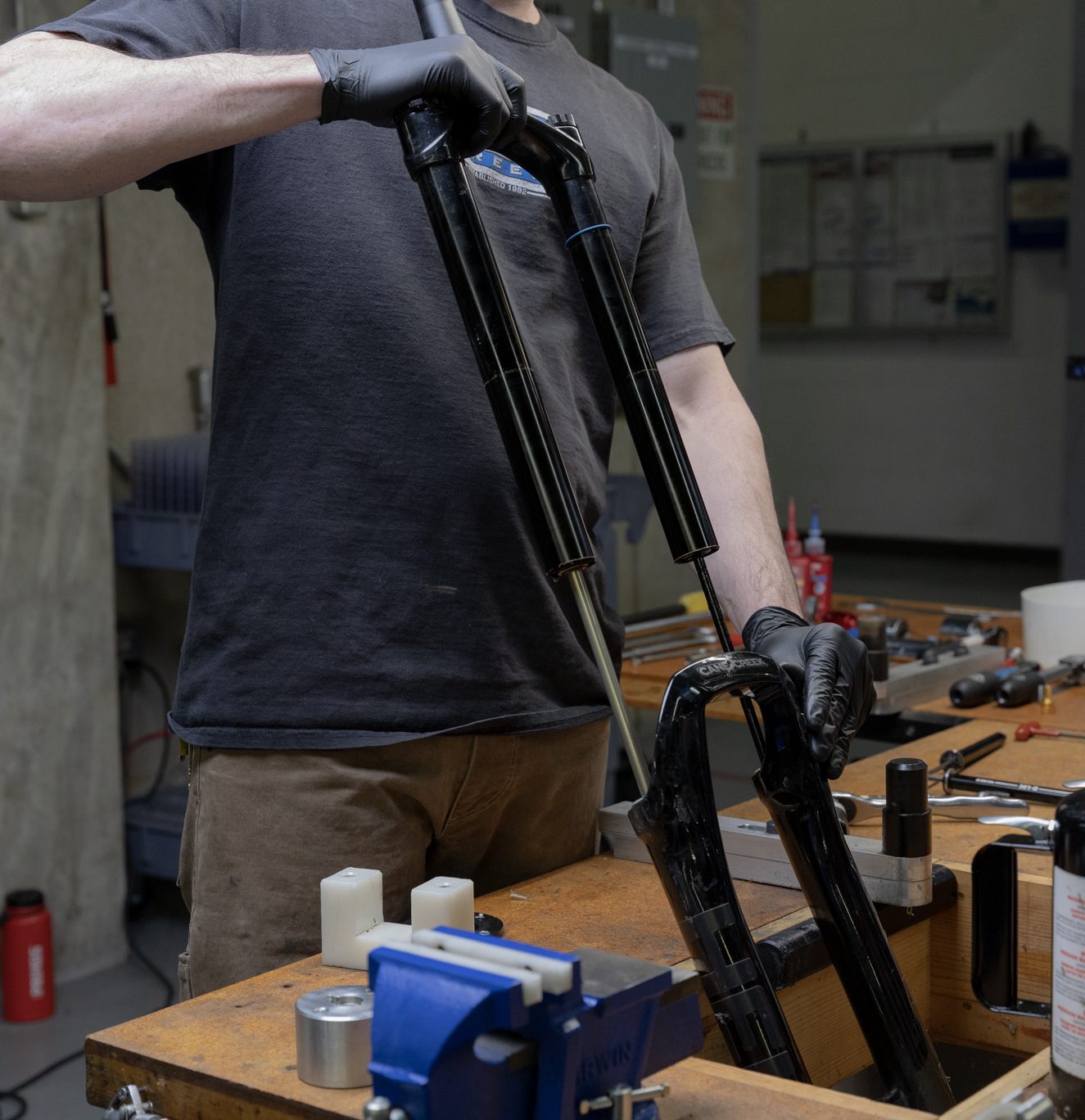
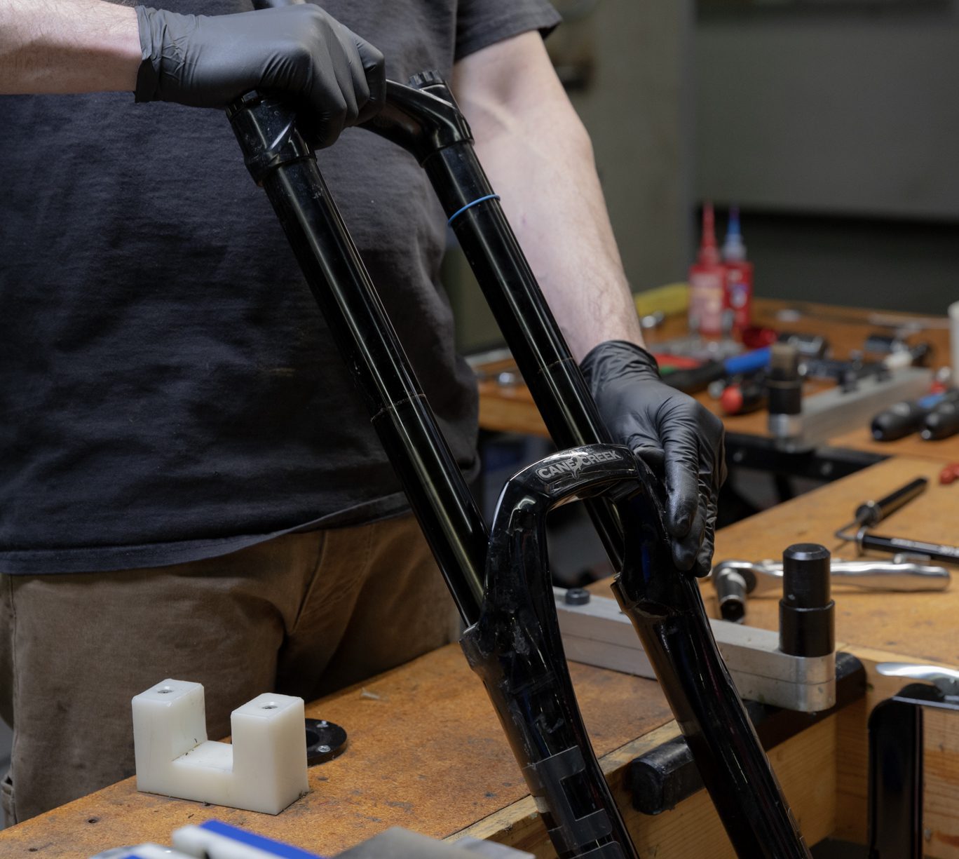
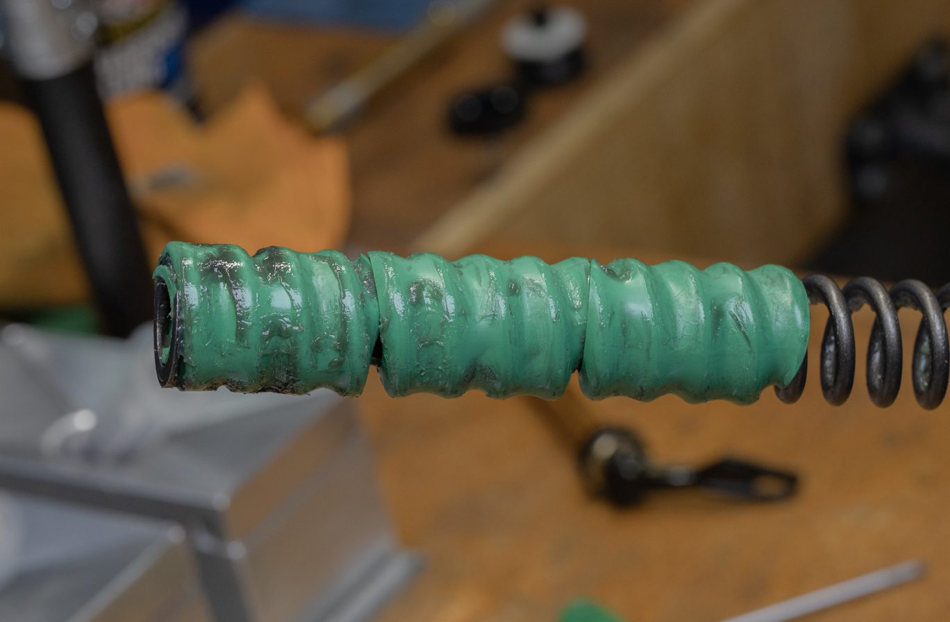
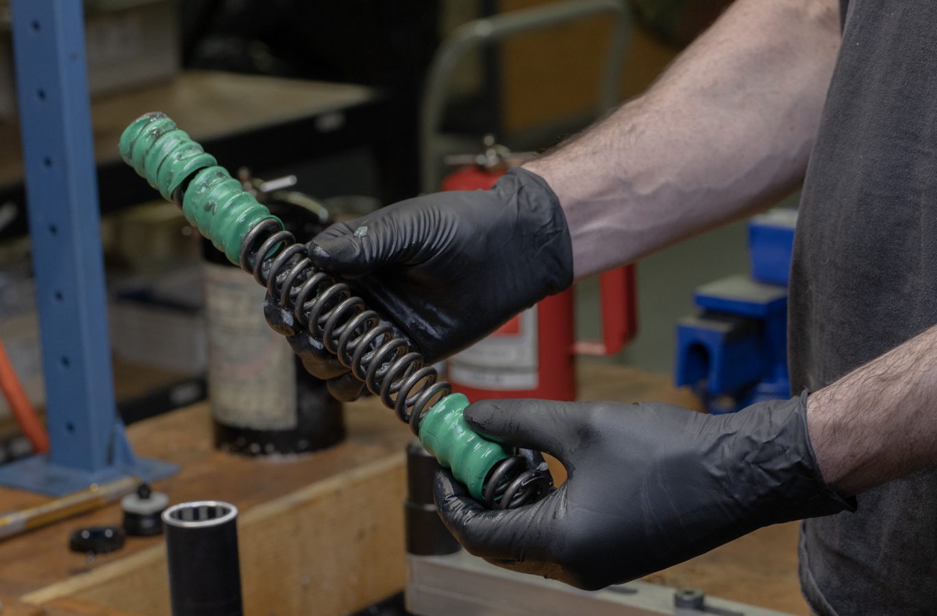
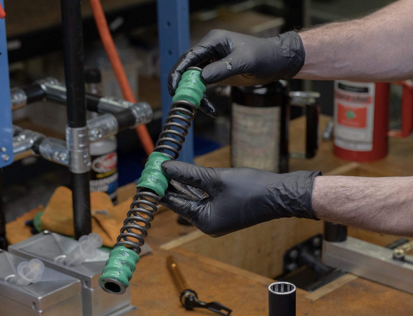
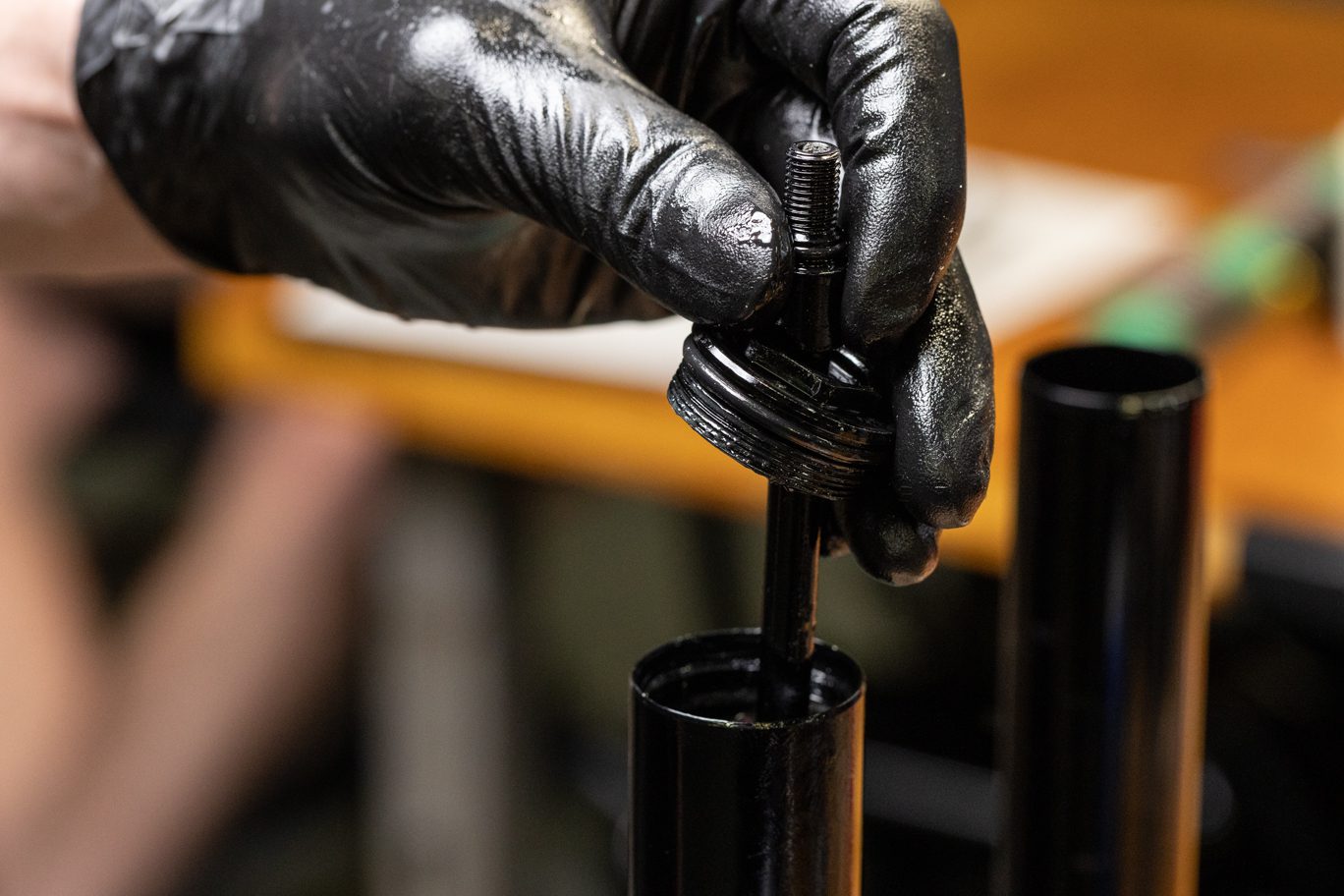
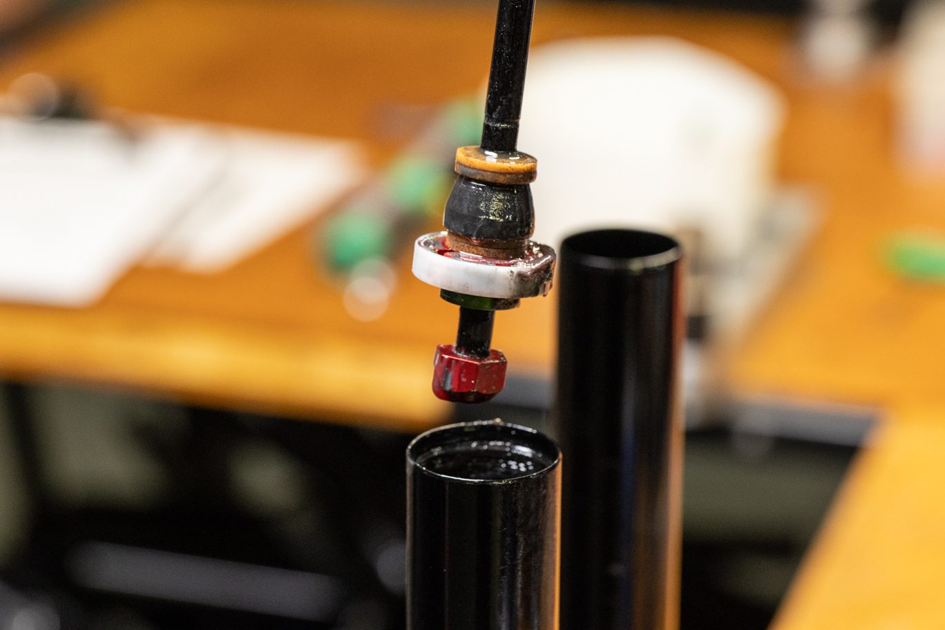
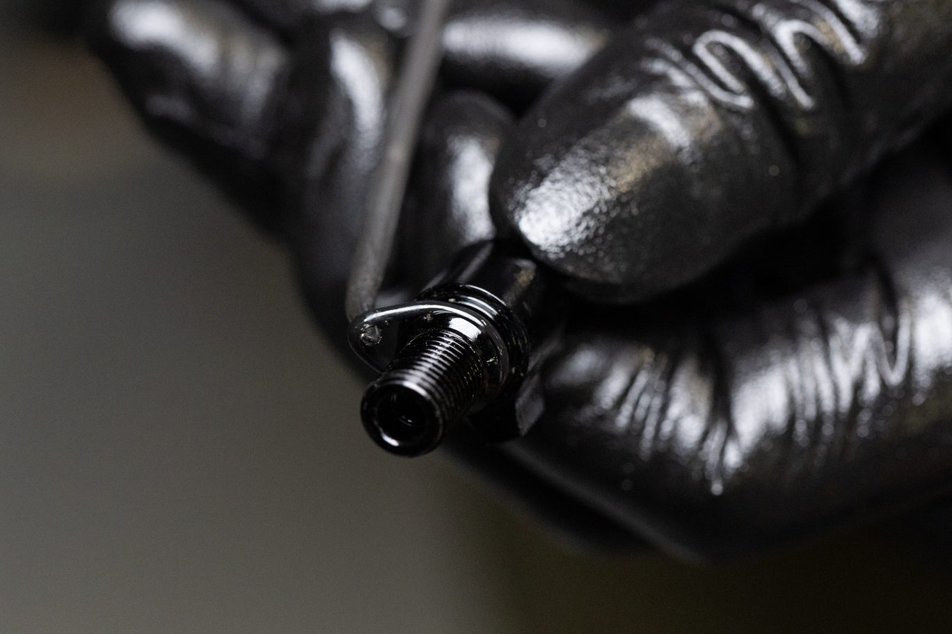
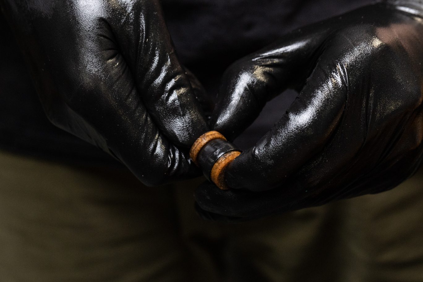
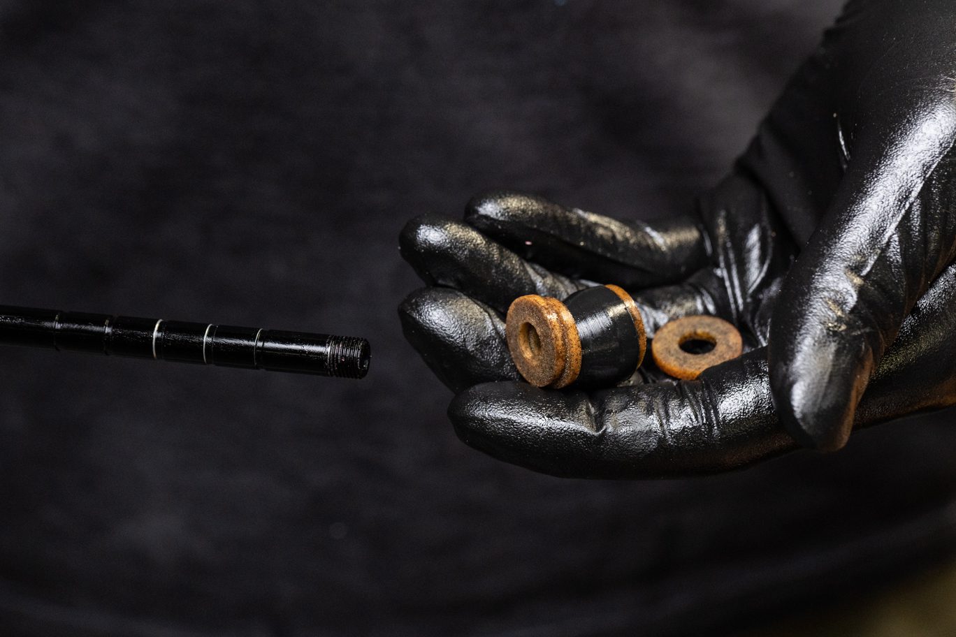
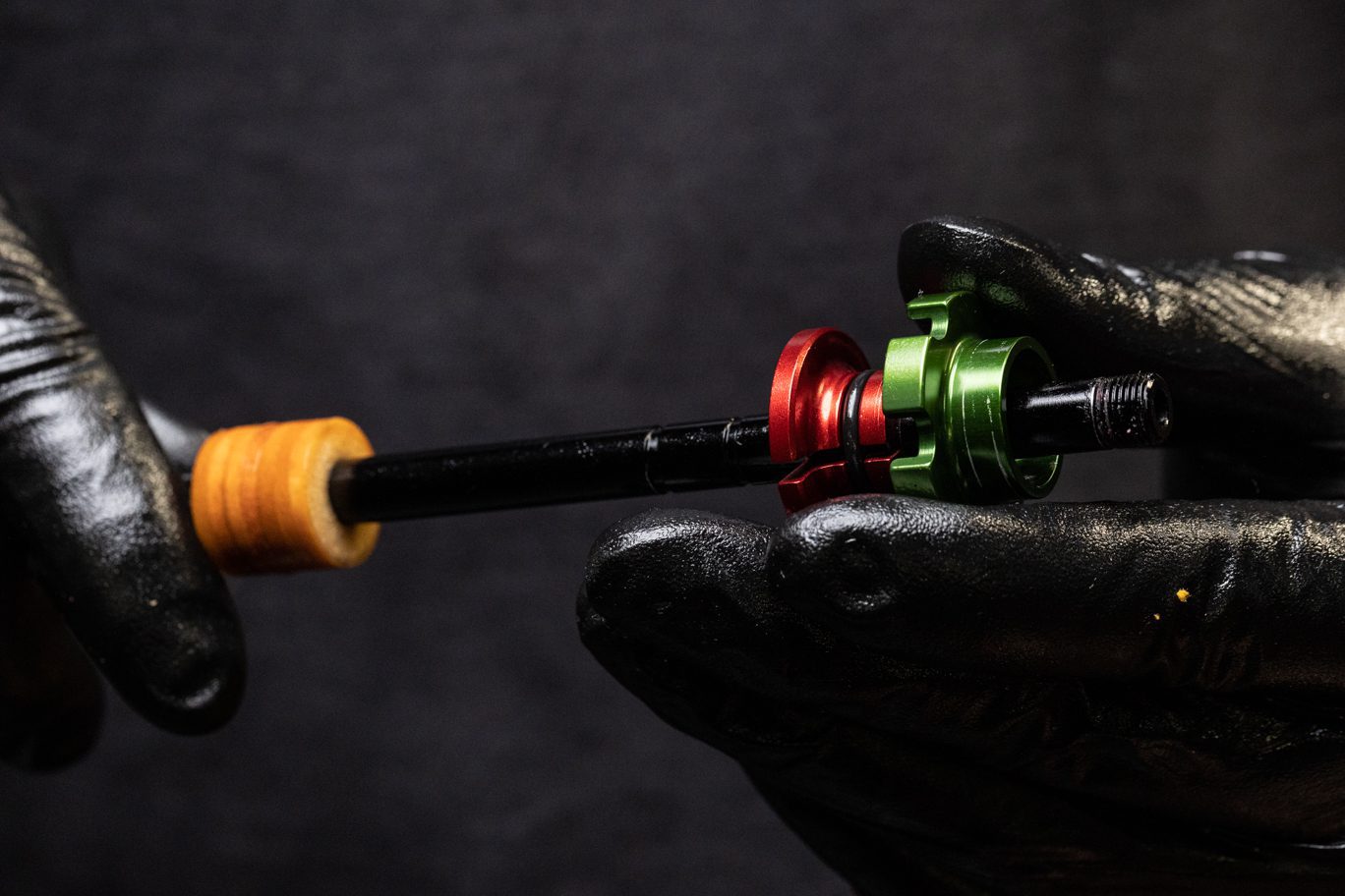
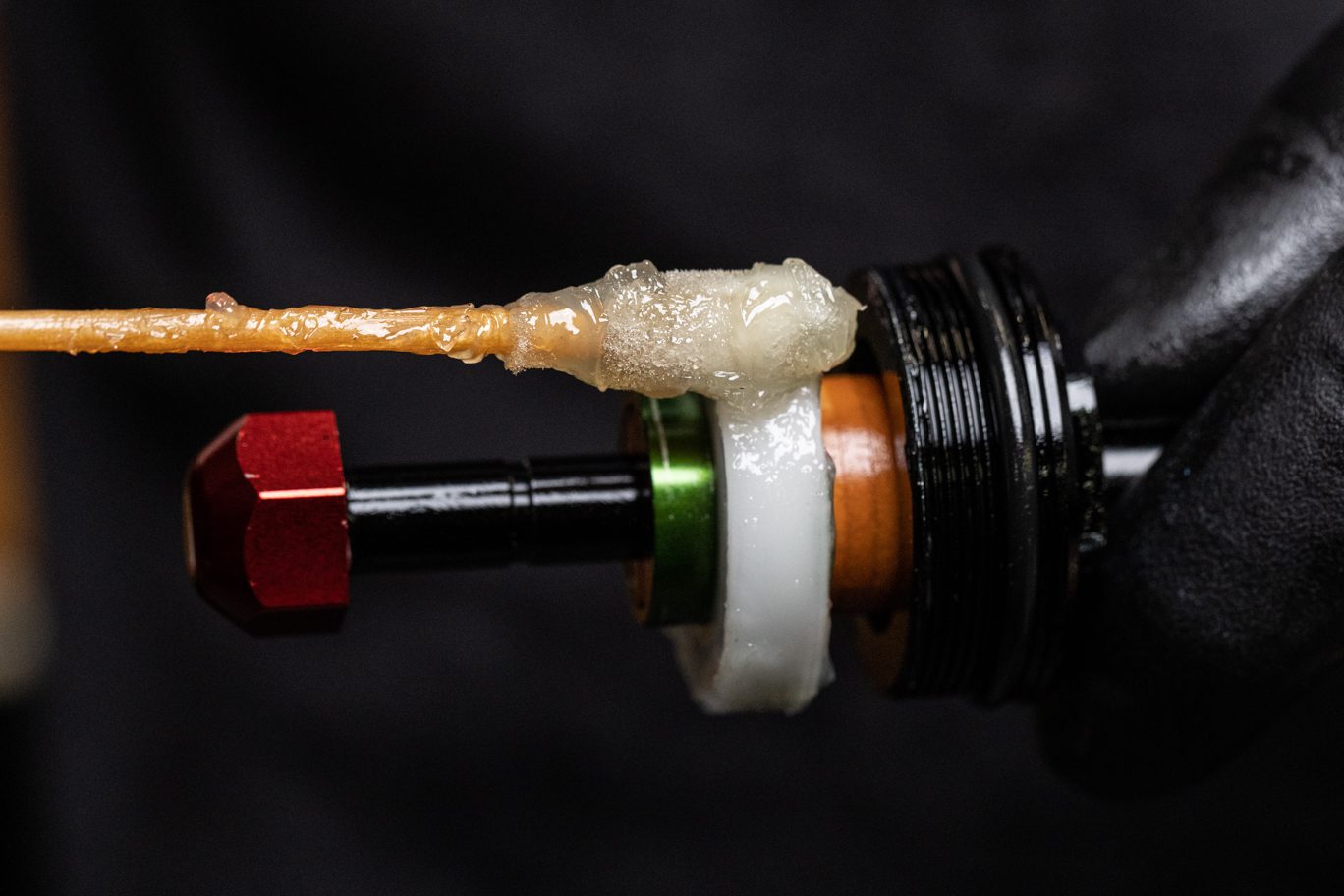
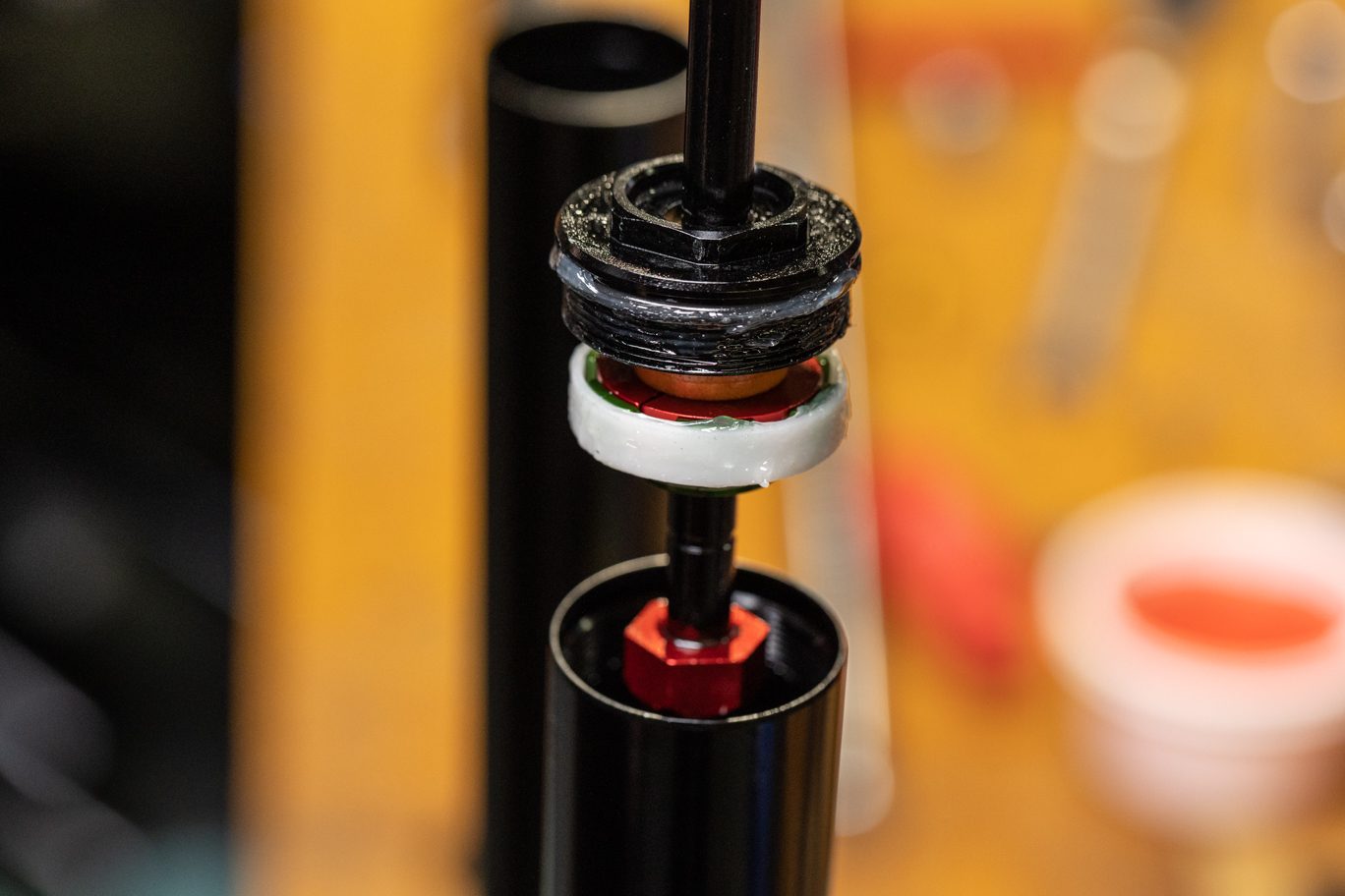
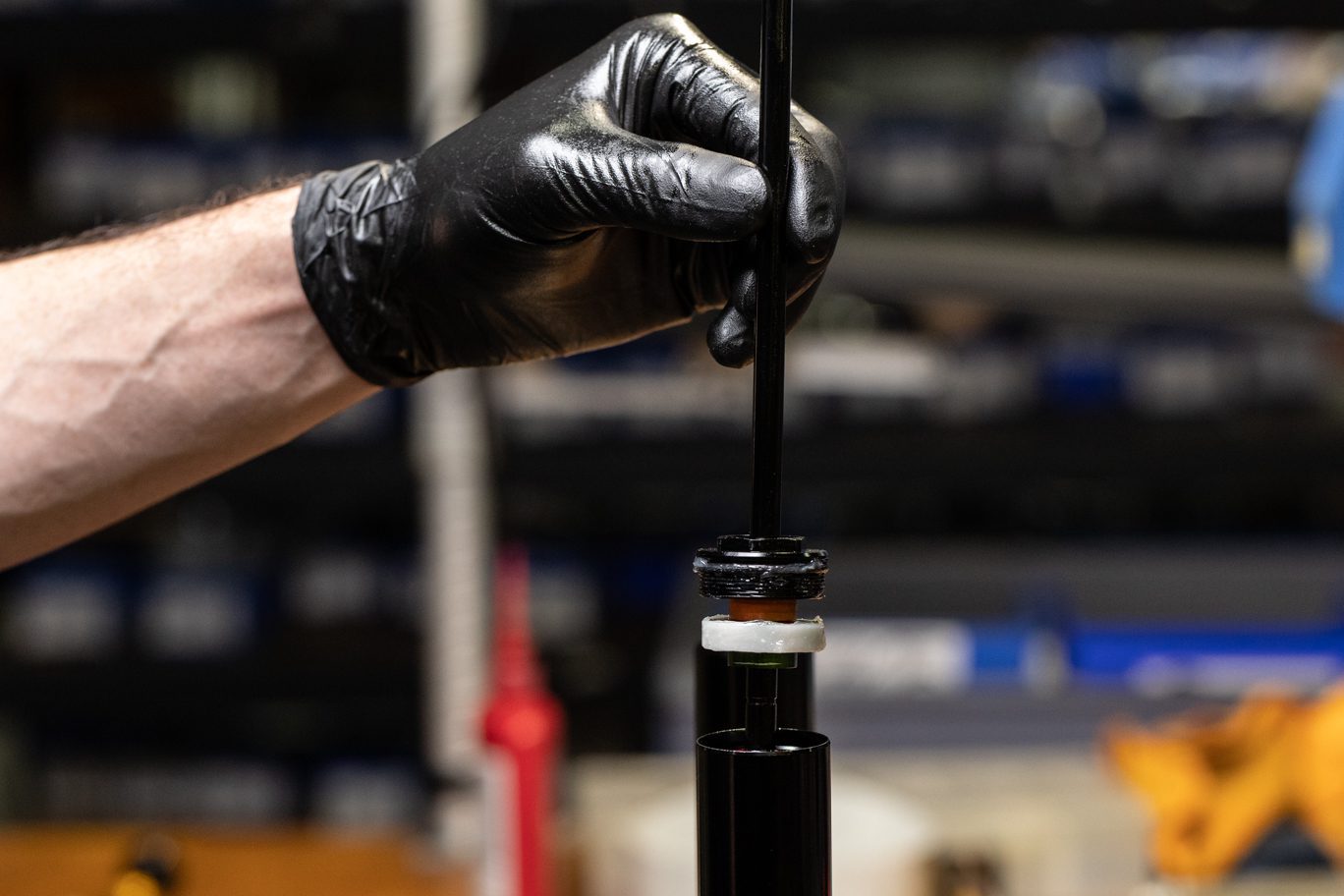
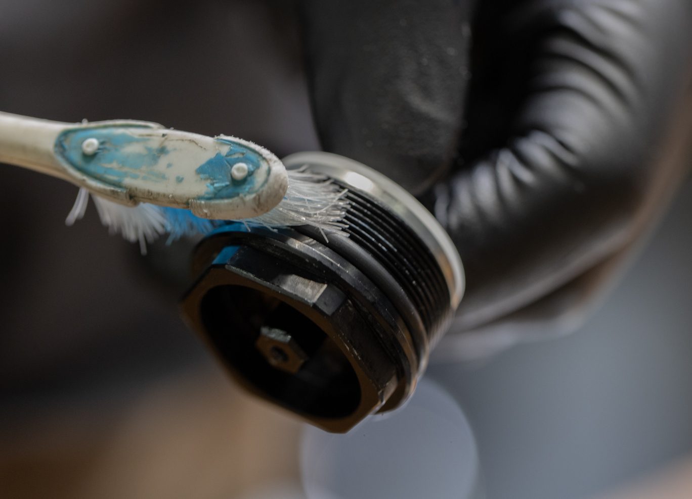
Using a 22mm open ended wrench, unthread coil seal head from stanchion. Remove coil compression rod assembly. Remove and discard footnut o-ring. Clean all oil from compression rod assembly using diluted alcohol. Inspect top out bumpers. Note that top out bumpers and configuration from factory may vary from photos here.
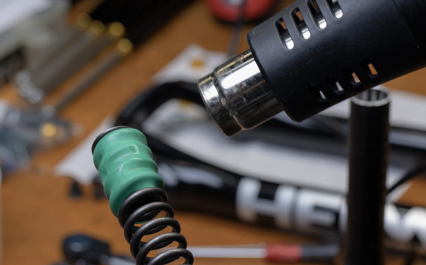
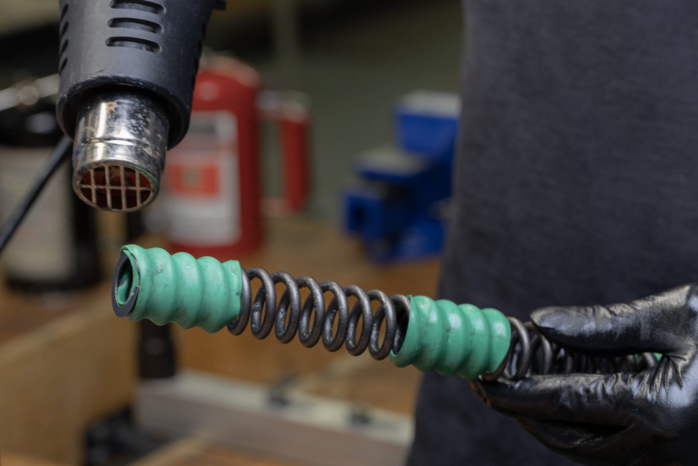
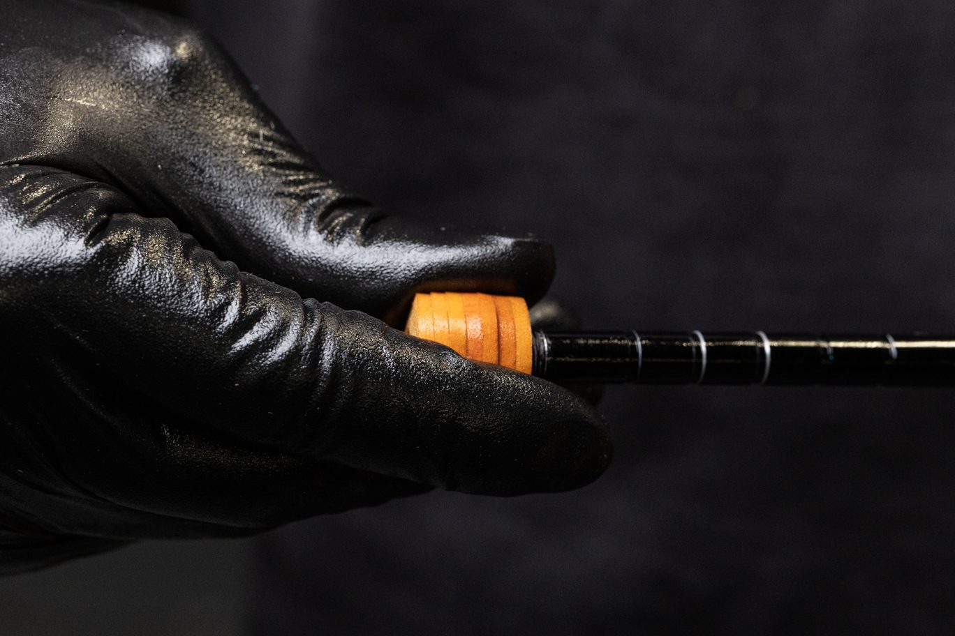
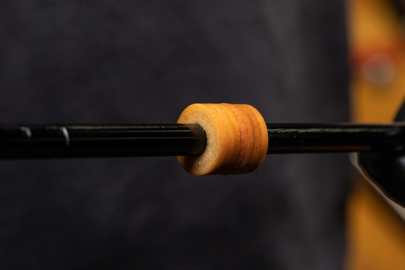
If needed to replace or add top out bumpers only.
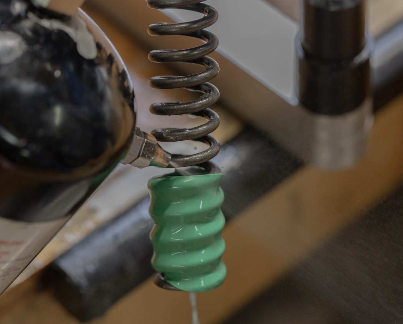
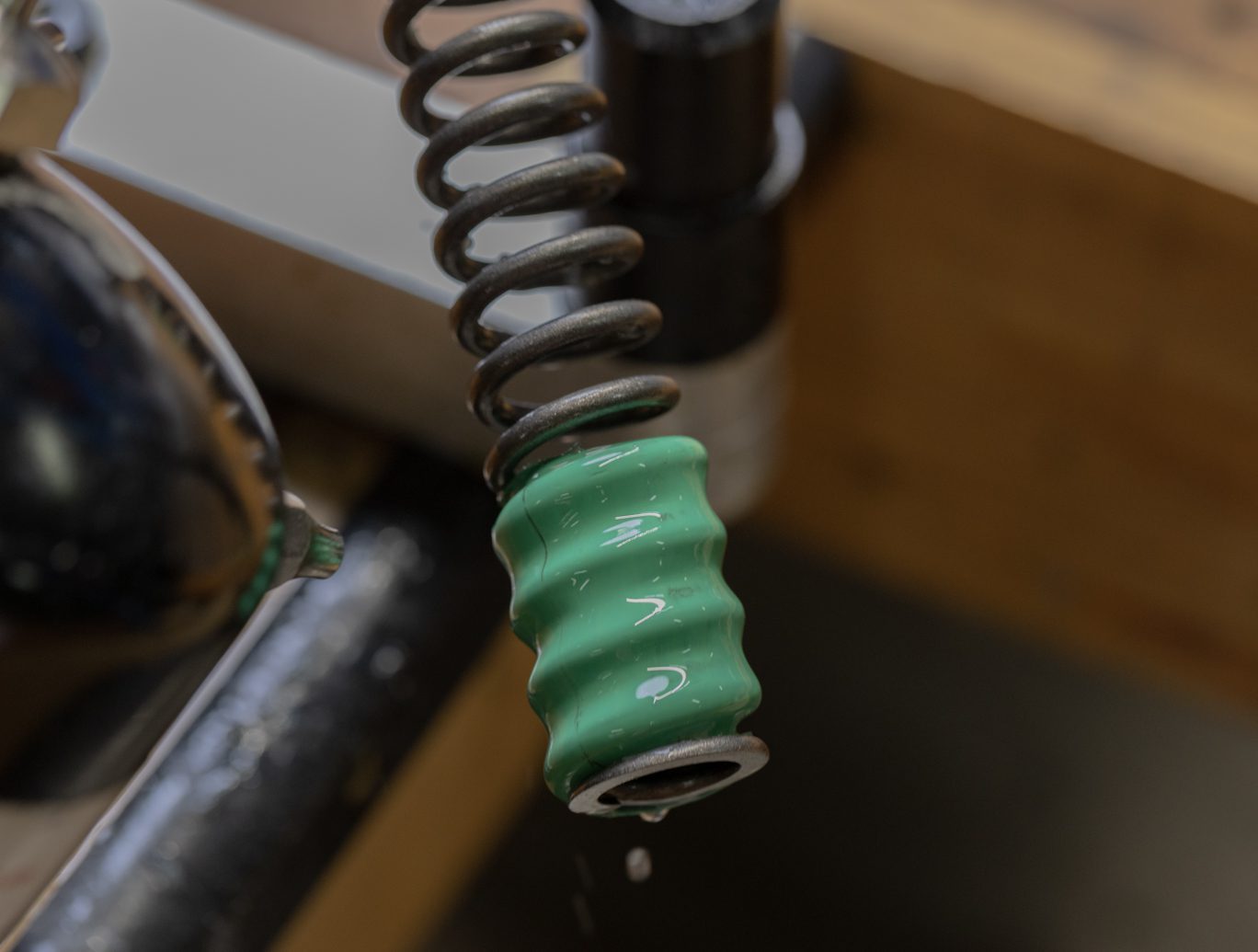
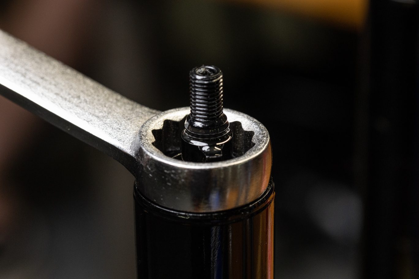
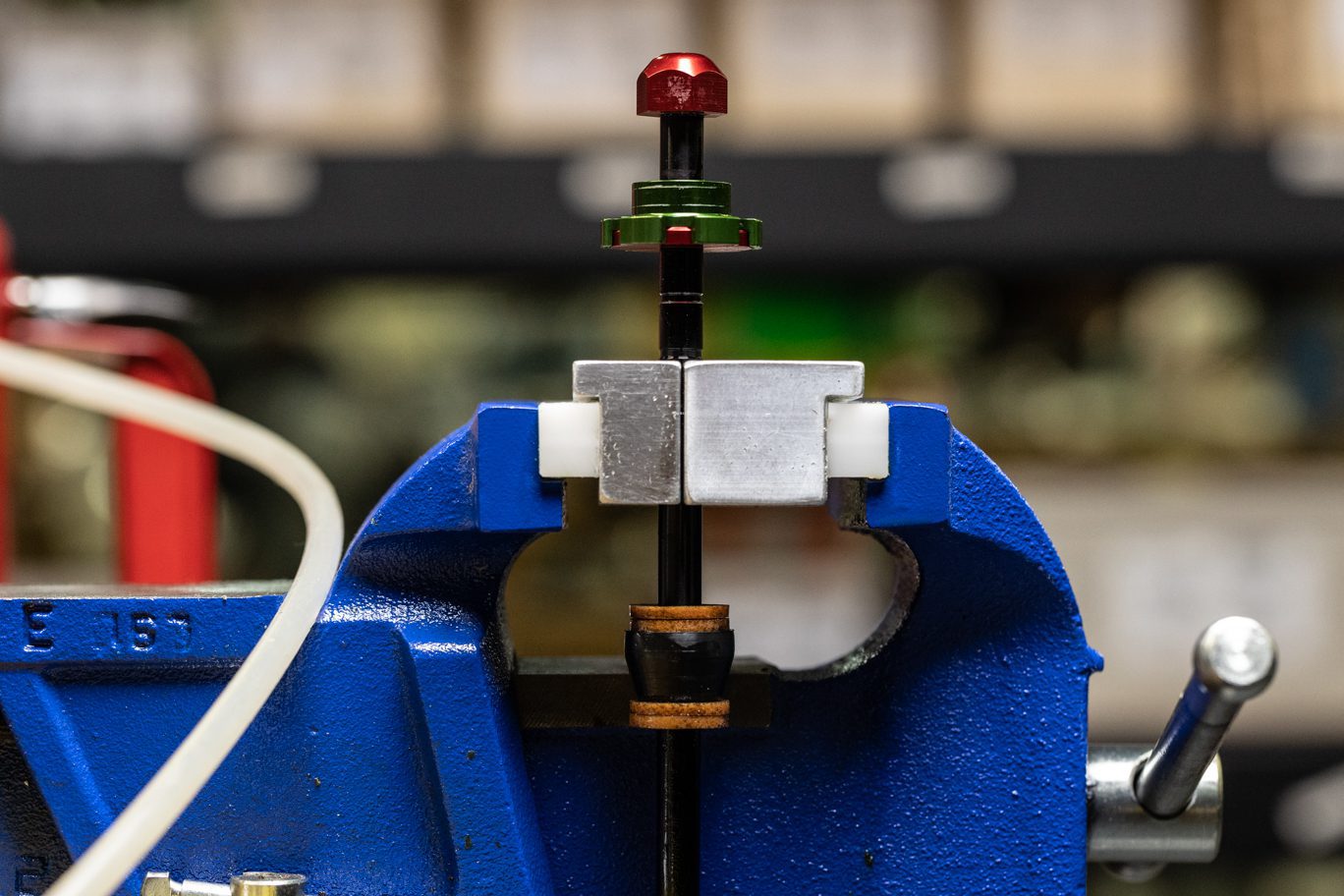
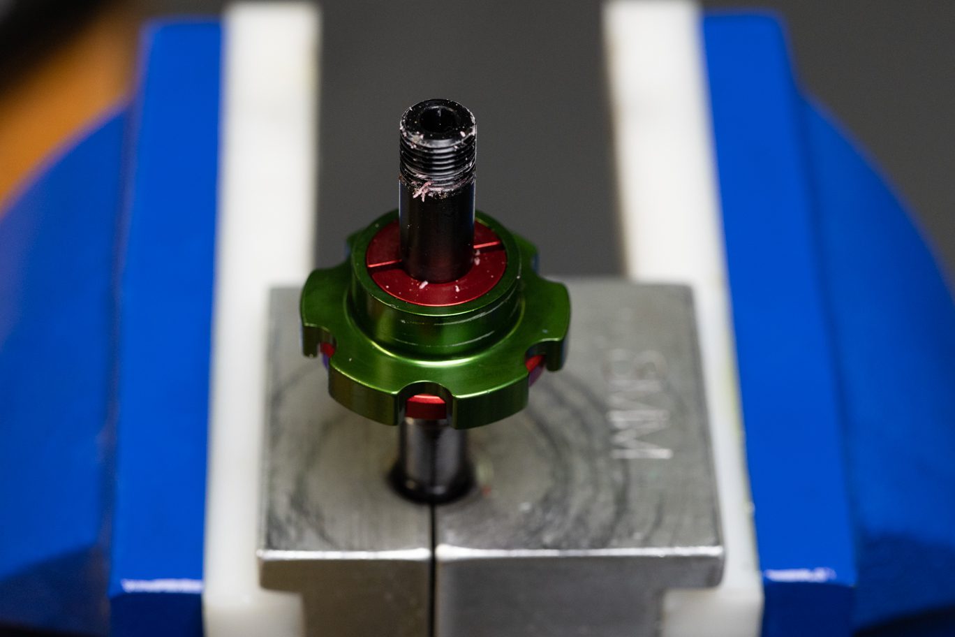
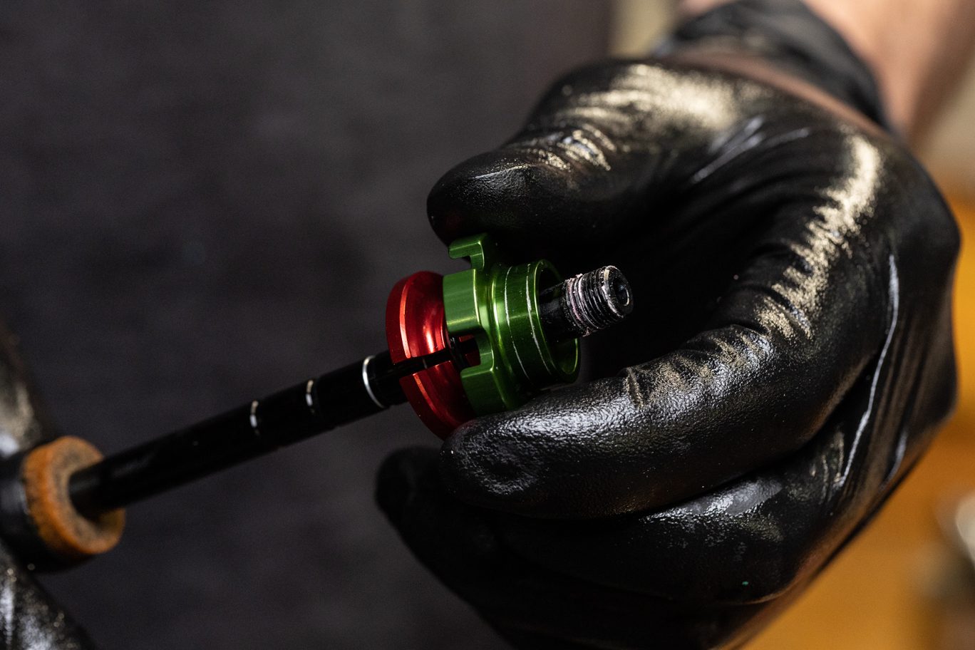
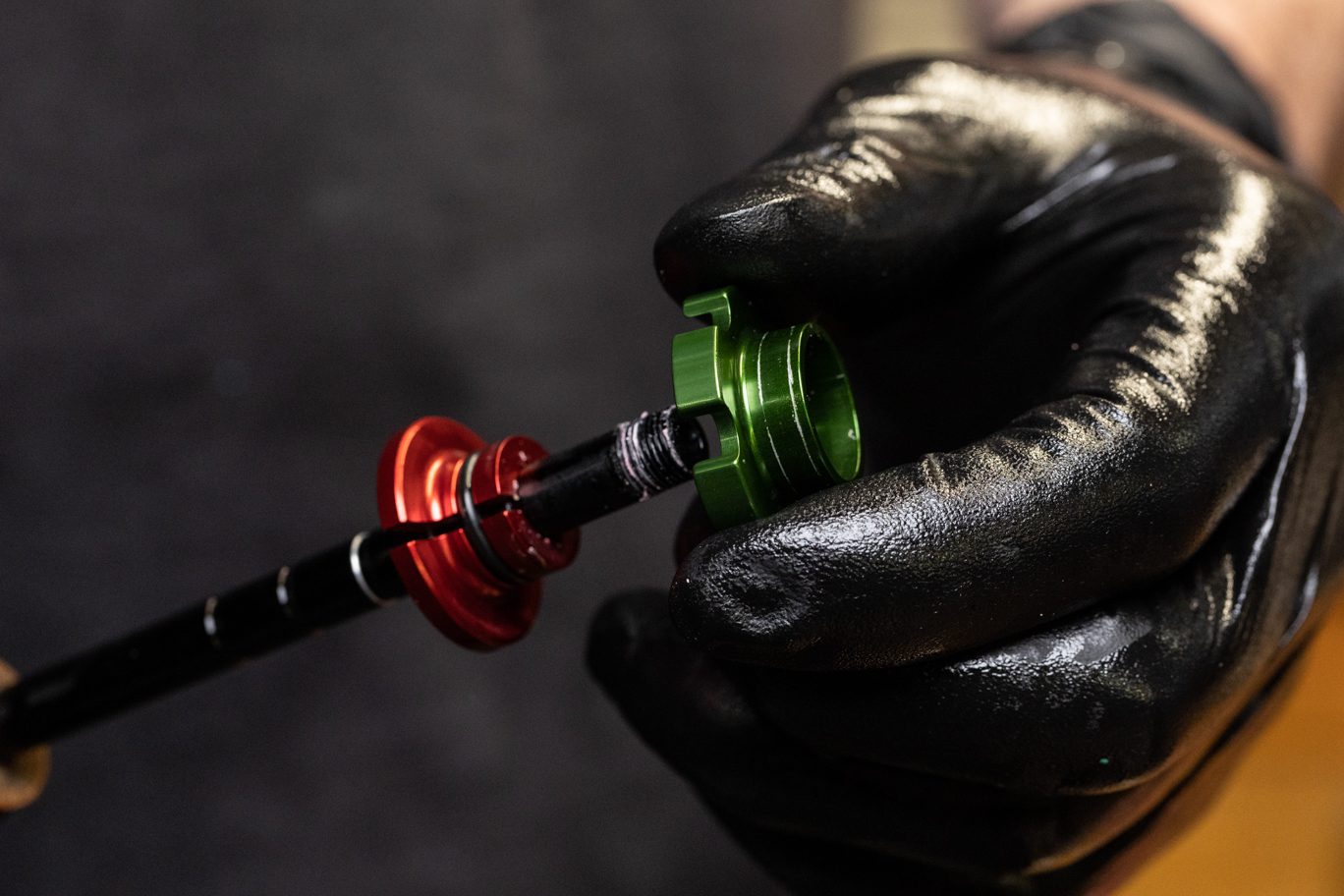
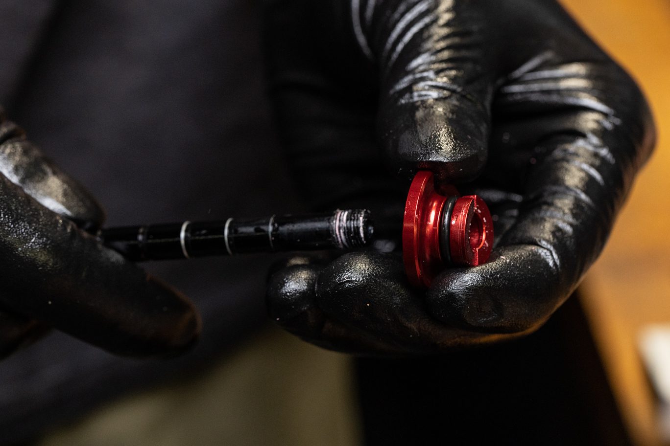
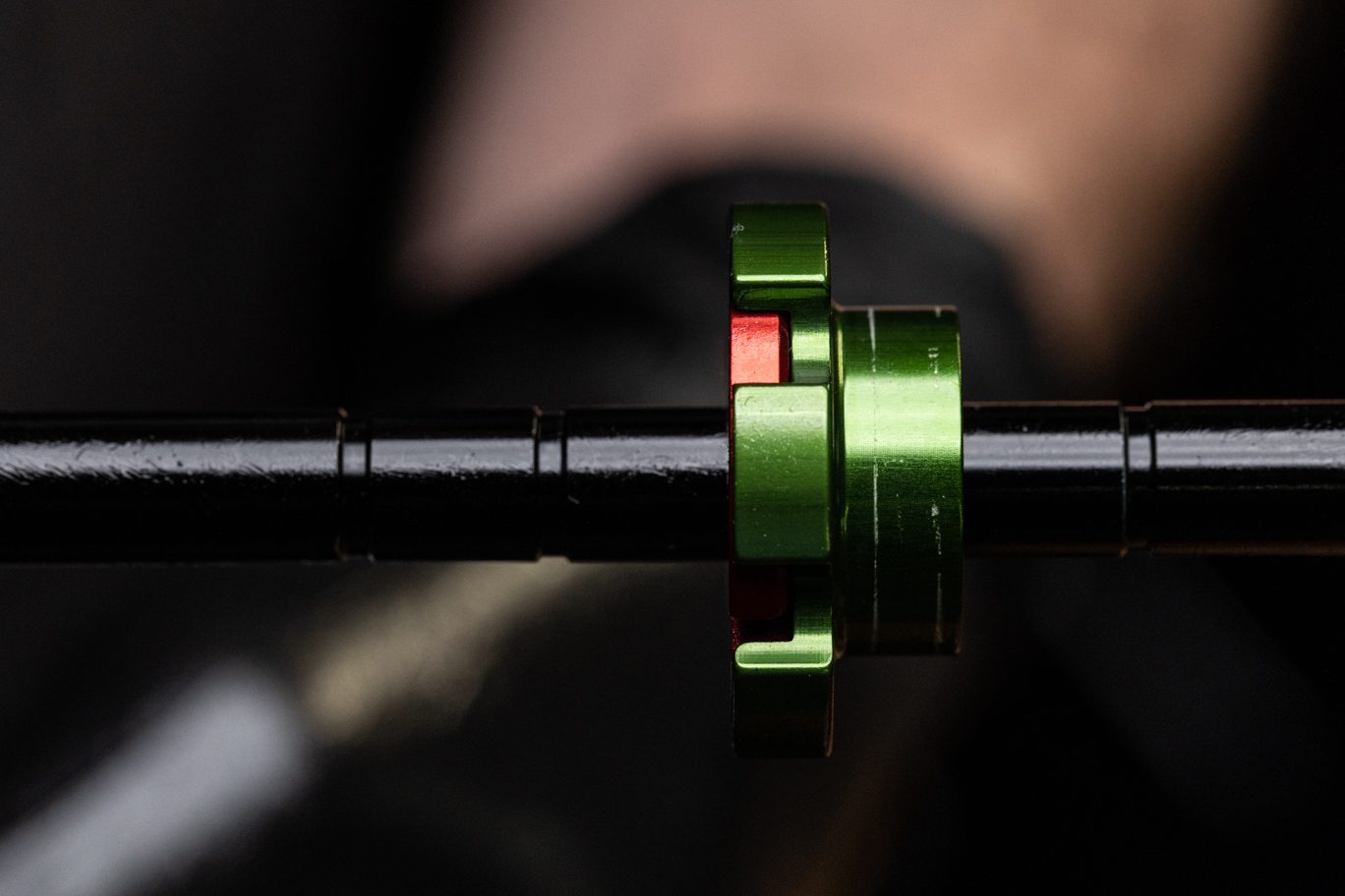
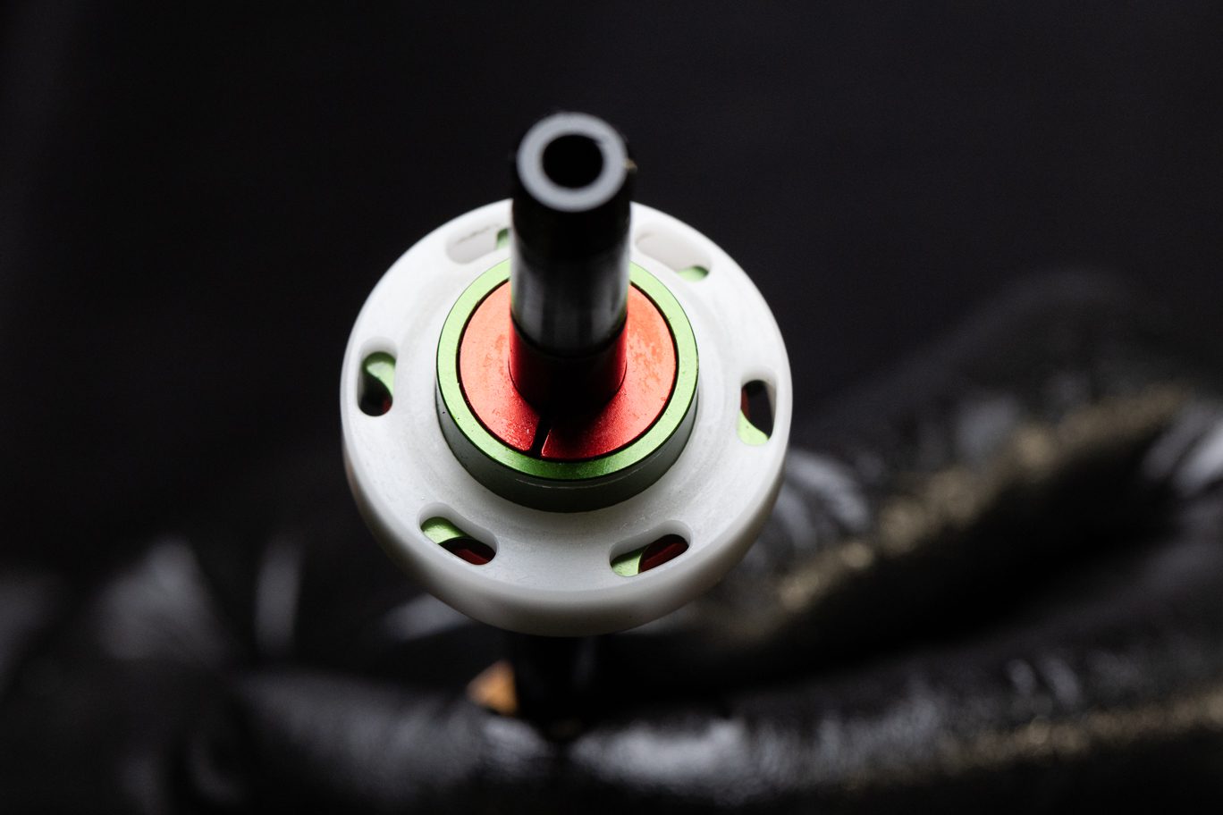
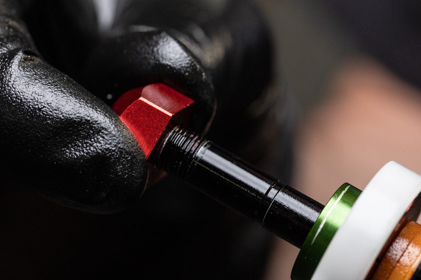
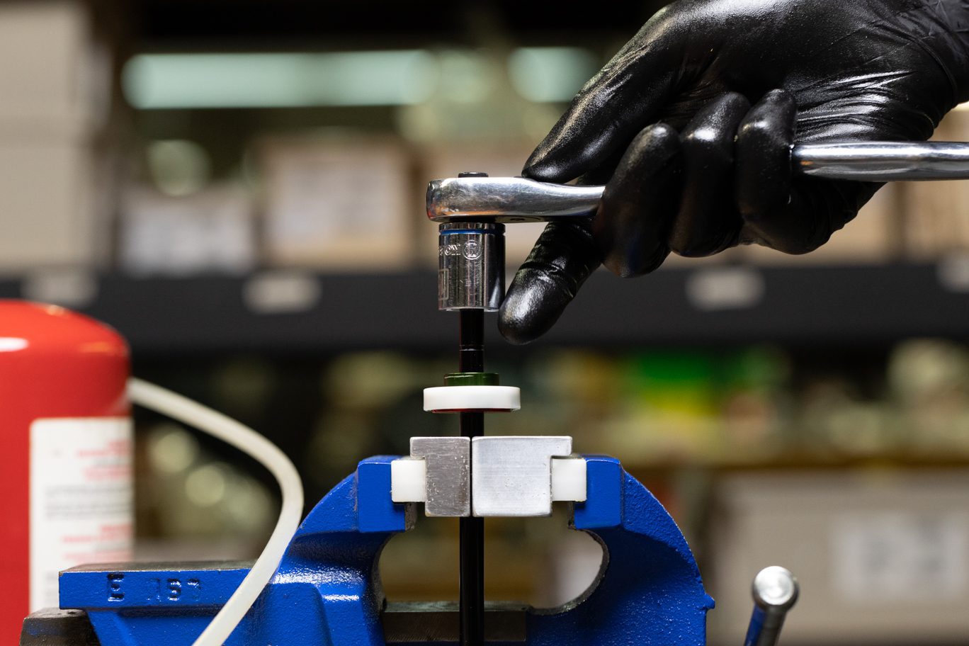
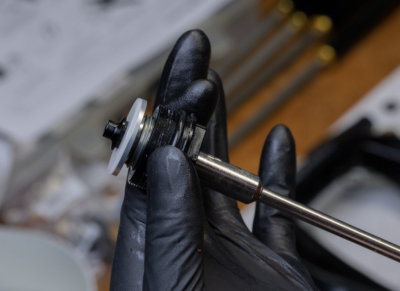
Using 8mm shaft clamp, secure shaft between spring perch and top out bumpers. Using 15mm socket, remove compression rod stop. Remove spring perch, collet, and top out bumpers as necessary.
TSB027 – Compression Rod Top Out Changes
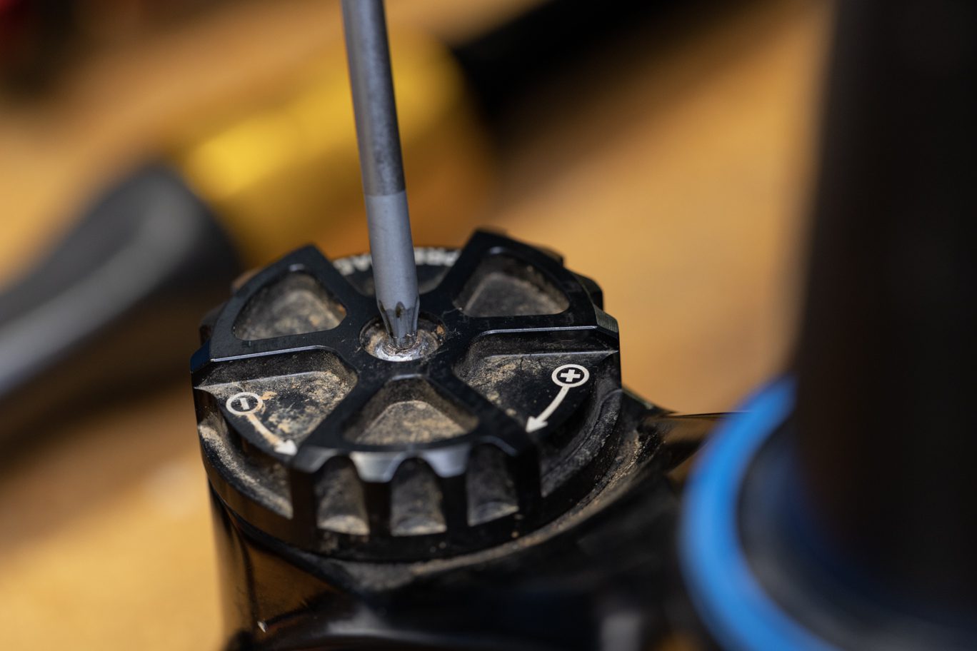
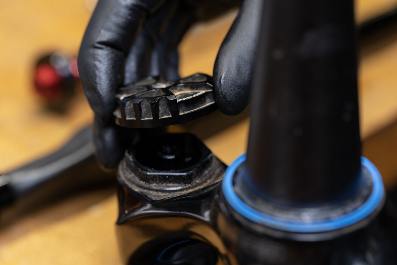
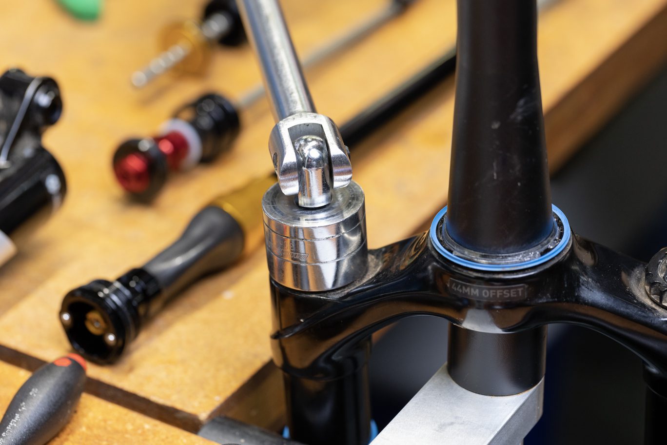
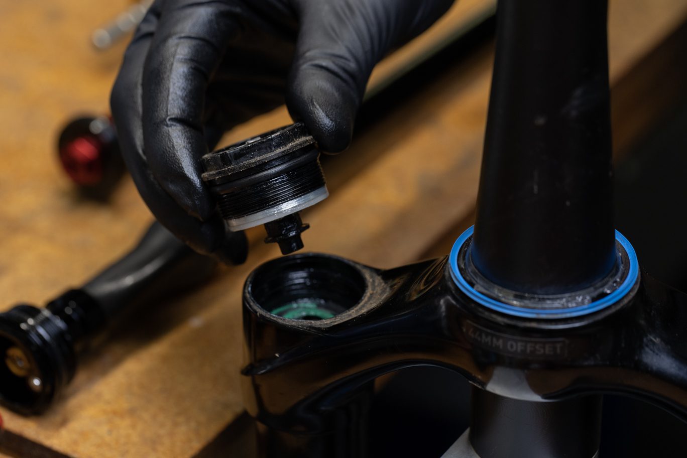
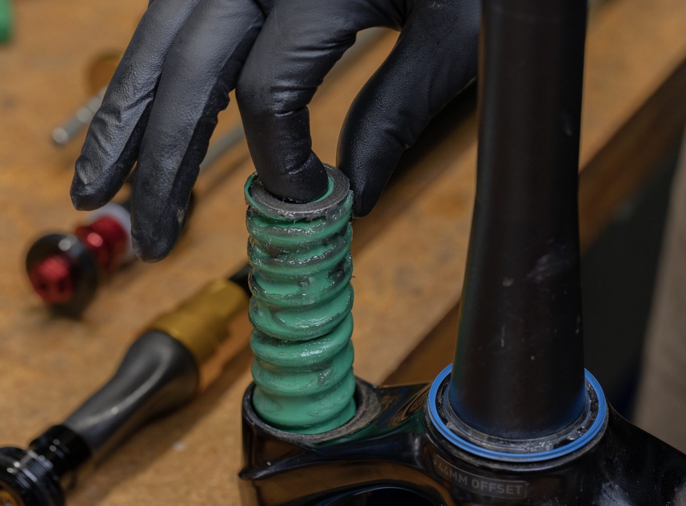
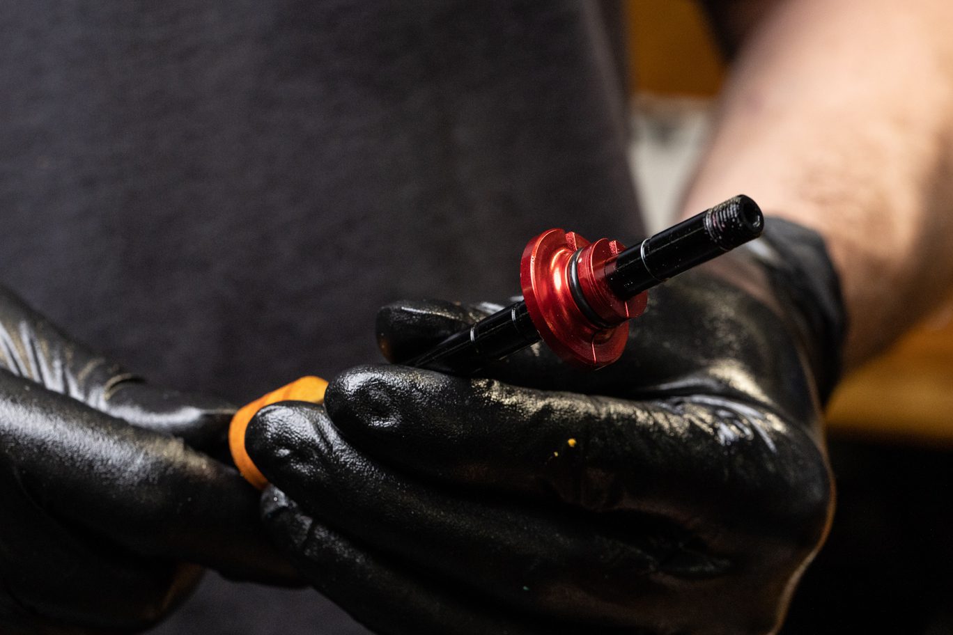
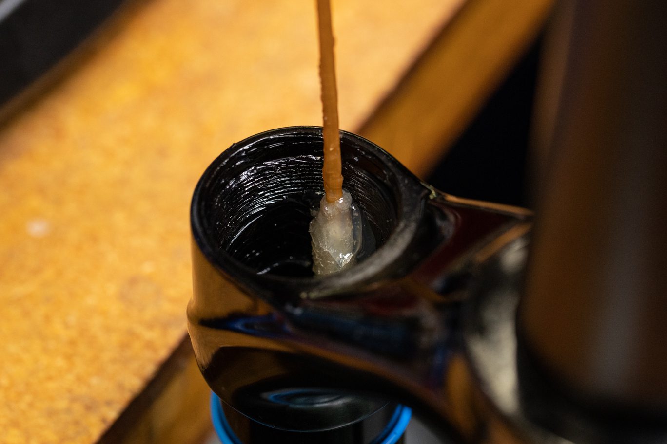
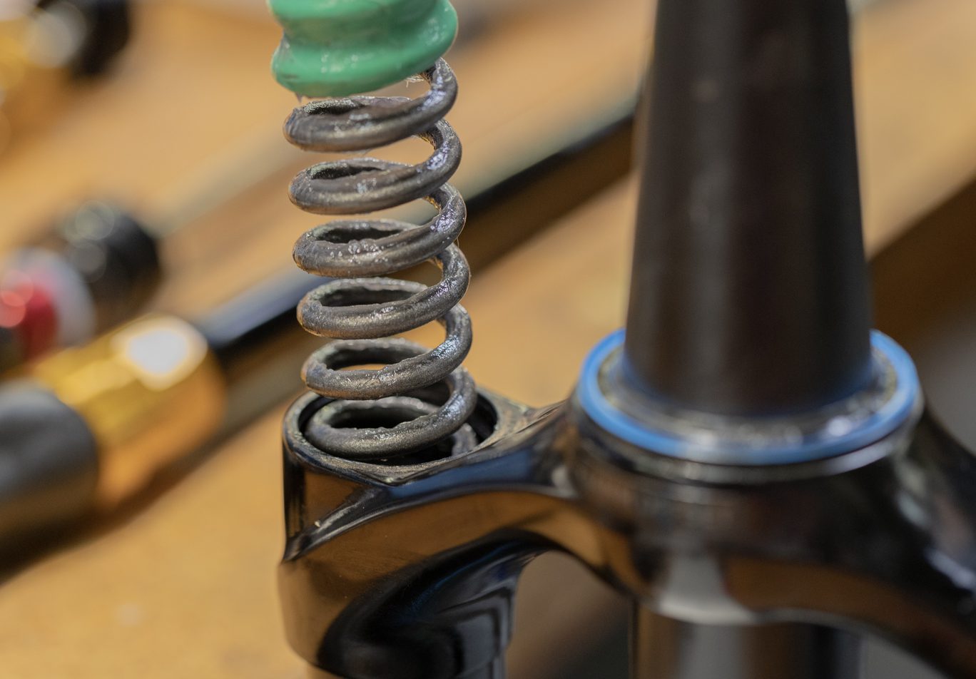
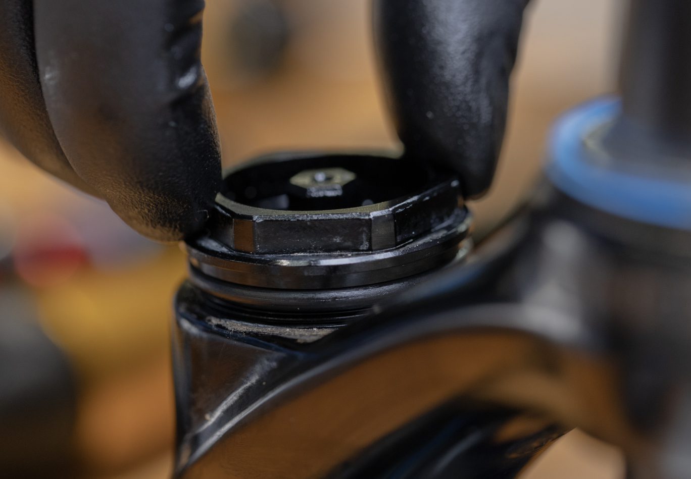
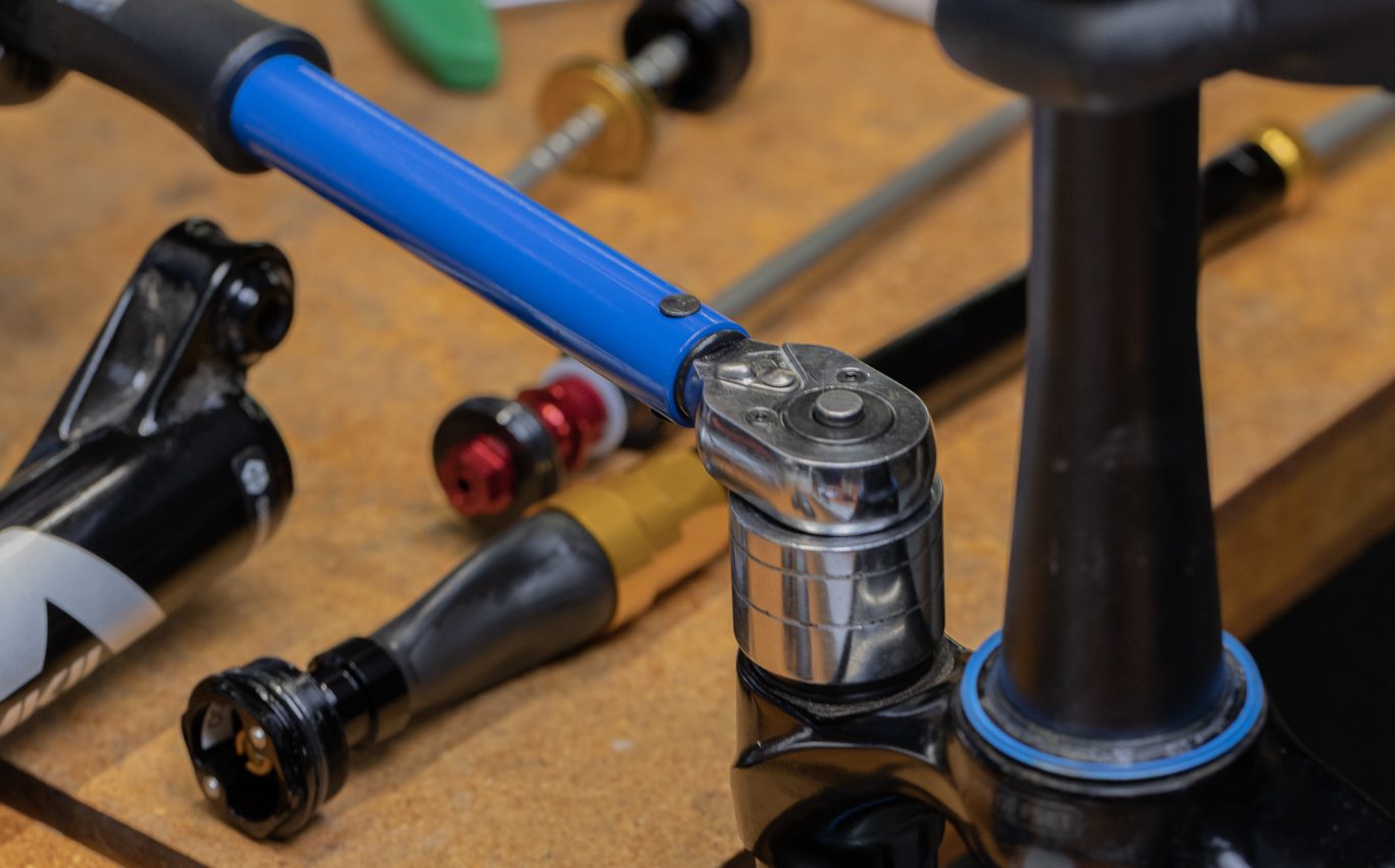
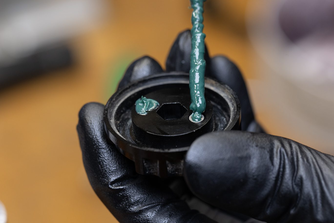
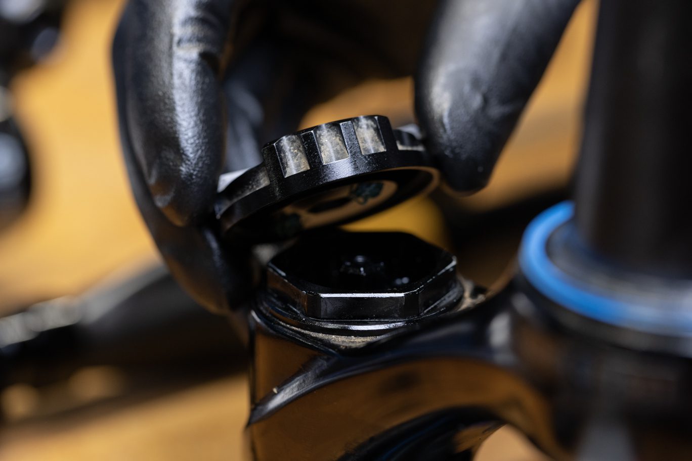
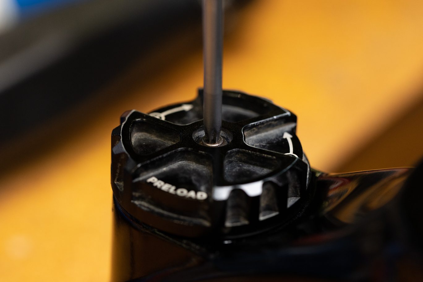
Flip CSU. Apply fresh grease to spring. Install spring back into spring side stanchion. Thoroughly clean preloader assembly and check for free movement of preloader. Apply blue Loctite (243) to threads. Install preloader assembly. Torque to 36 Nm using 30mm socket.
Upon completion of the spring side install and any damper service, install lower assembly per the 50 hour service instructions.

Monday: 10:00 am – 5:00 pm
Tuesday – Thursday: 10:00 am – 5:00 pm
Friday: 10:00 am – 5:00 pm
Saturday – Sunday: Closed