We Are Open and Have Returned to Normal Operations
Previous slide
Next slide
Mar 2022 orig., Jun 2024 rev.
Please dispose of all waste products and materials through proper channels to avoid contamination of the environment.
Any damage or issues resulting from improper service will not be covered by warranty. If you have a shock still in its original warranty period and do not wish to void your warranty, please contact an authorized Cane Creek service center.
These service instructions cover the basic service procedures using standard service kits. If your suspension requires parts beyond standard replacement parts – shaft, damper tubes, end eyes – please consult your authorized Cane Creek service center or contact us at our Cane Creek Support Center.
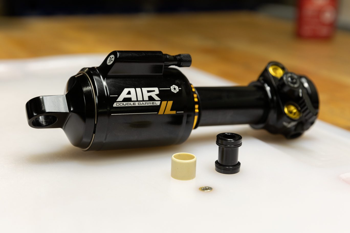
The Air IL and Coil IL as well as the Standard and Trunnion variants of both share many service steps. Some images in these instructions may not be identical to the the valve body or outer damper tube on the Air IL Standard, but that is only when the process is the same for the shock in the image and the shock on your bench.
BAD1214 – DBInline/DBair IL Damper Rebuild Kit (Standard)
BAD2279 – DBair IL Air Spring Rebuild Kit
AAD1101-01 – Keith Cradle (for standard valve body)
BCD0344 – Kitsuma/DBair/DBair IL Air Seal Head Tool
AAD1193 – Air Seal Head Bullet – Red (or original AAD1182 – Air Seal Head Bullet – Green)
BAD1459 – Air Piston Funnel
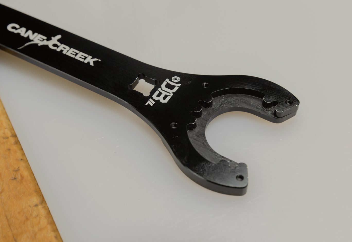
BAD1032 – Gland Nut Wrench
BAD1174 – Oil Seal Head Pin Spanner Wrench
BAD1268 – Inline – Oil Fill Needle Adaptor
DBT016 – DB Gas Fill Needle
AAD0555 – 8mm & 9.5mm Shaft Clamp
BAD1273 – Inner Damper Tube Install Tool (if replacing inner damper tube)
Torque & Loctite Chart
| Part | Torque Spec | Loctite Spec |
| Shaft Bolt | 5 Nm | 243 (Blue) |
| TSN | 0.6 Nm | 668 (Green) |
| Spool Valve | 0.16 Nm | 243 (Blue) |
| Inner Damper Tube | 17 Nm | 263 (Red) |
| Oil Seal Head | 15 Nm | None |
| Gland Nut | 52 Nm | 243 (Blue) |
| Climb Switch Screw | 0.16 Nm | 243 (Blue) |
| Air Piston Screws | 3.2 Nm | 243 (Blue) |
| End Eye | 4.8 Nm | 243 (Blue) |
| Inner Air Can/Air Seal Head | 22.6 Nm | None (PolyLube) |
Oil Chart
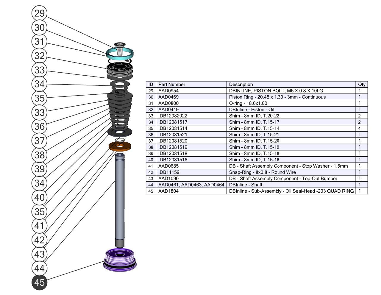
| Oil Location | Oil Type | Oil Amount |
| Air Can | Royal Purple 10w-30 | 5 mL |
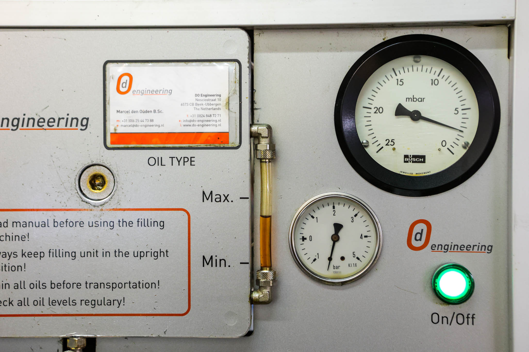
| Damper Fill | Motorex 4wt Racing Fork Oil | Fill to 3 Bars |
Nitrogen Chart
| Nitrogen Location | Nitrogen Pressure |
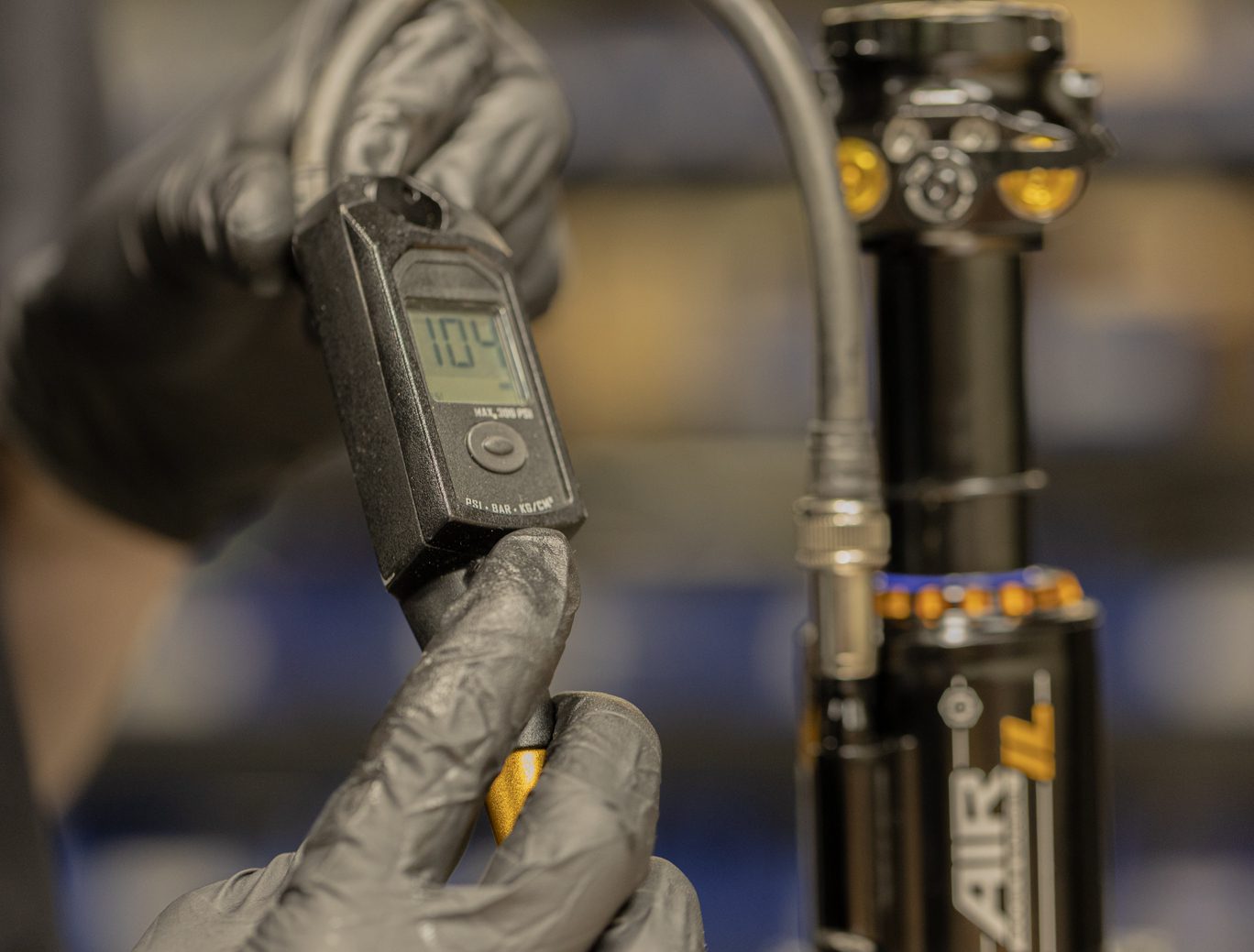
| Valve Body | 11-12 Bars |
Review all related TSBs before performing any service.
No Air IL specific TSBs at this time.
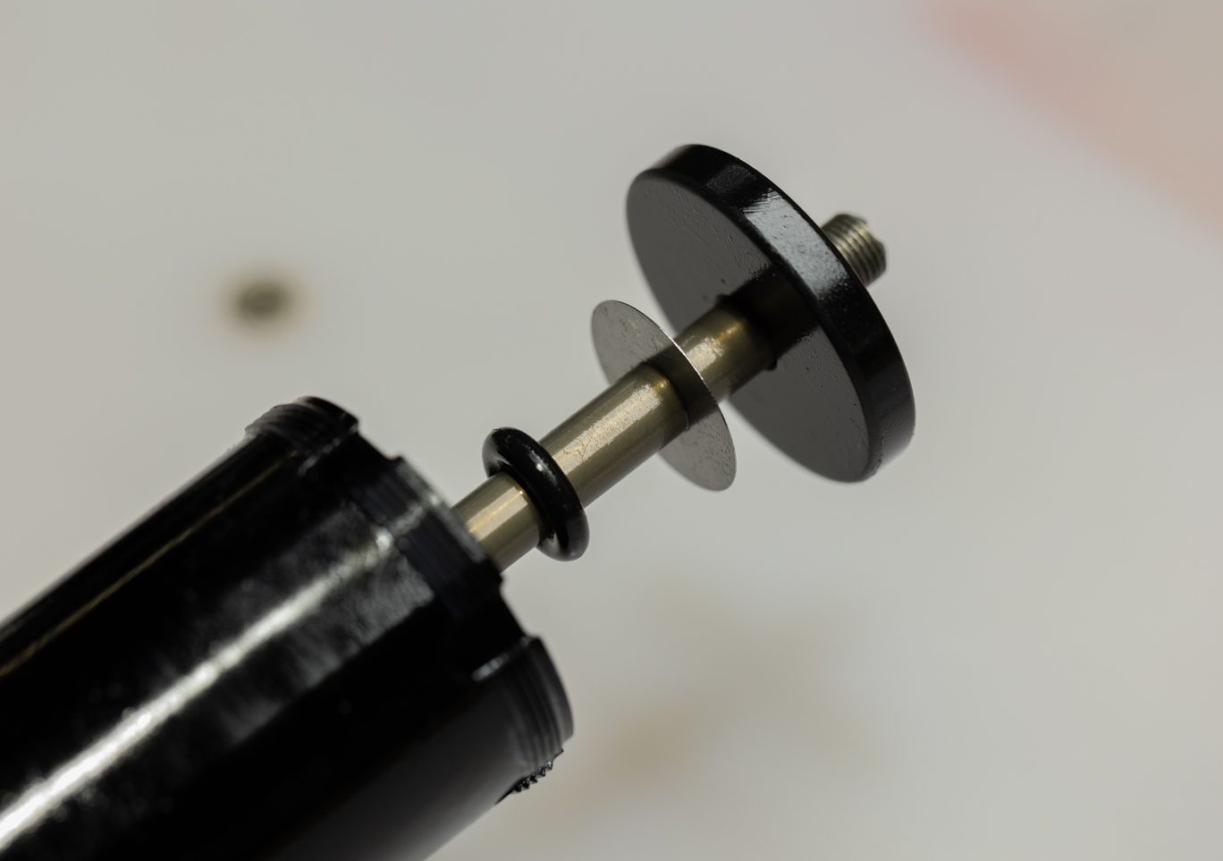
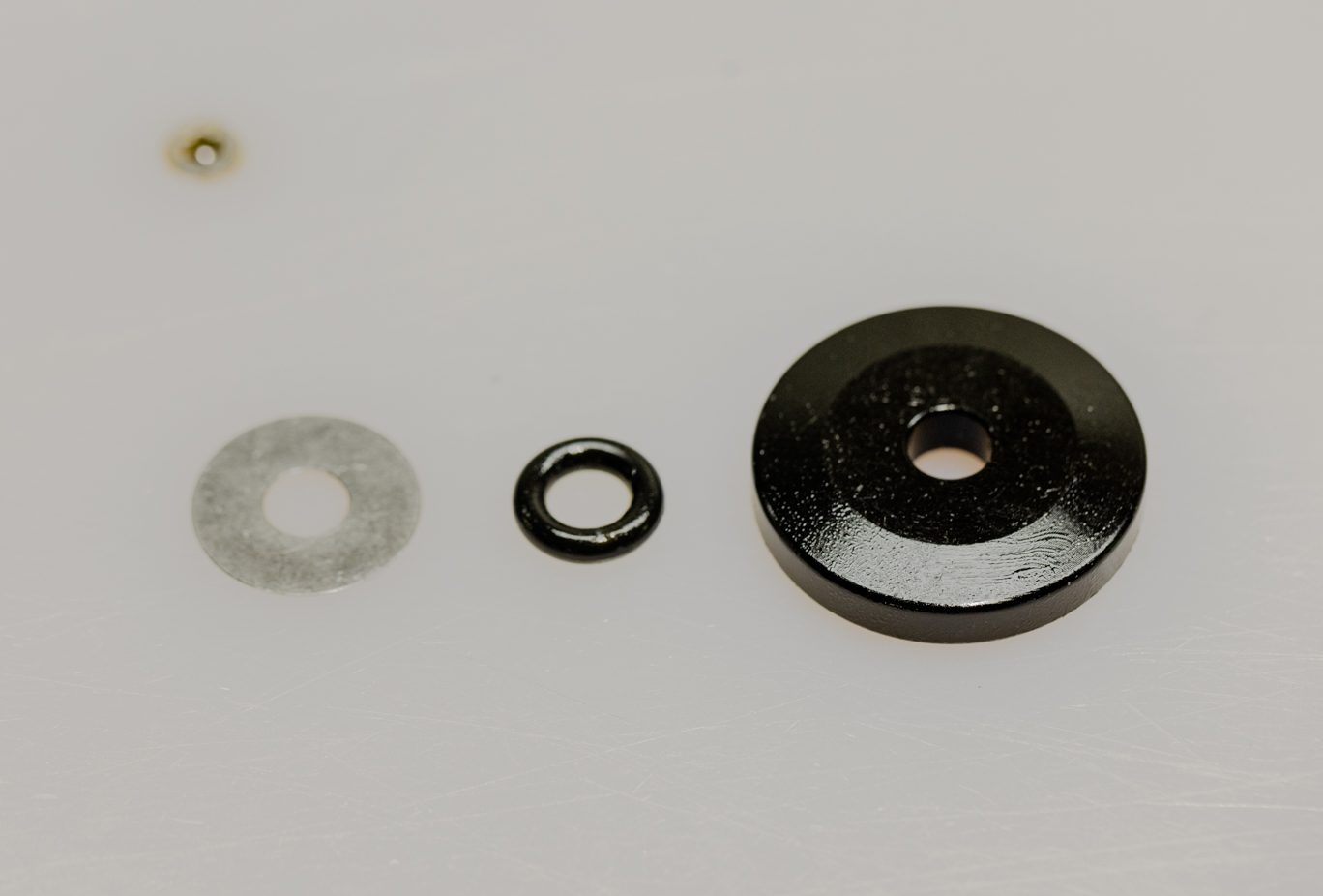
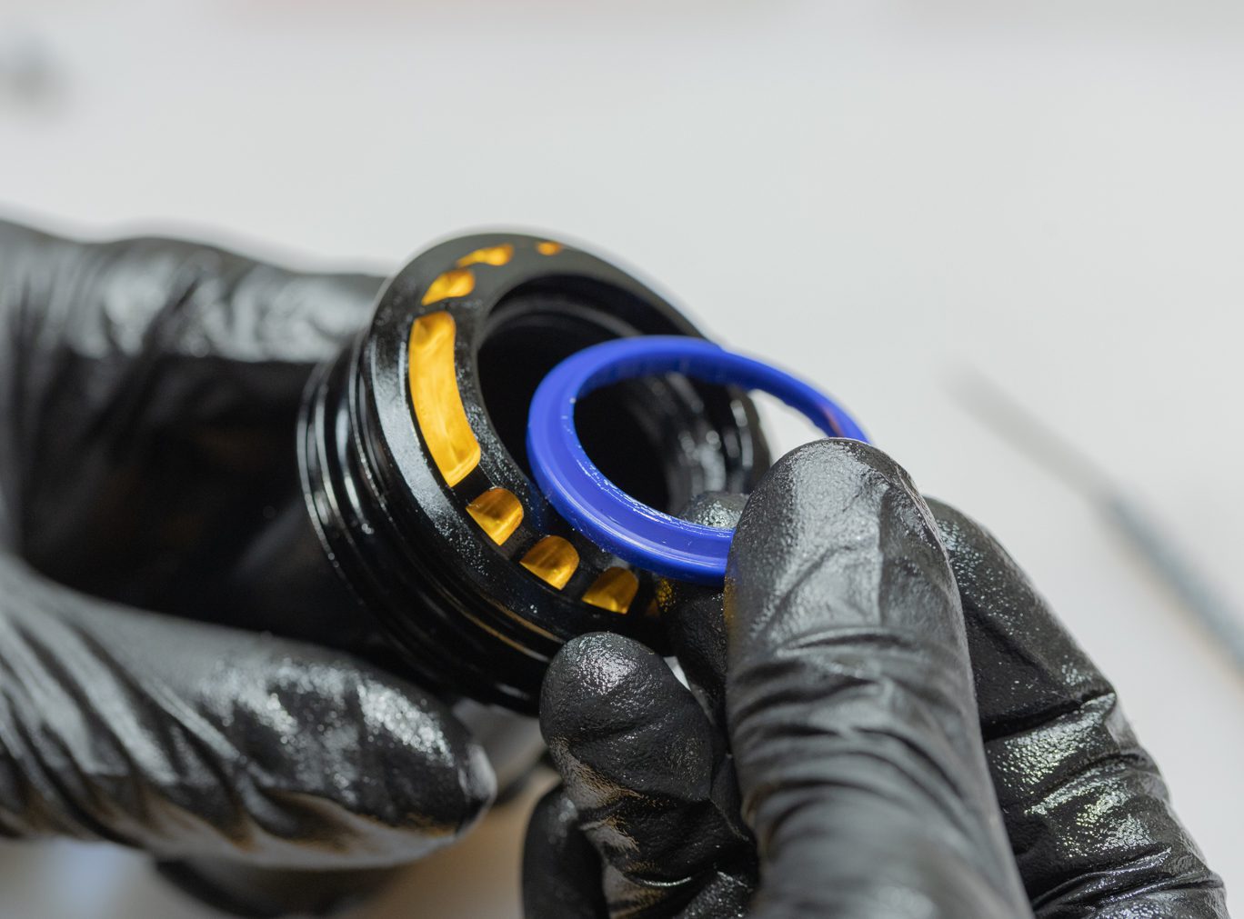
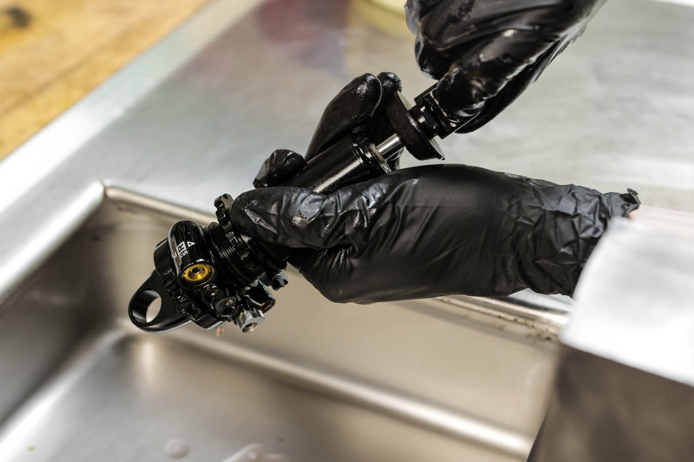
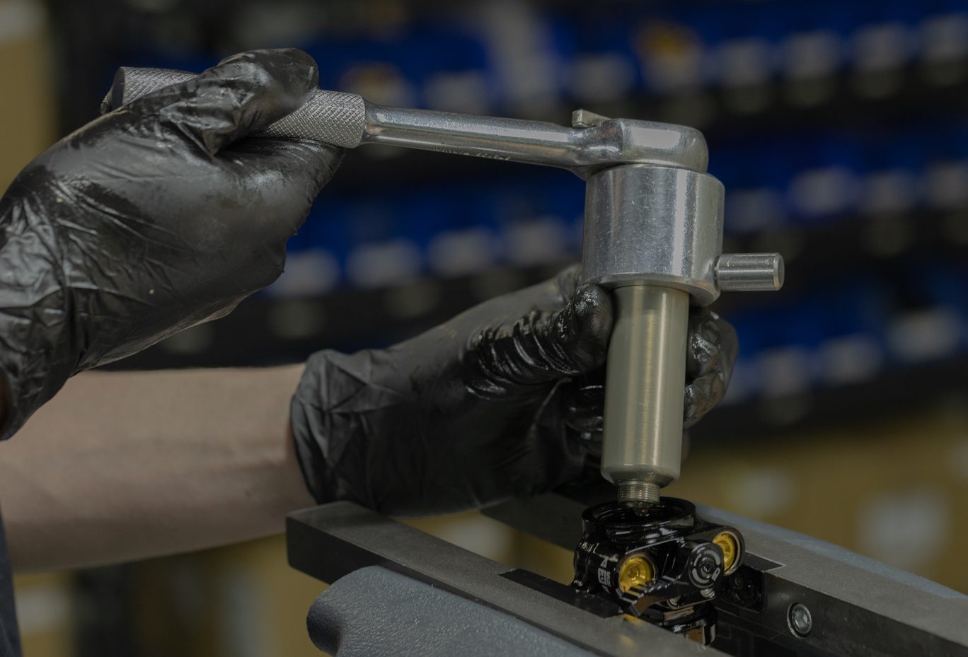
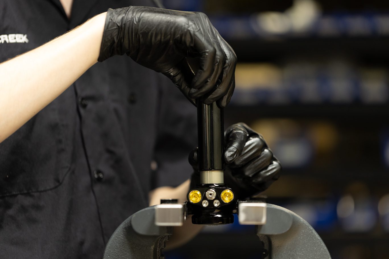
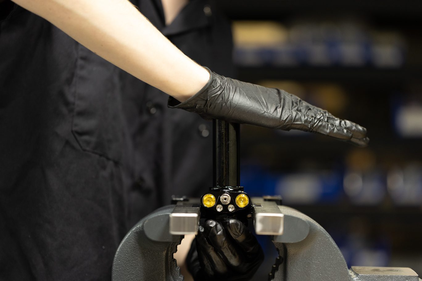
Slide inner air can up shock body to expose shaft. Clamp shaft in 8mm shaft clamp with end eye up. Remove end eye using 1/2″ crows foot. Pinch & remove then discard inner can o-ring and stop shim from end eye. Remove any stroke reduction spacer, shim and bottom out bumper.
Always use extreme caution when using a pick in this step or others to avoid scratching metal parts. Failure to do this can create scratches in the o-ring glands which cause leak paths for oil or gas. When possible, pinch and remove o-rings rather than using a pick.
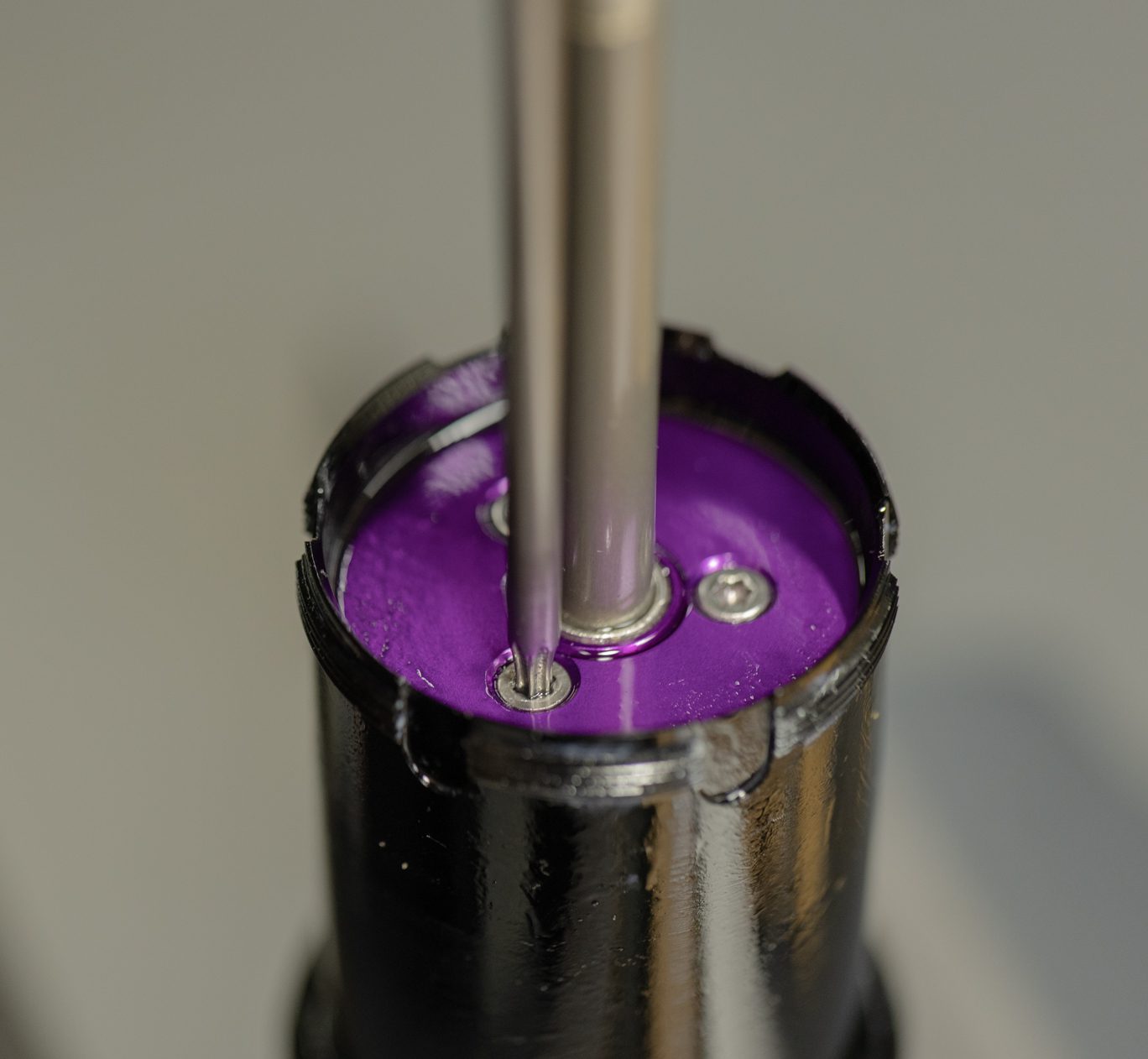
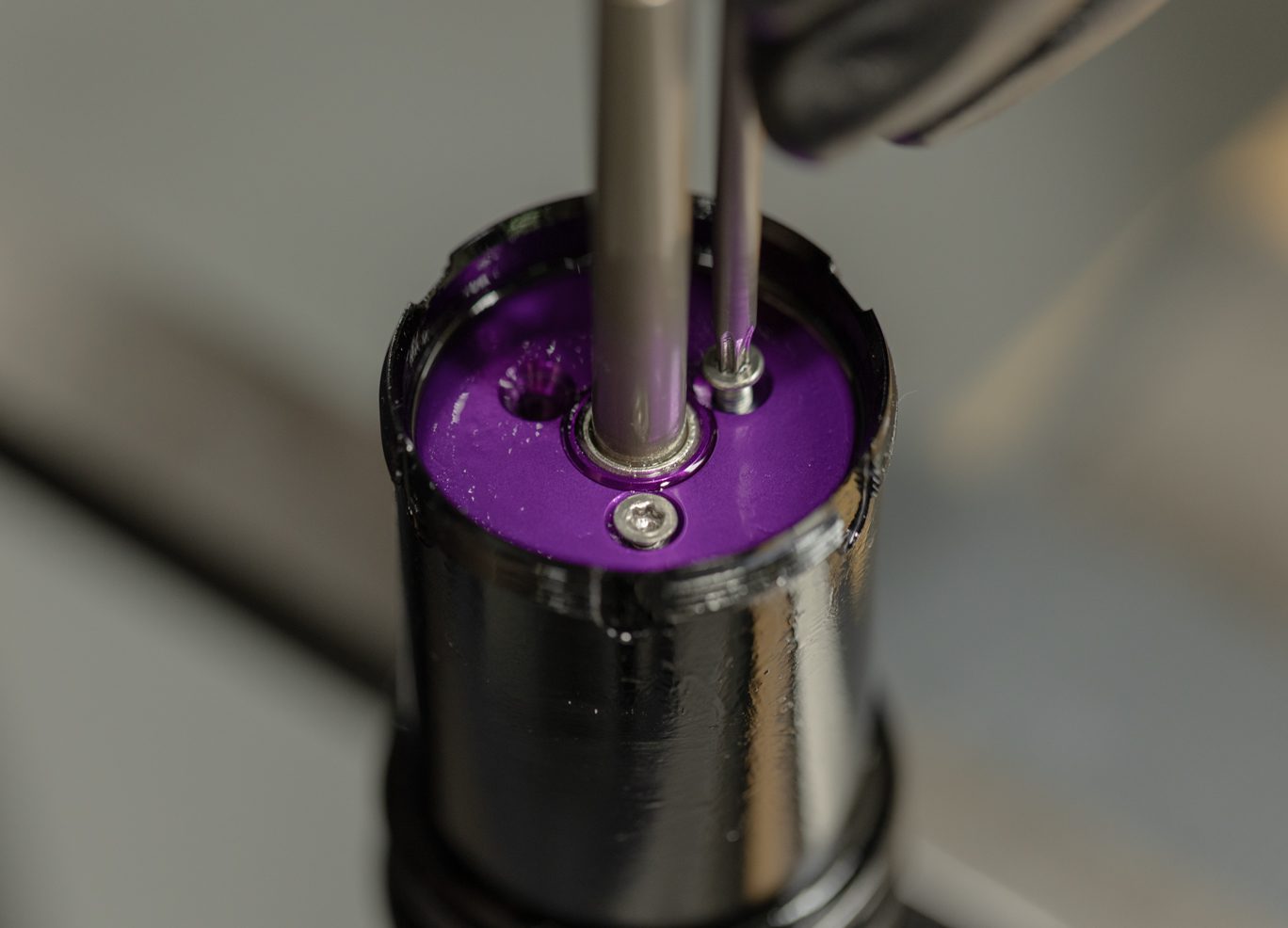
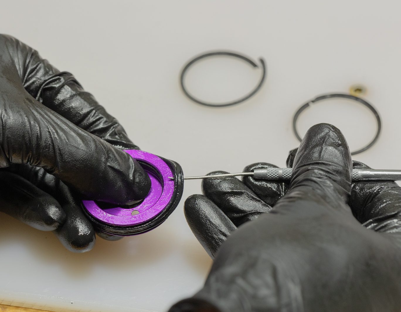
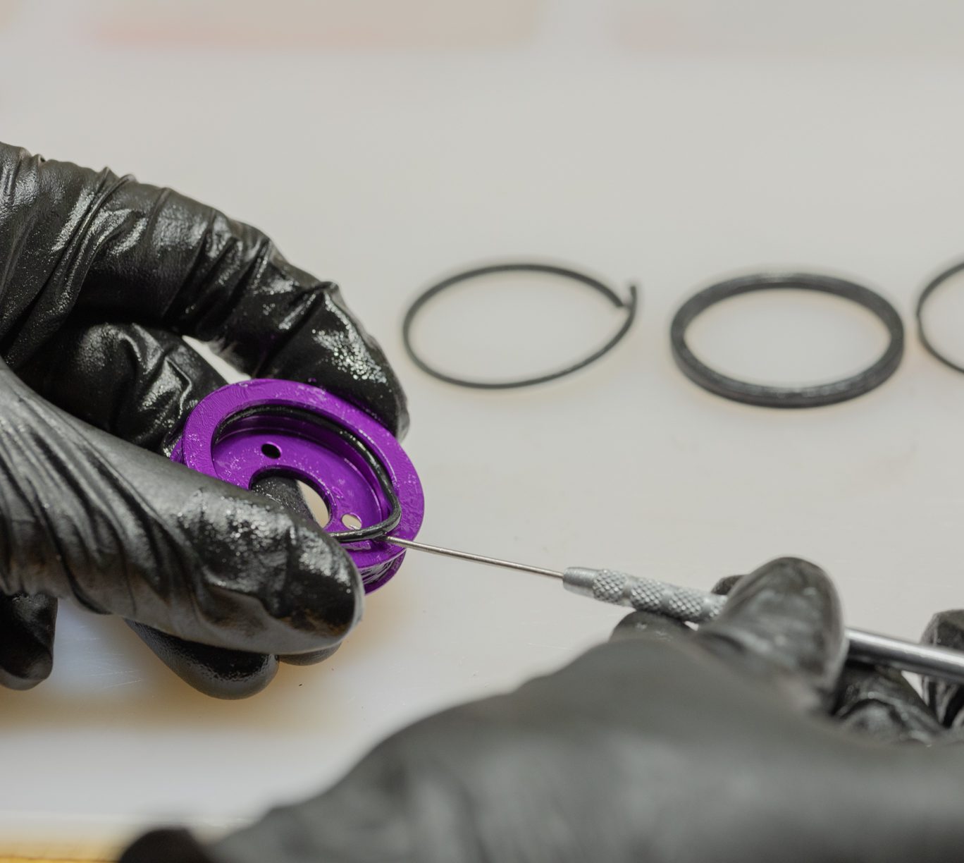
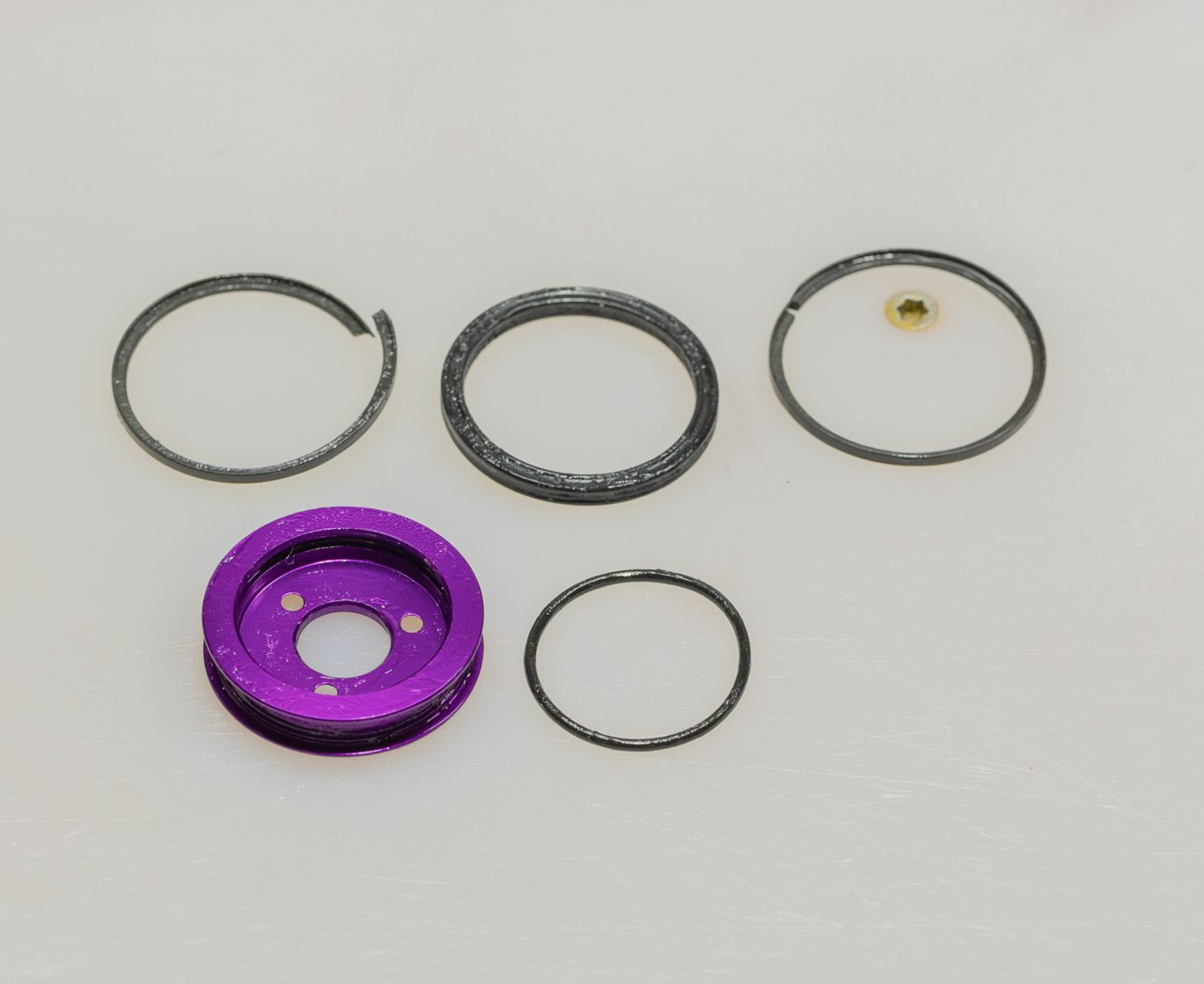
Using T10 loosen and slowly remove all 3 air piston screws. Use caution as this will release any air trapped in negative chamber. Pull up on inner air can to remove inner air can and piston. Press piston out of inner air can. Remove 2 L-back up rings, quad ring and interior o-ring from piston.
***Use caution as nitrogen is pressurized.***
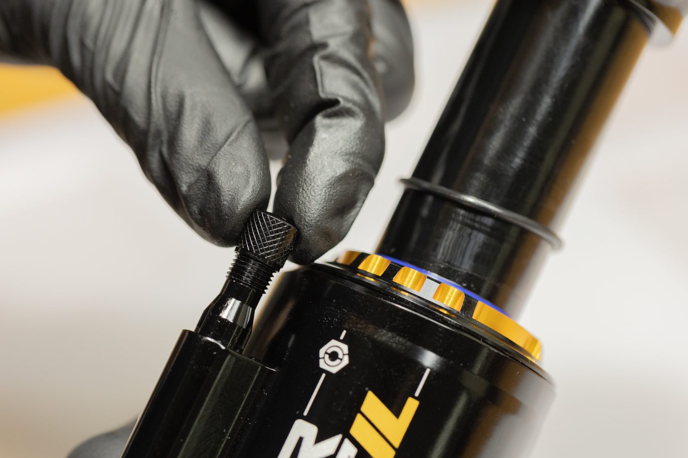
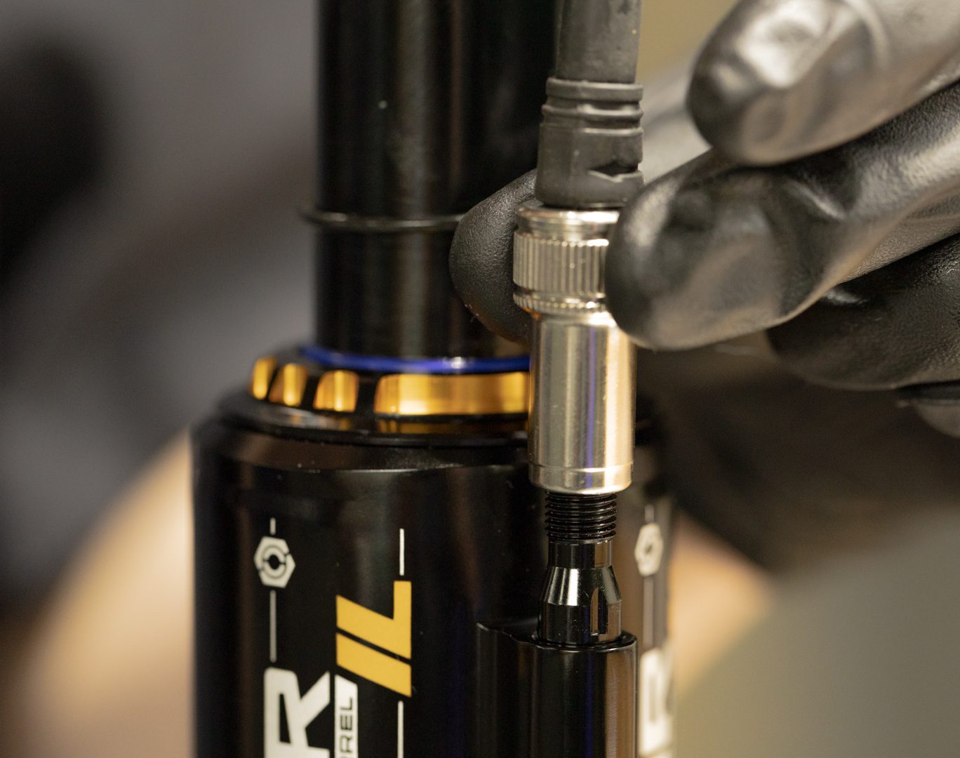
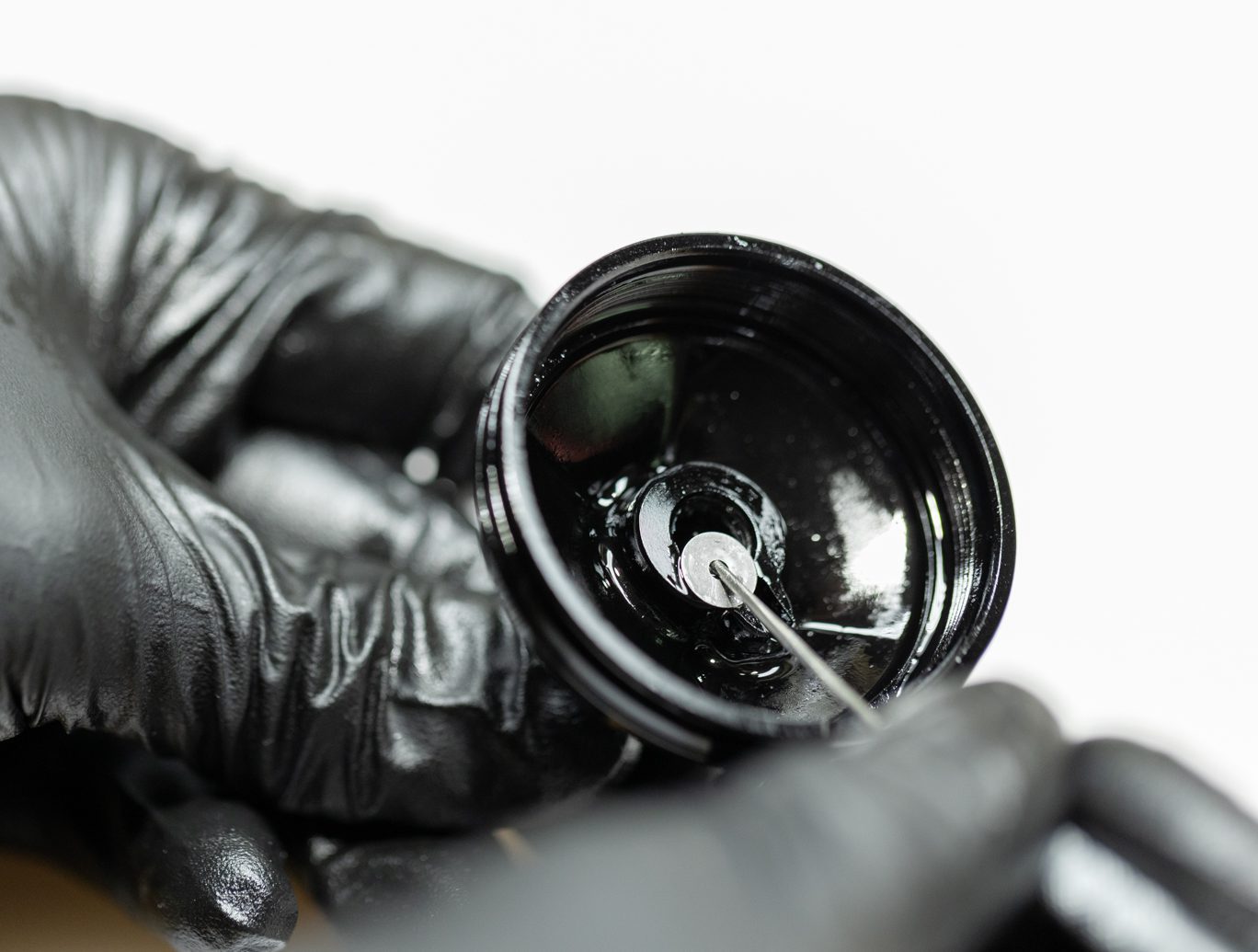
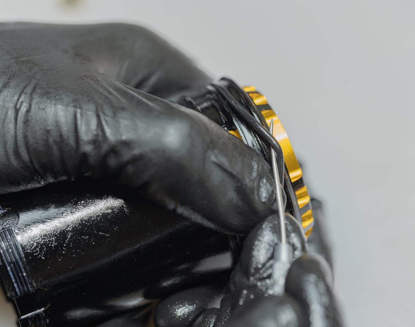
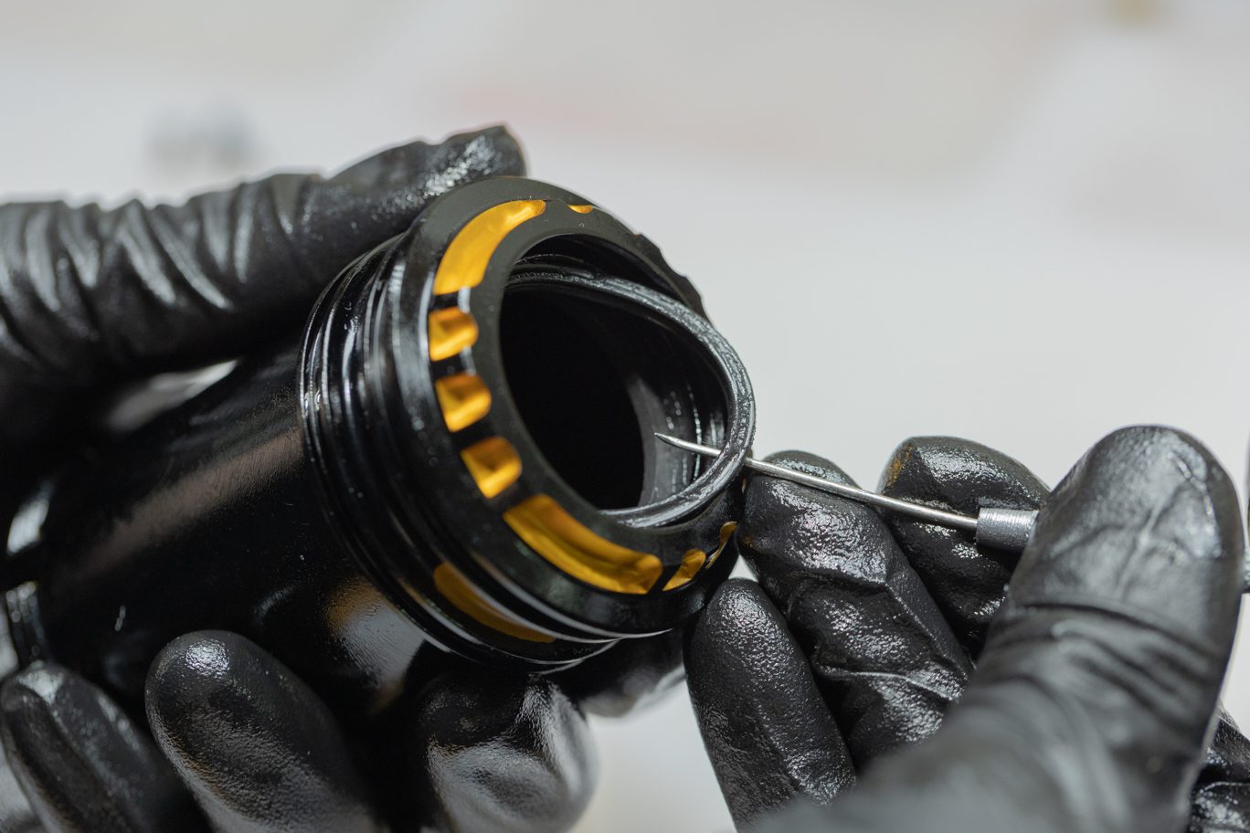
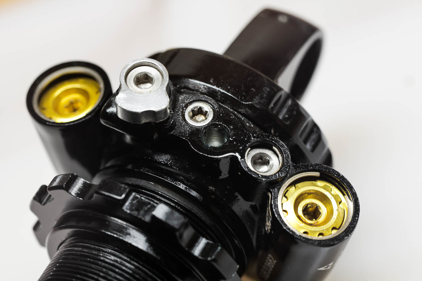
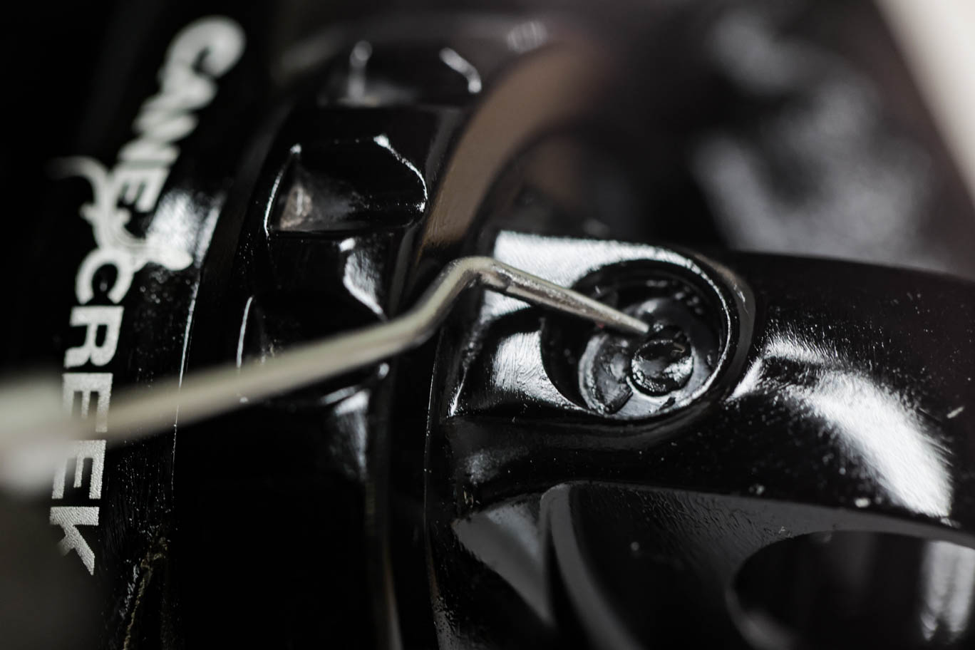
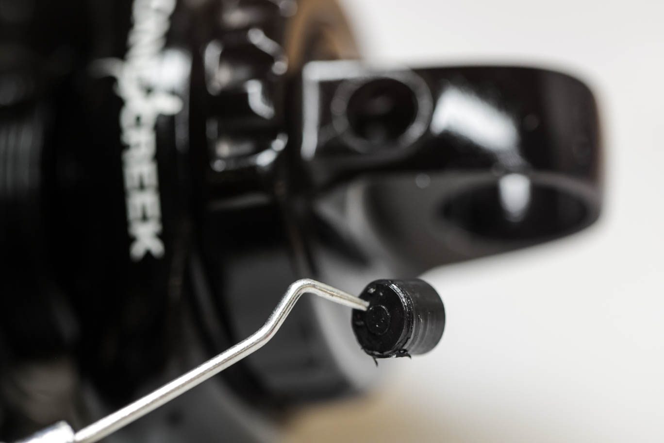
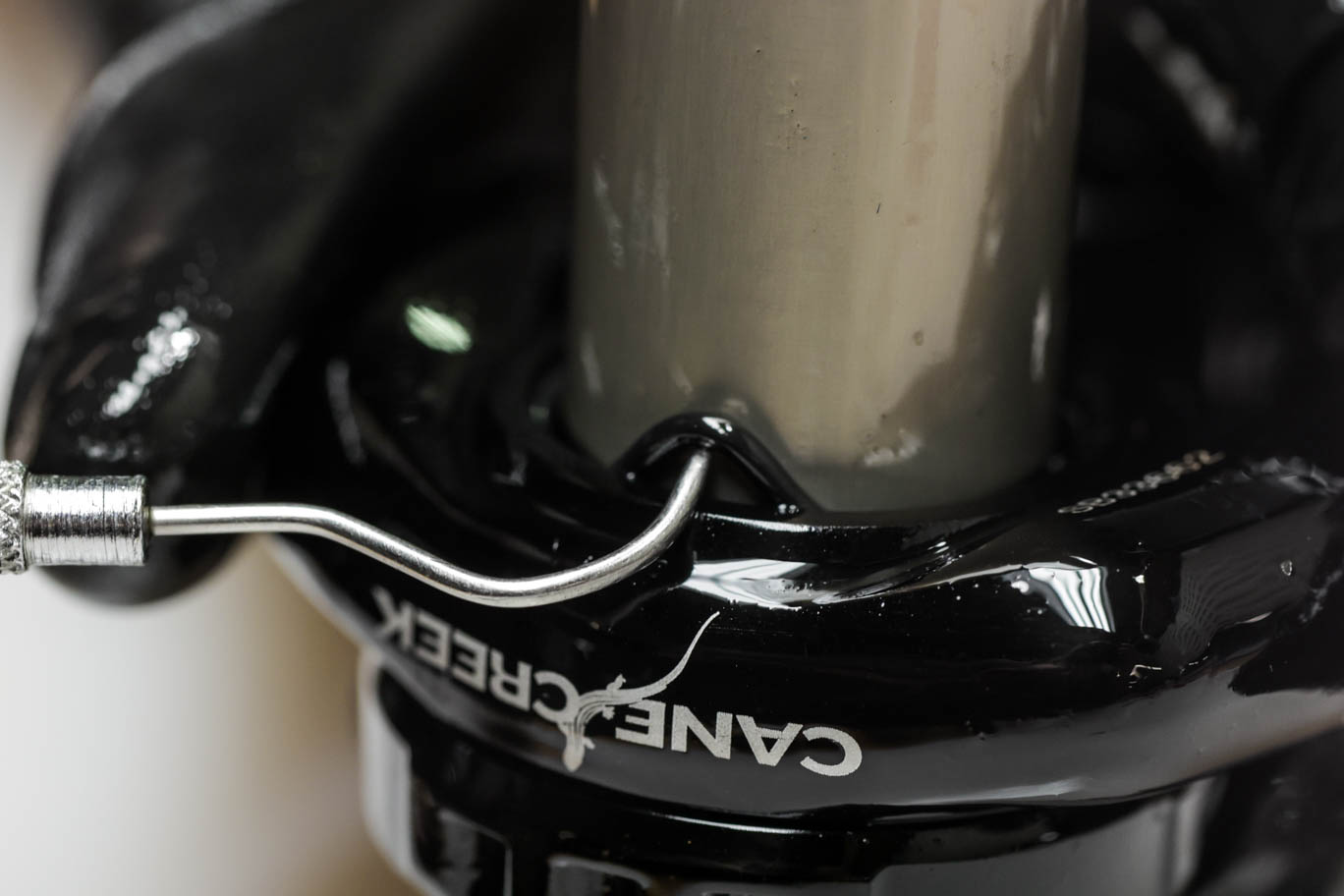
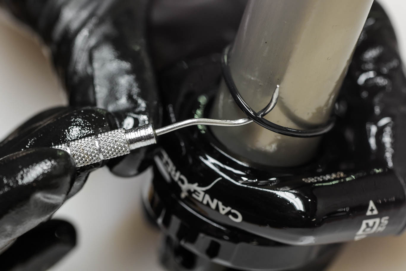
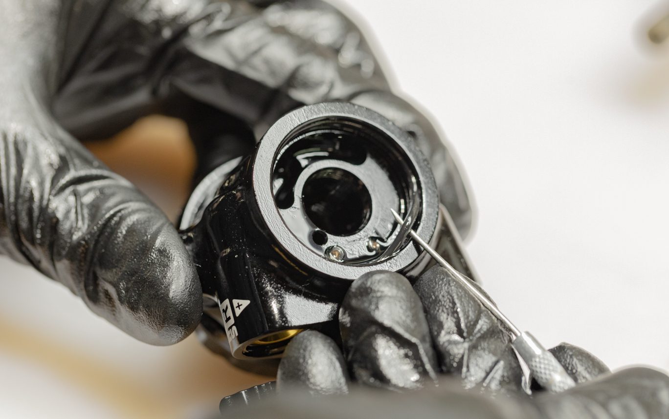
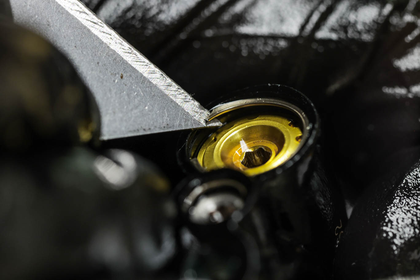
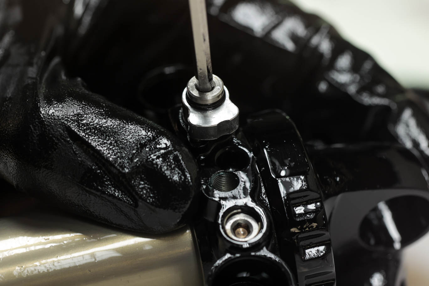
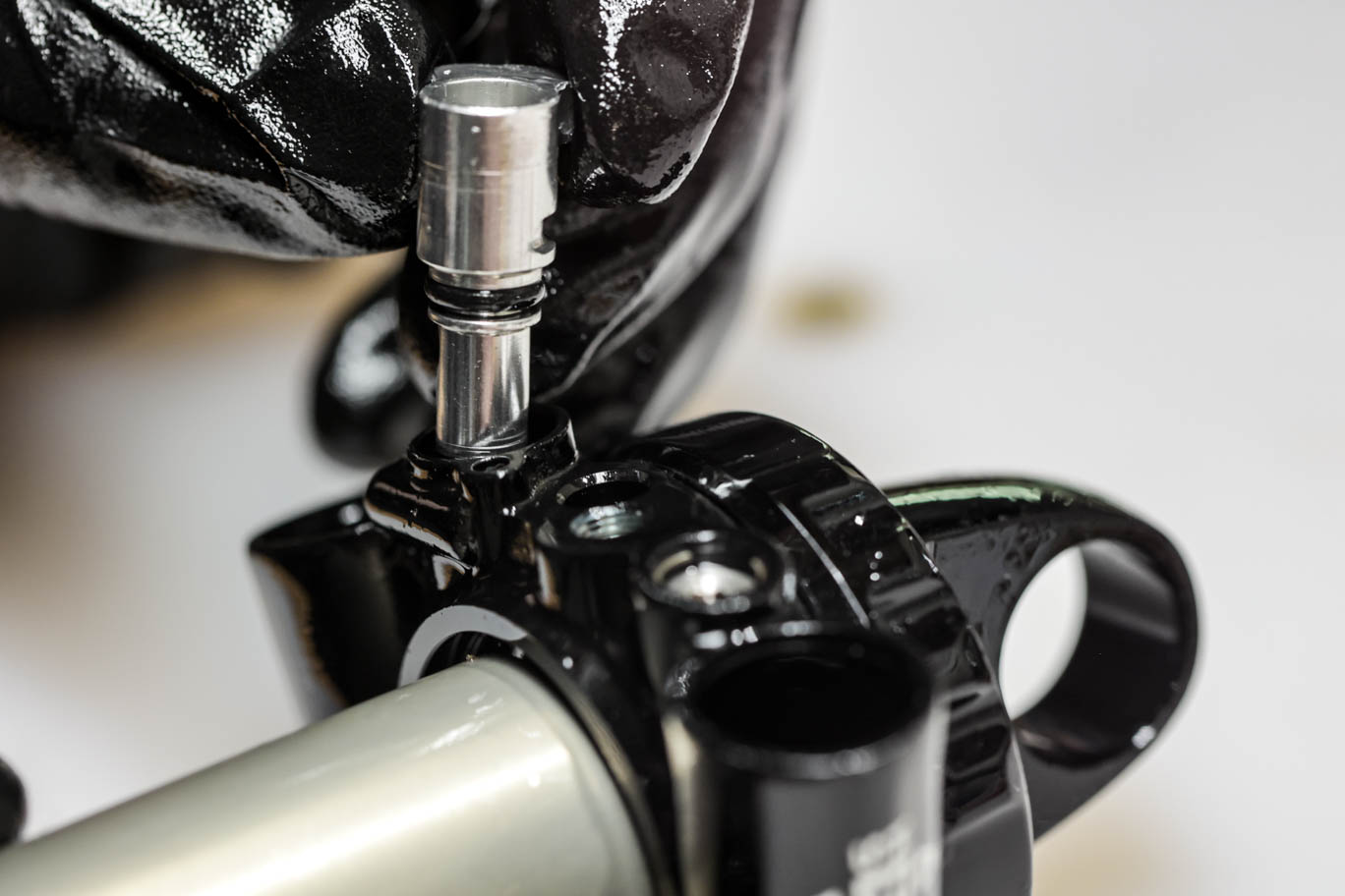
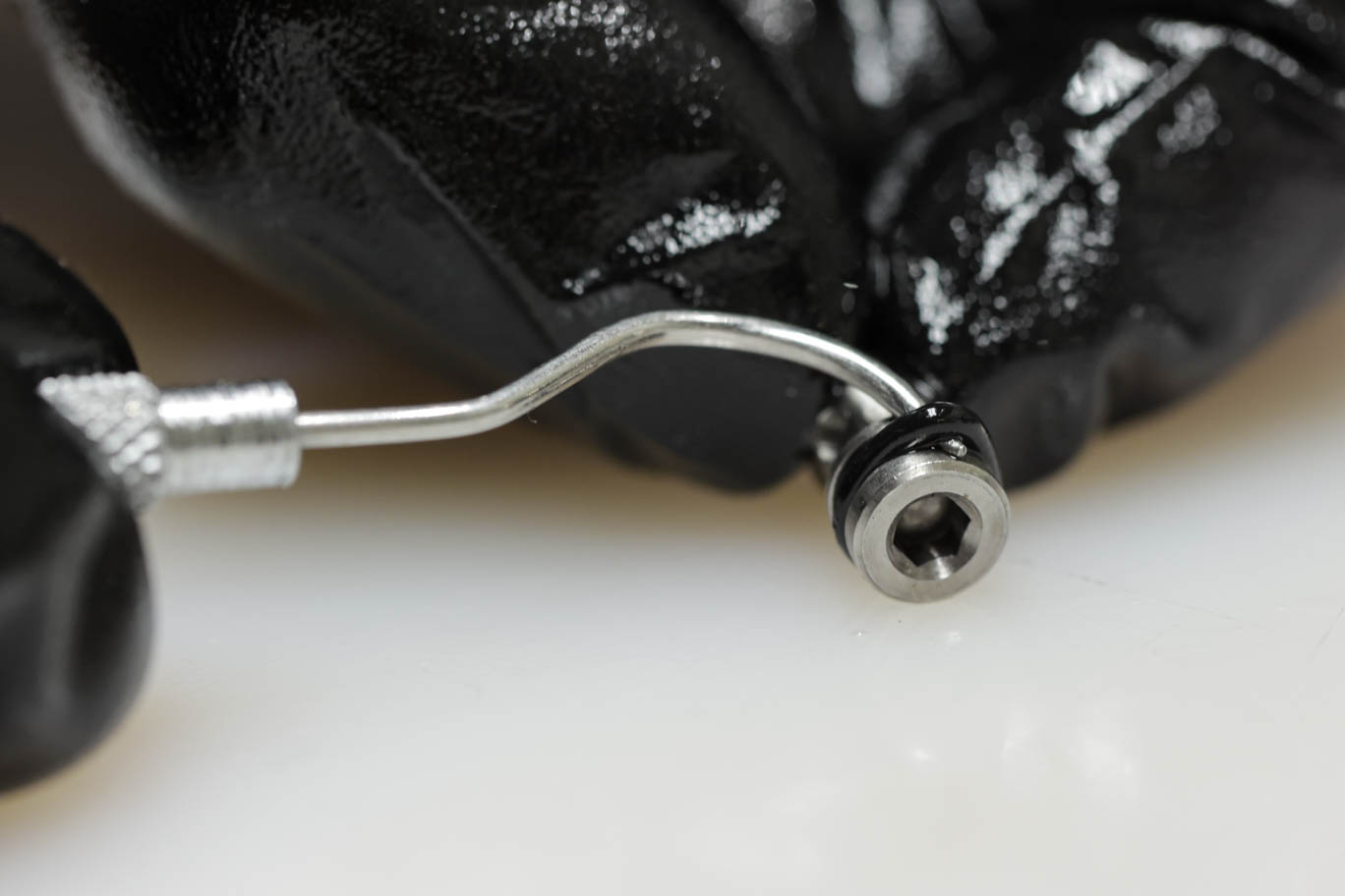
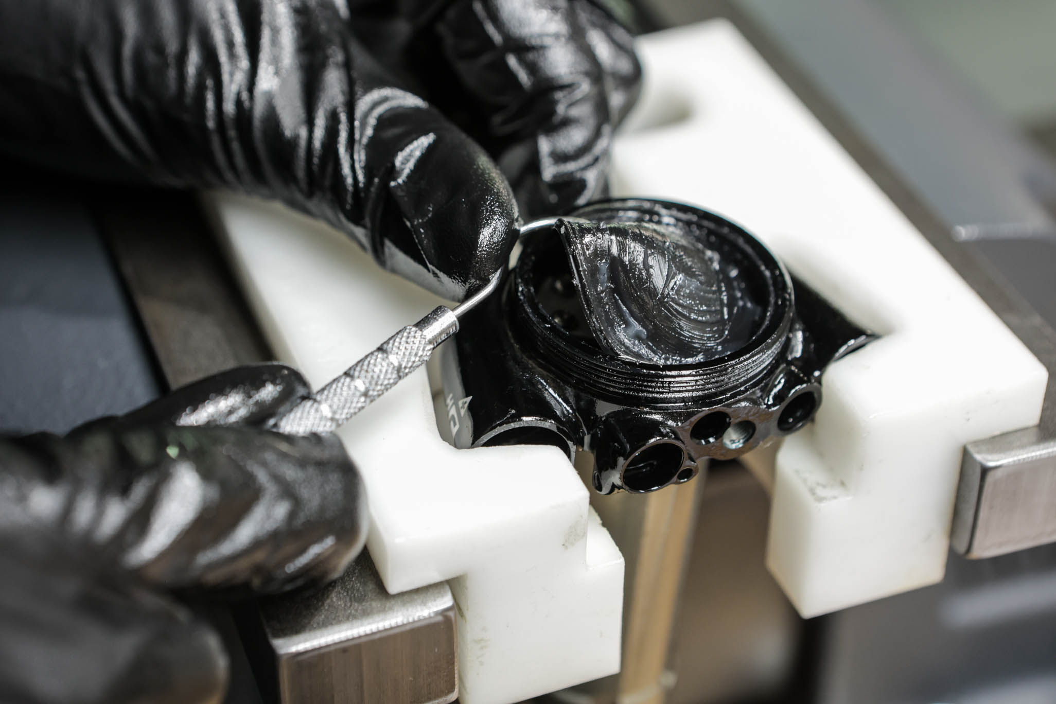
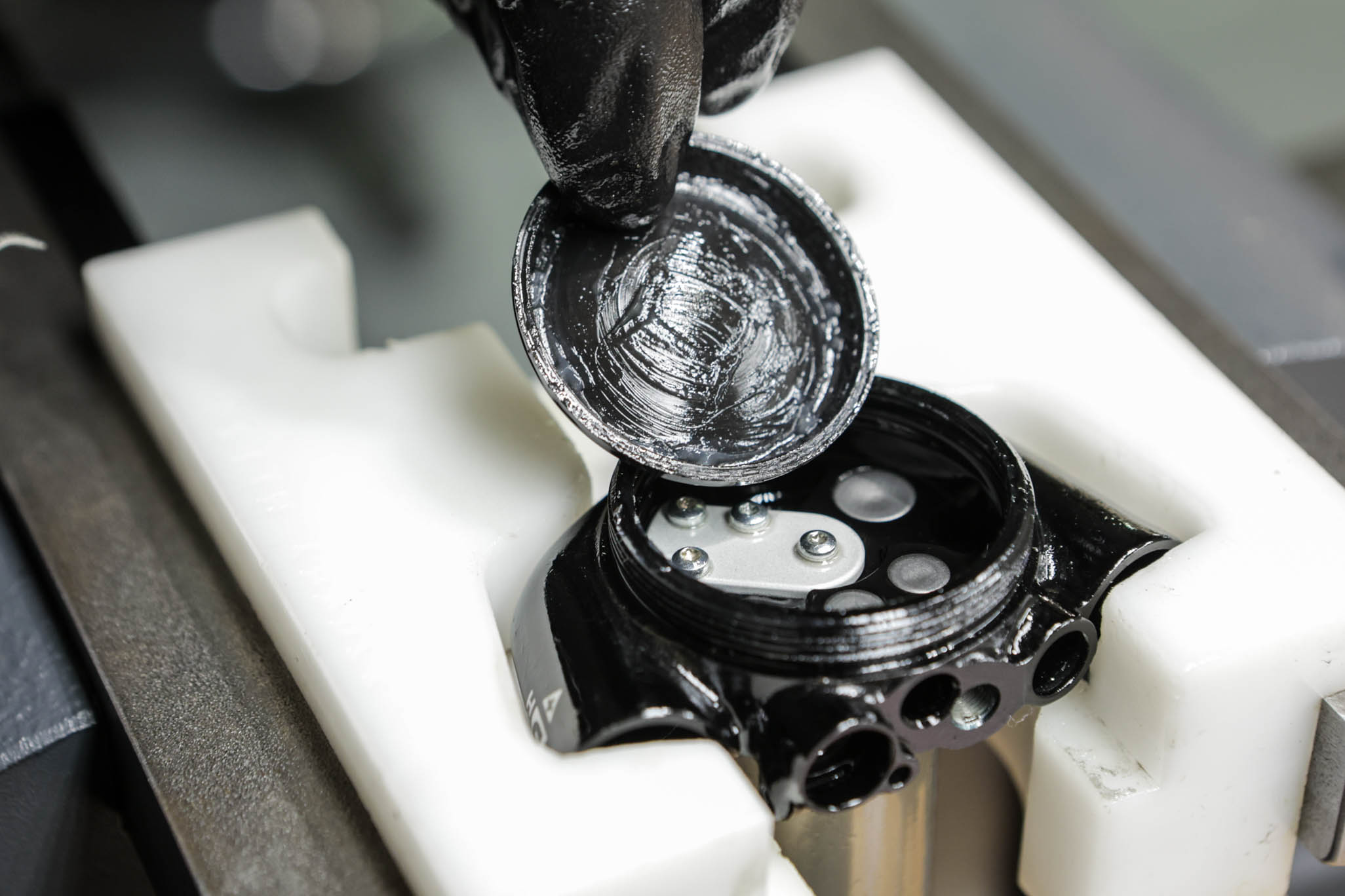
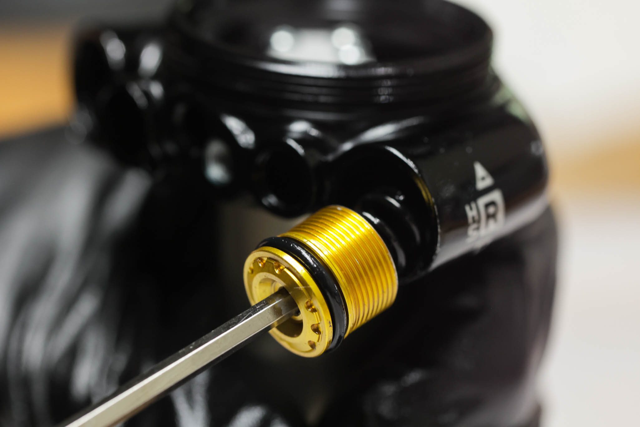
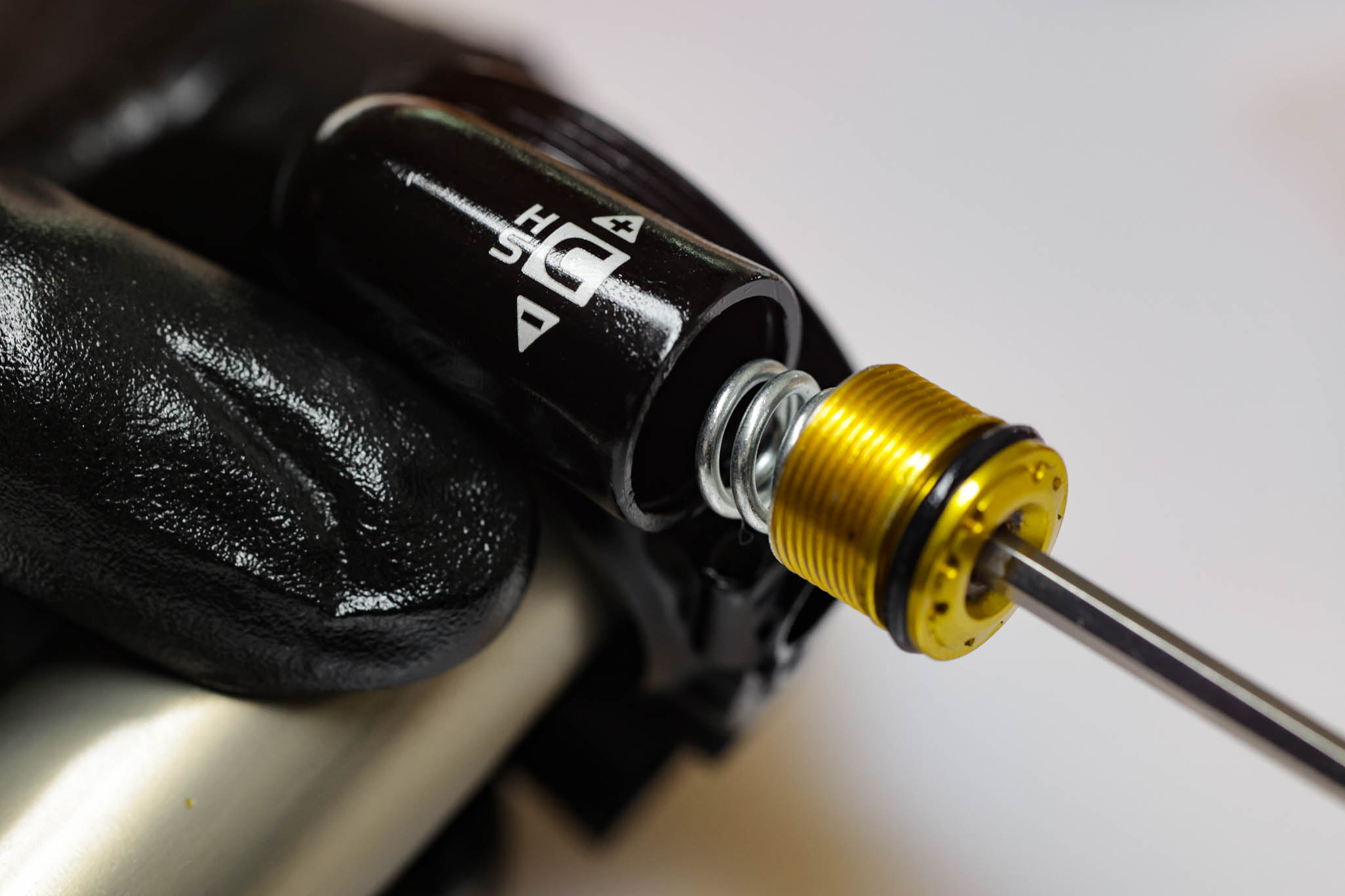
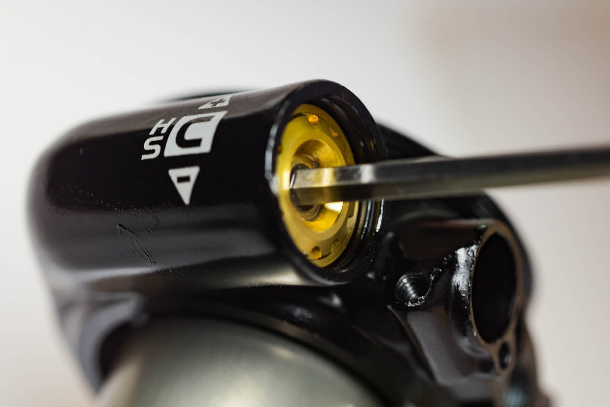
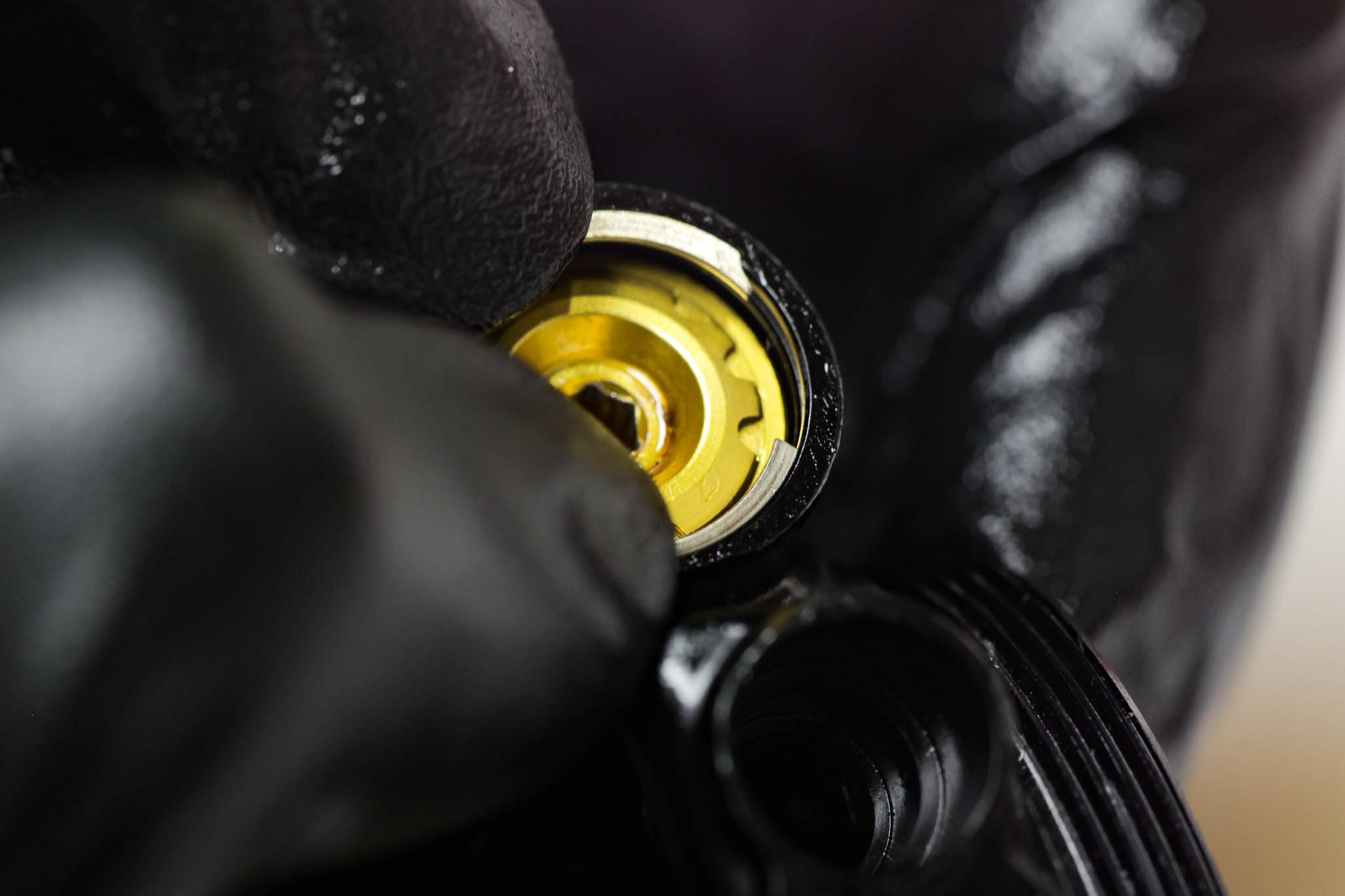
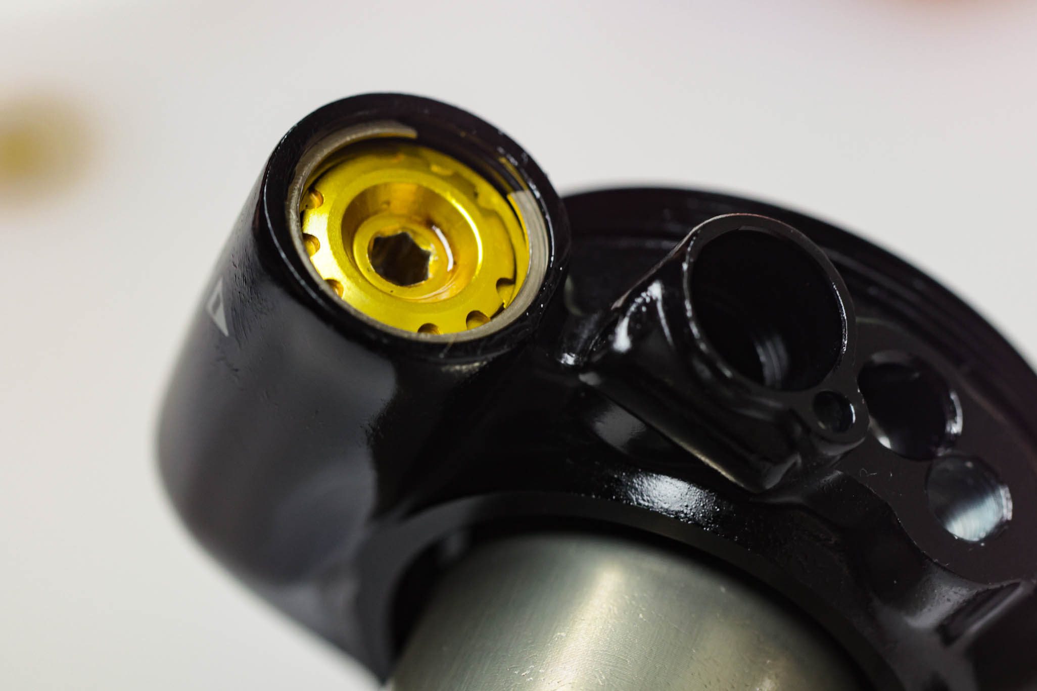
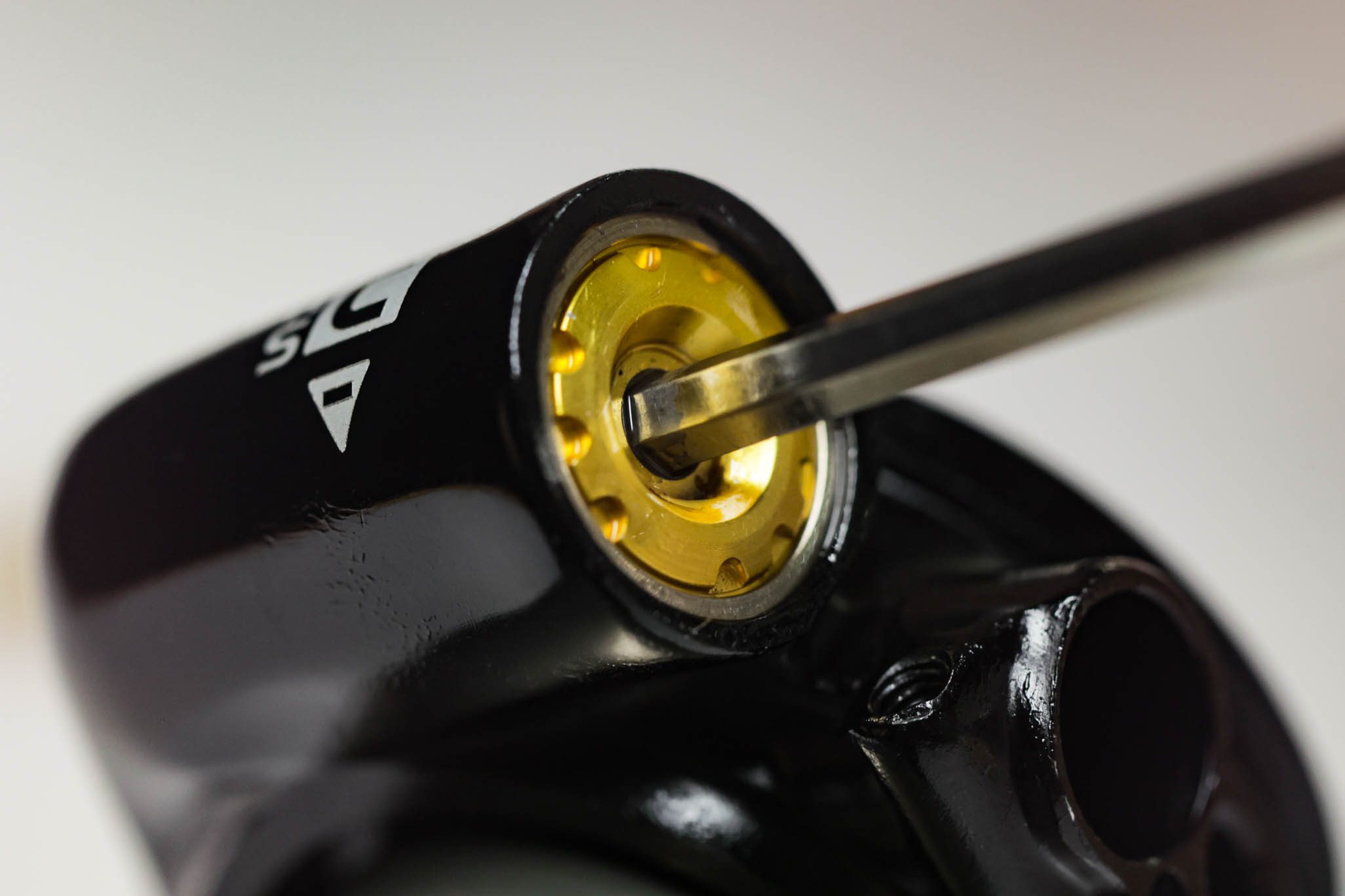
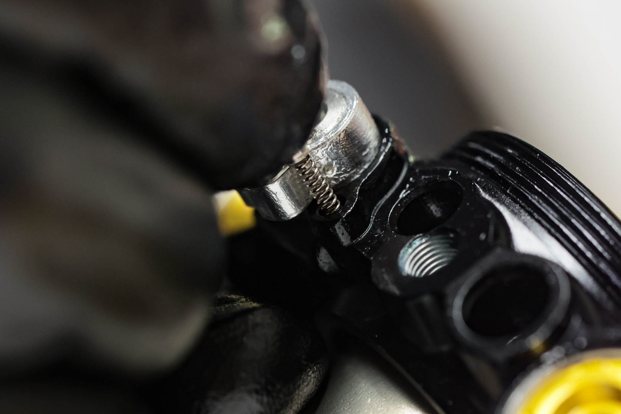
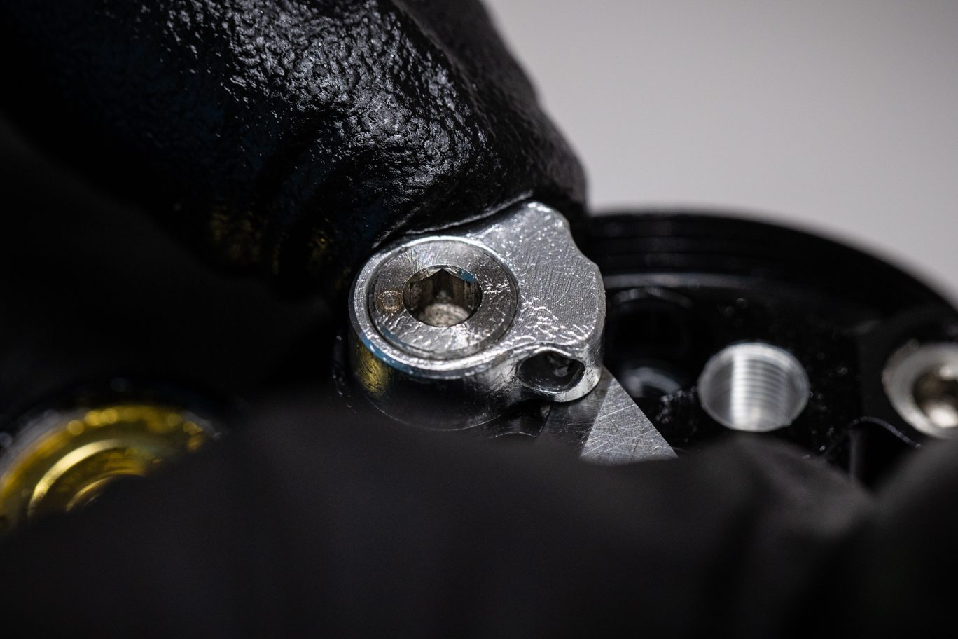
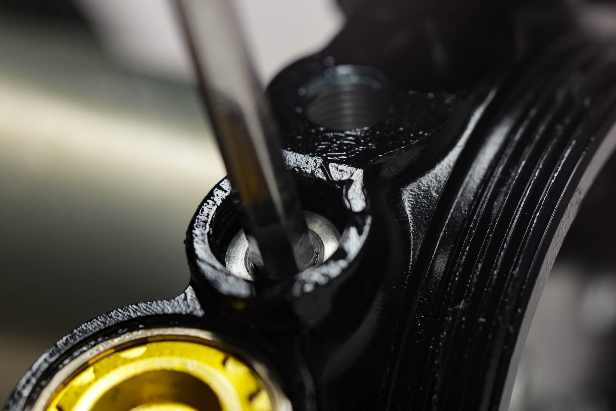
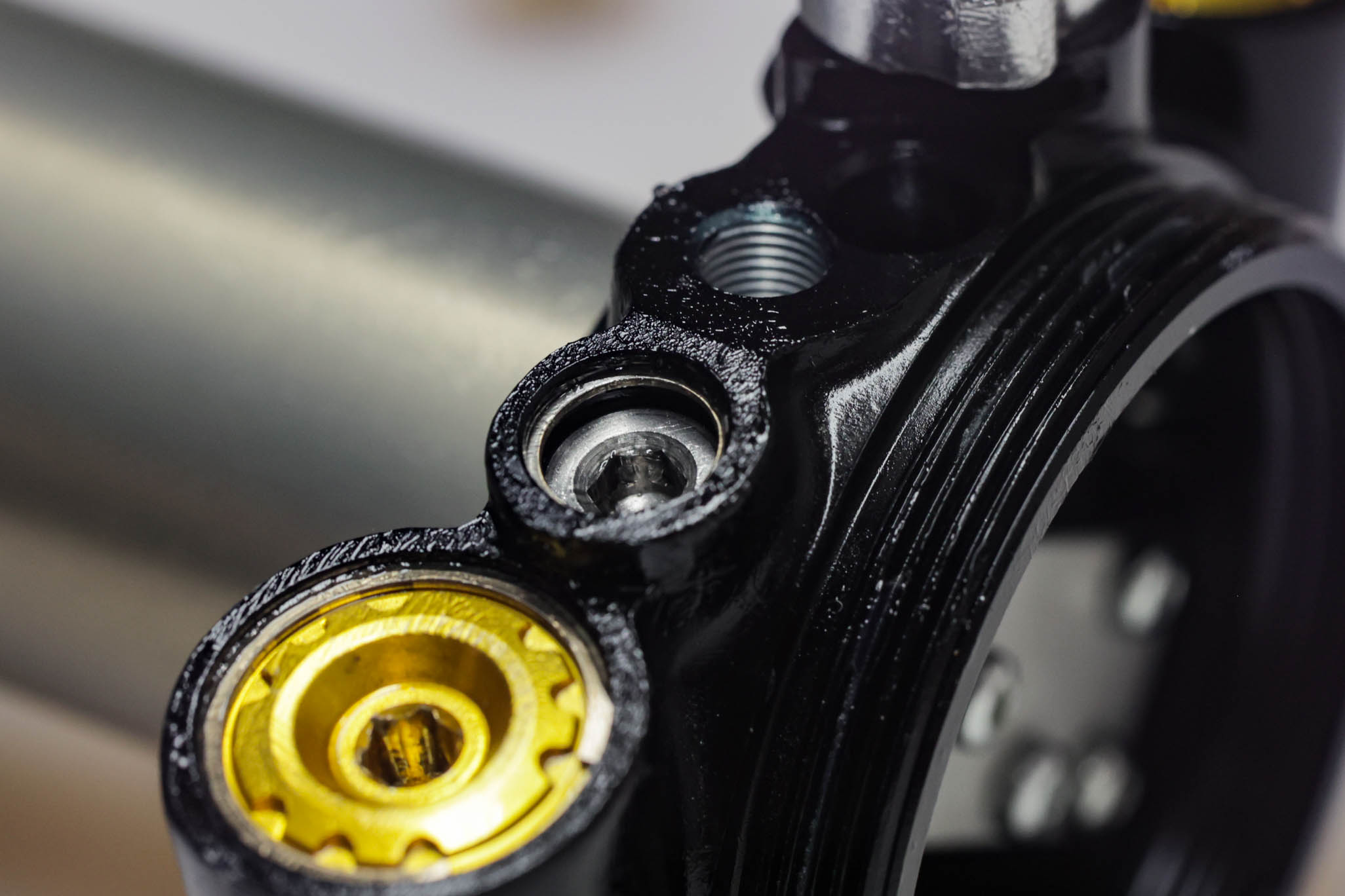
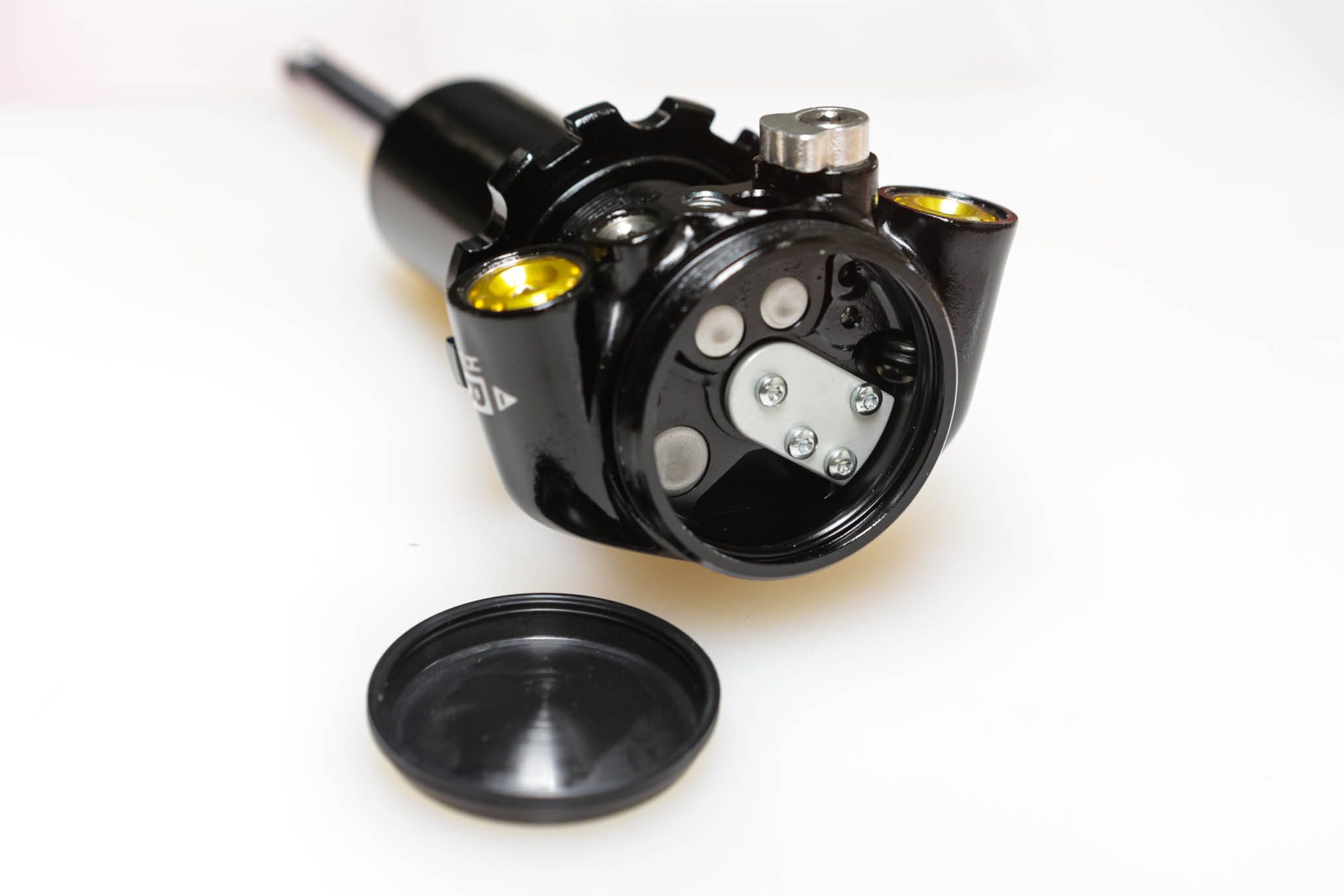
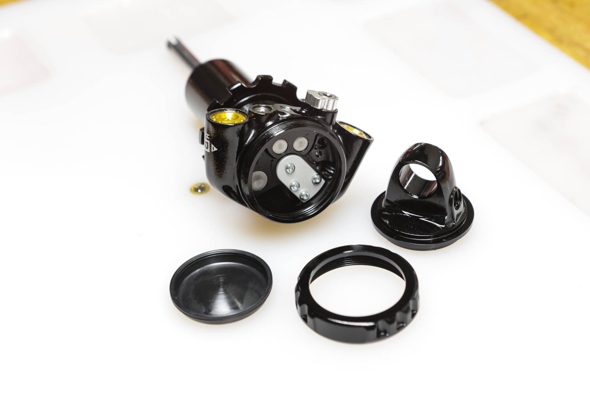
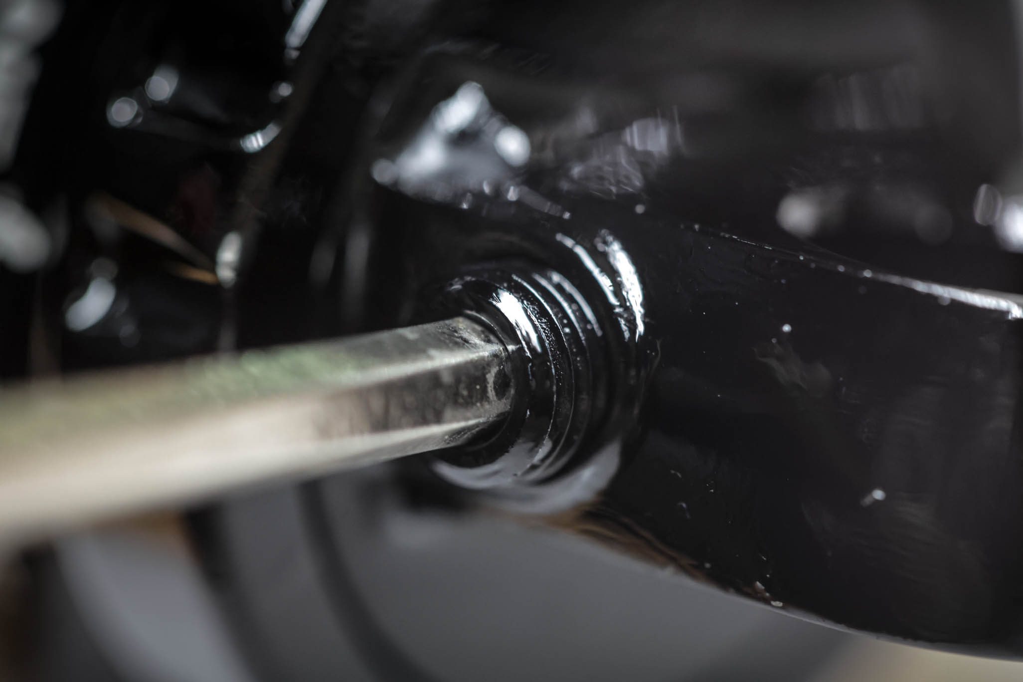
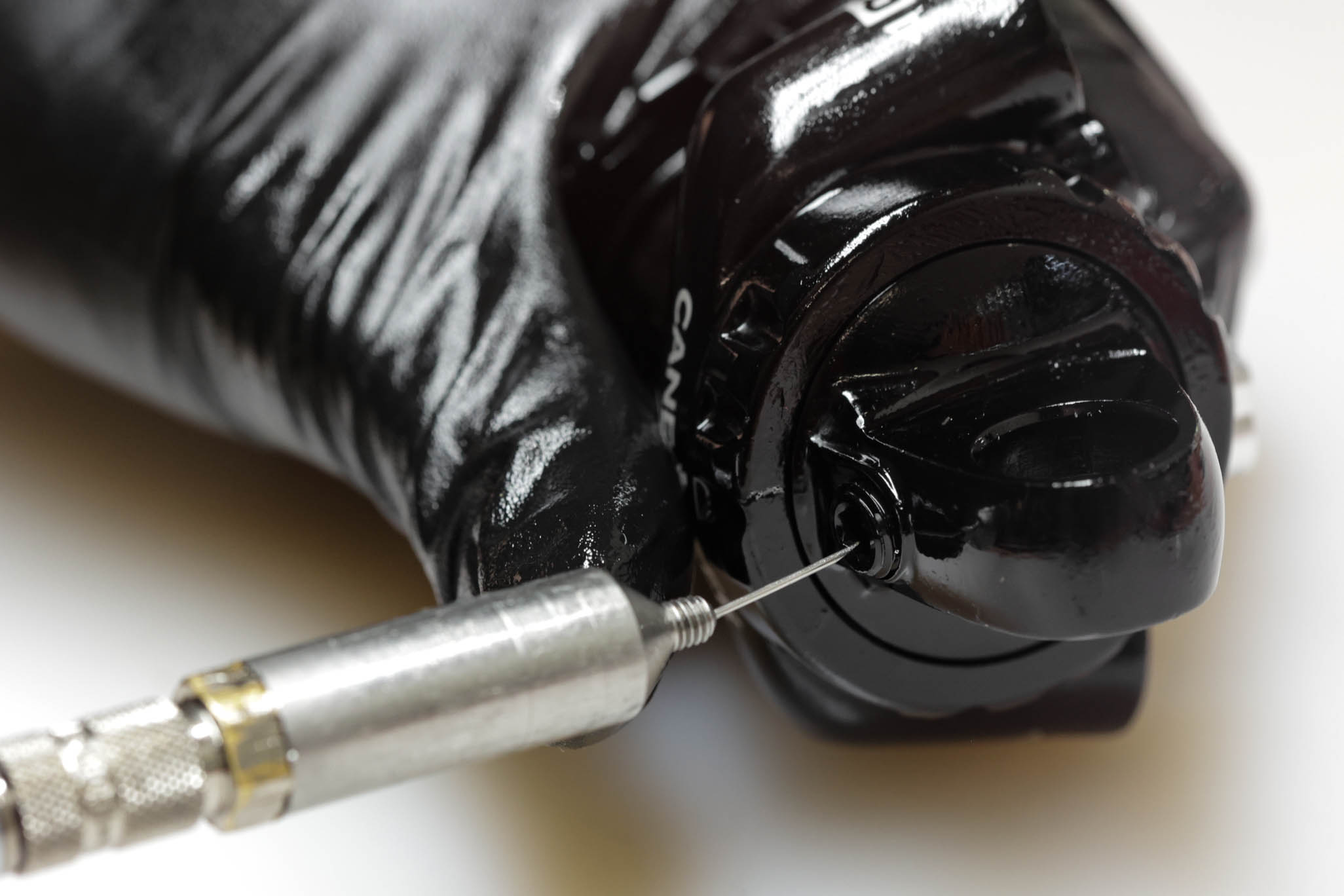
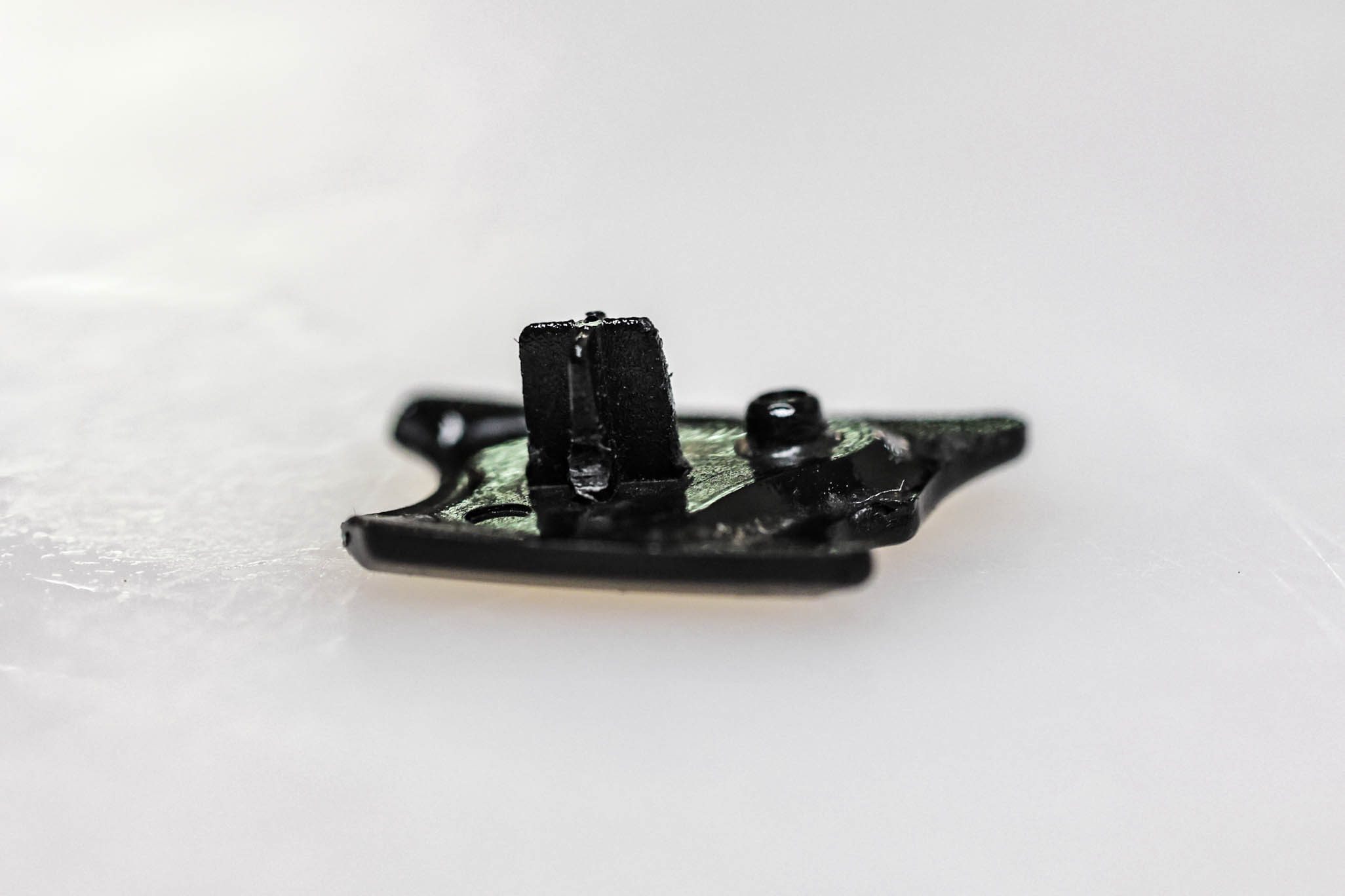
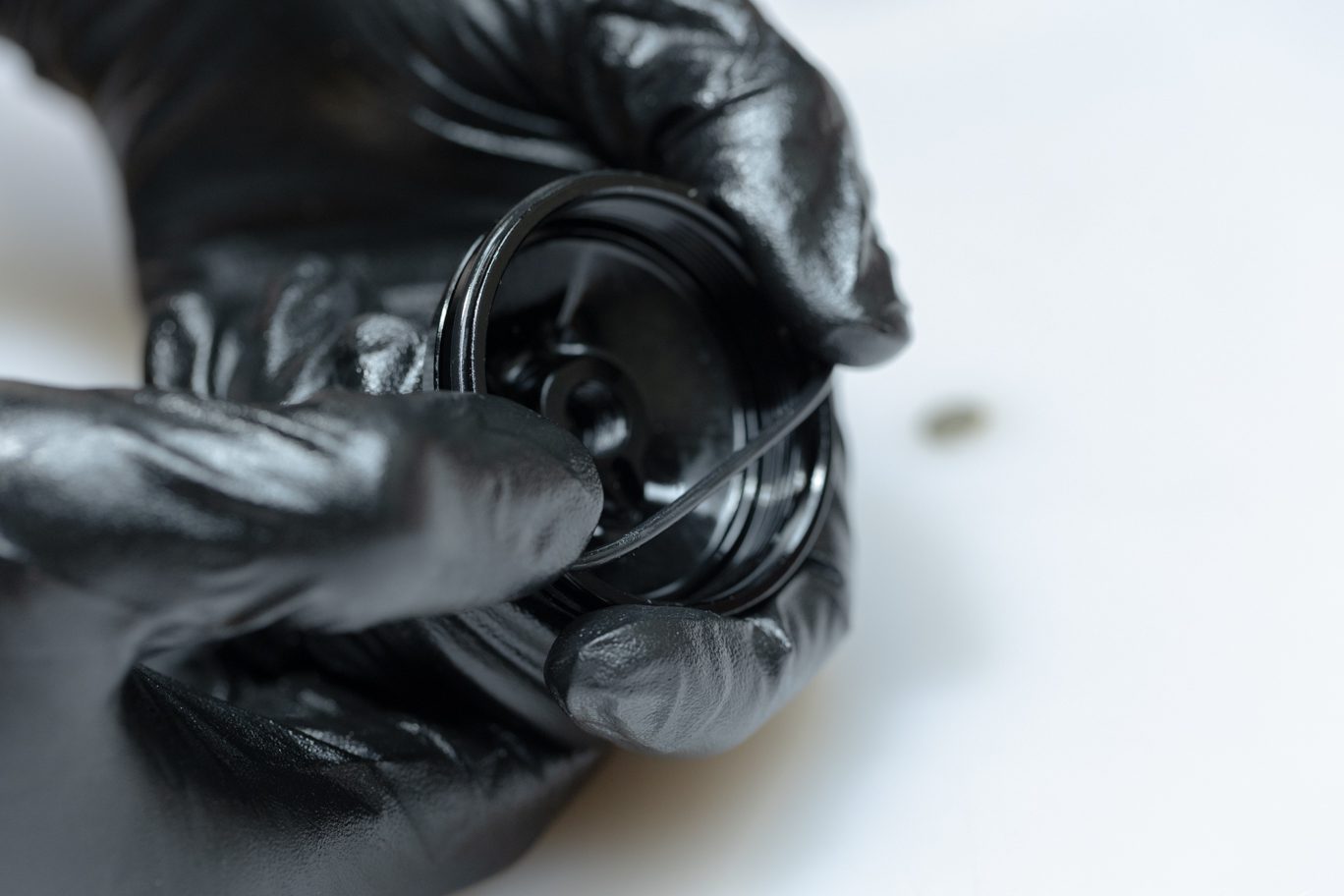
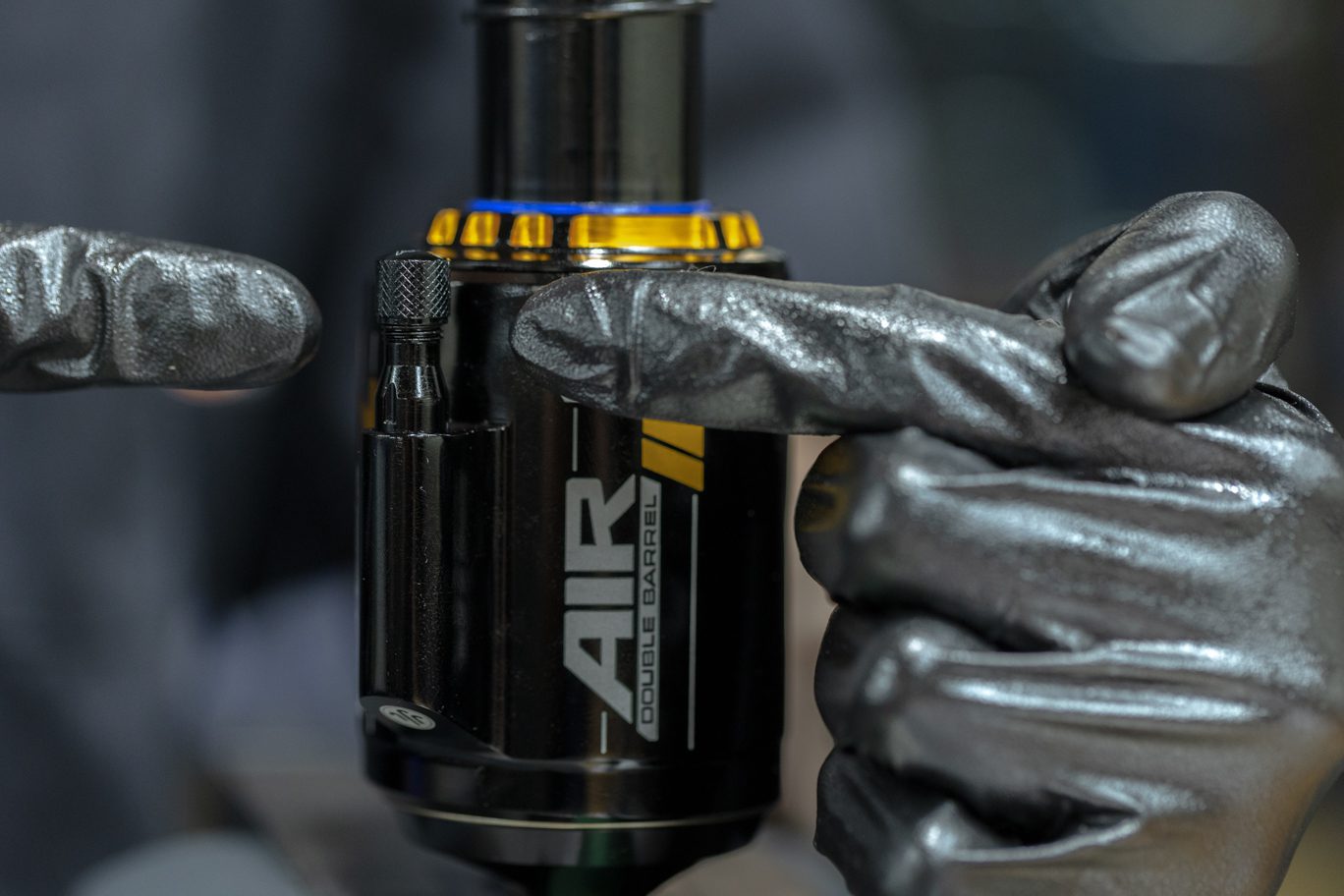
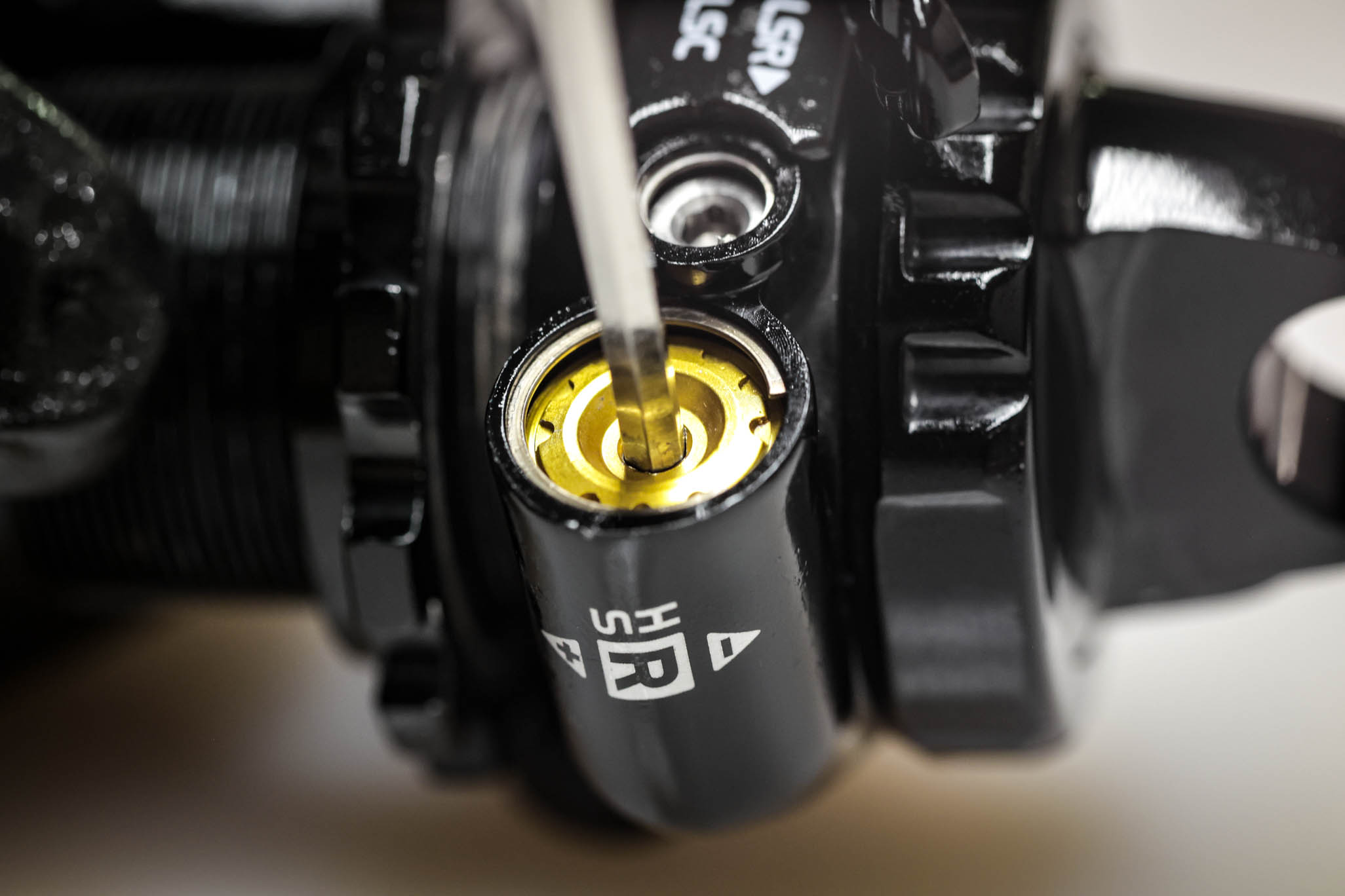
Loosen gas fill cover half a turn with 4mm Allen. Bleed gas with gas fill needle. Remove gas fill cover completely. Use pick to pry out gas fill plug.
Always use extreme caution when using a pick in this step or others to avoid scratching metal parts. Failure to do this can create scratches in the o-ring glands which cause leak paths for oil or gas.
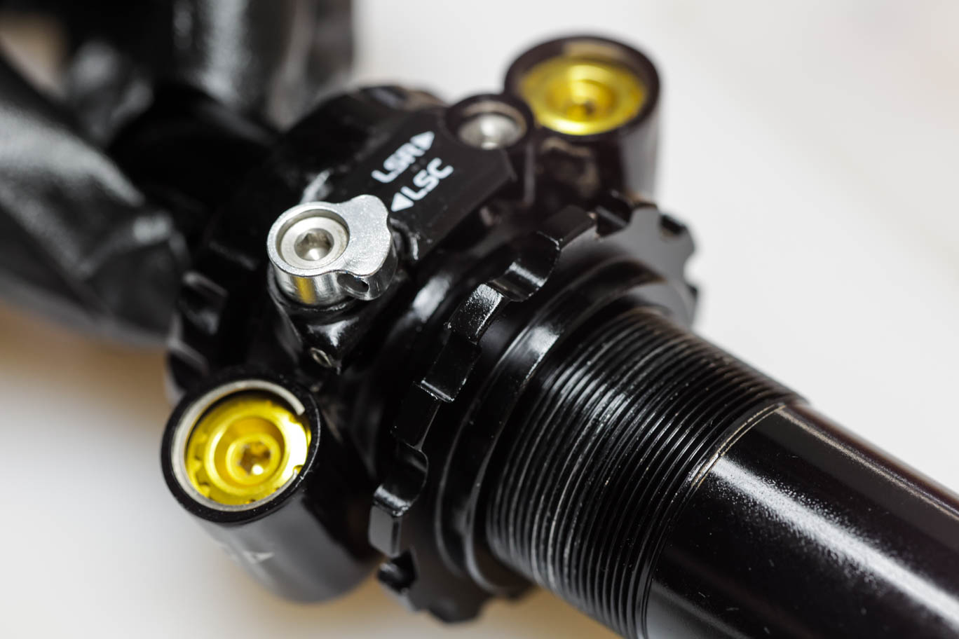
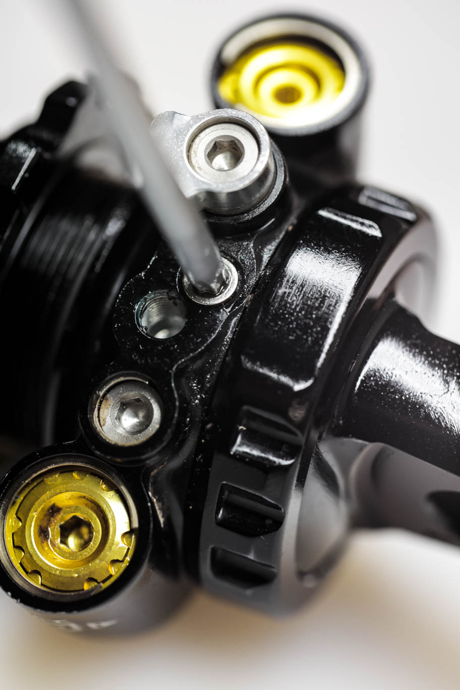
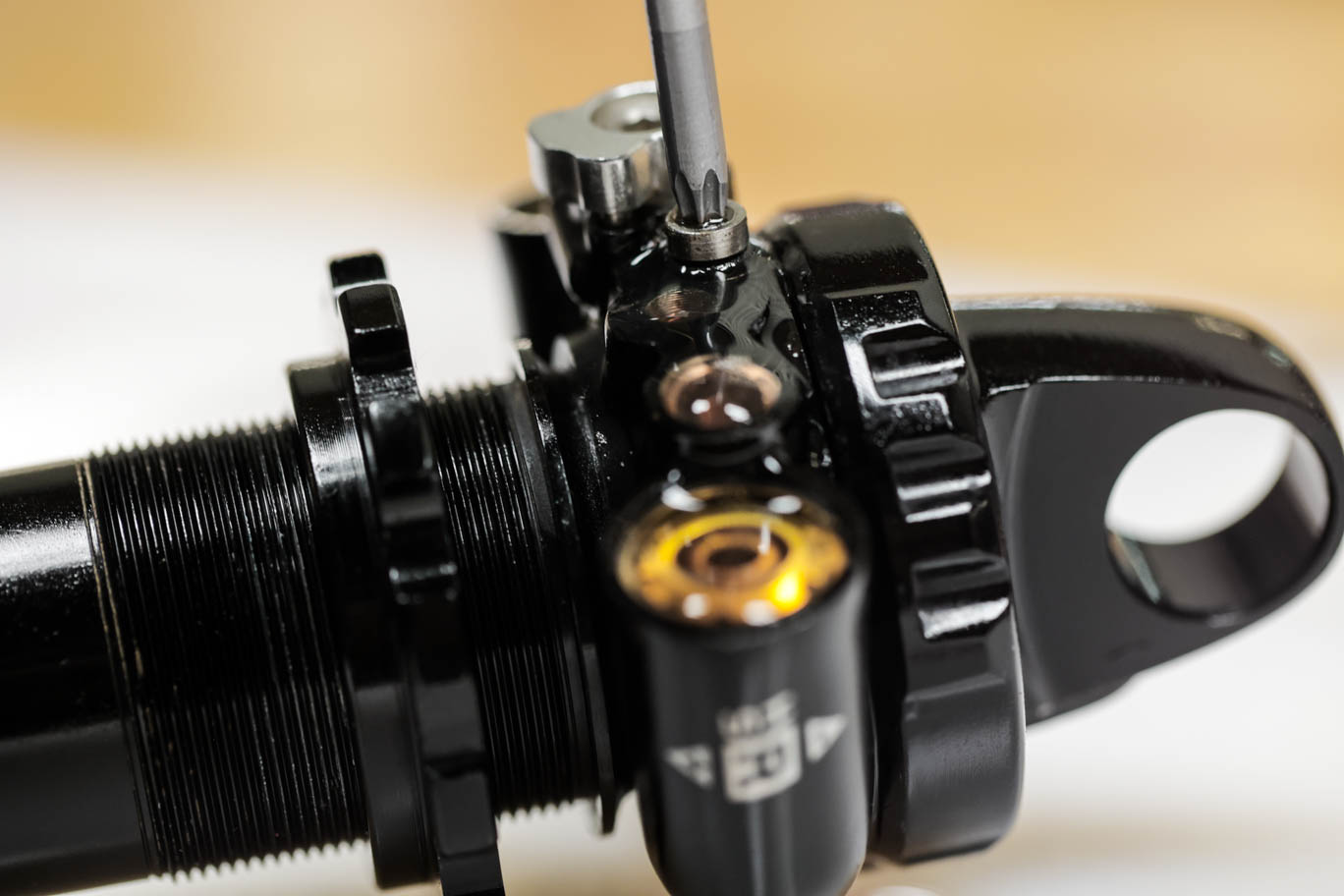
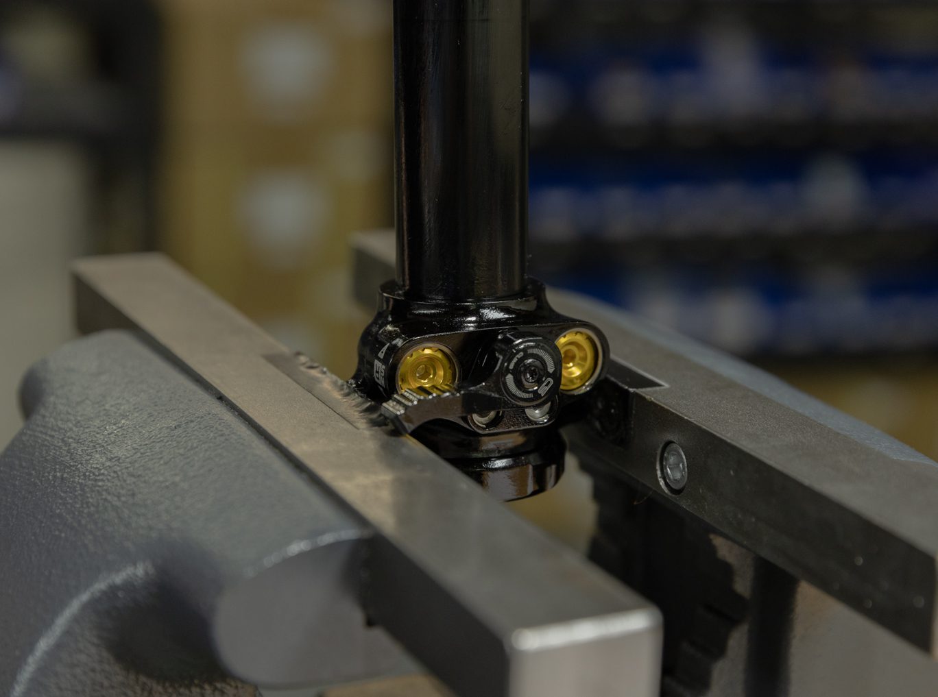
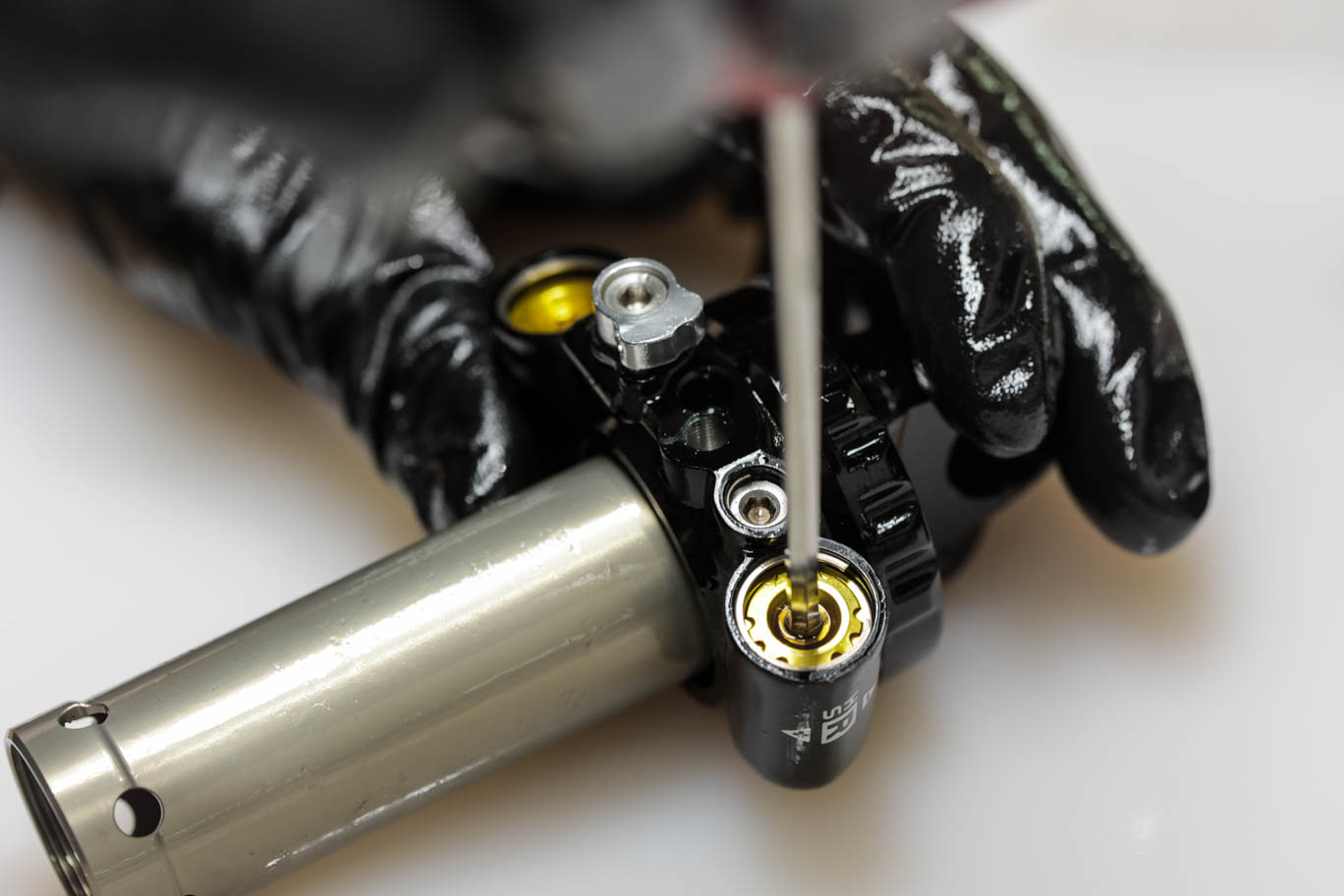
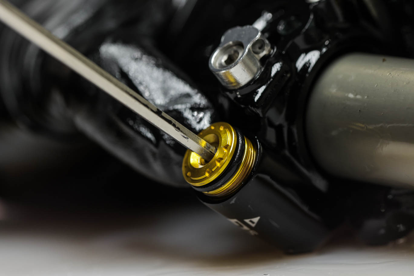
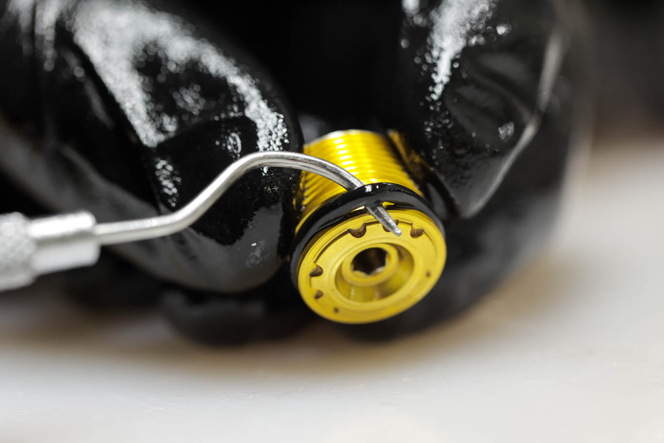
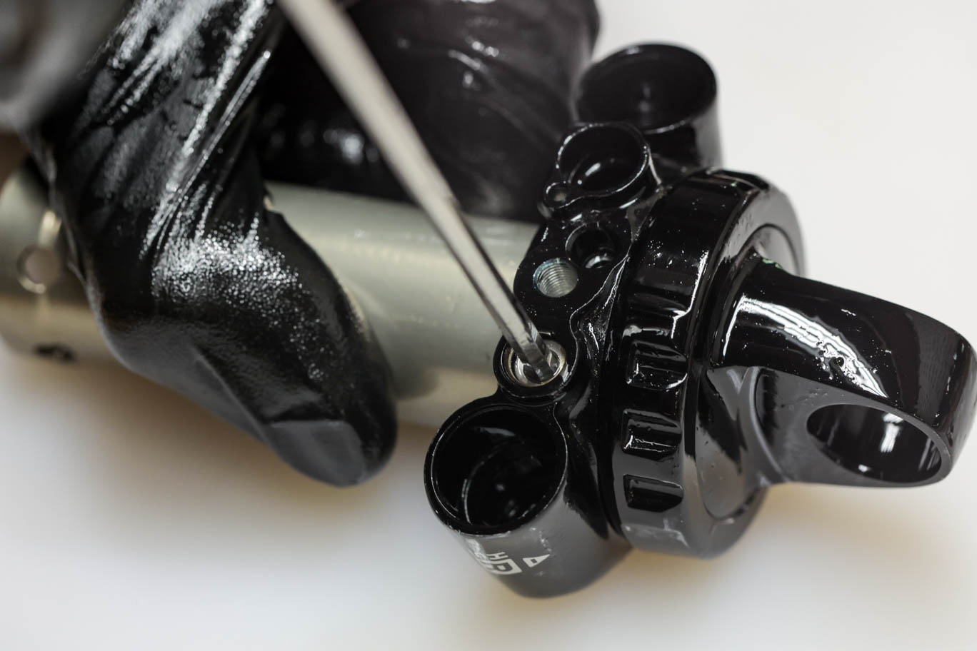
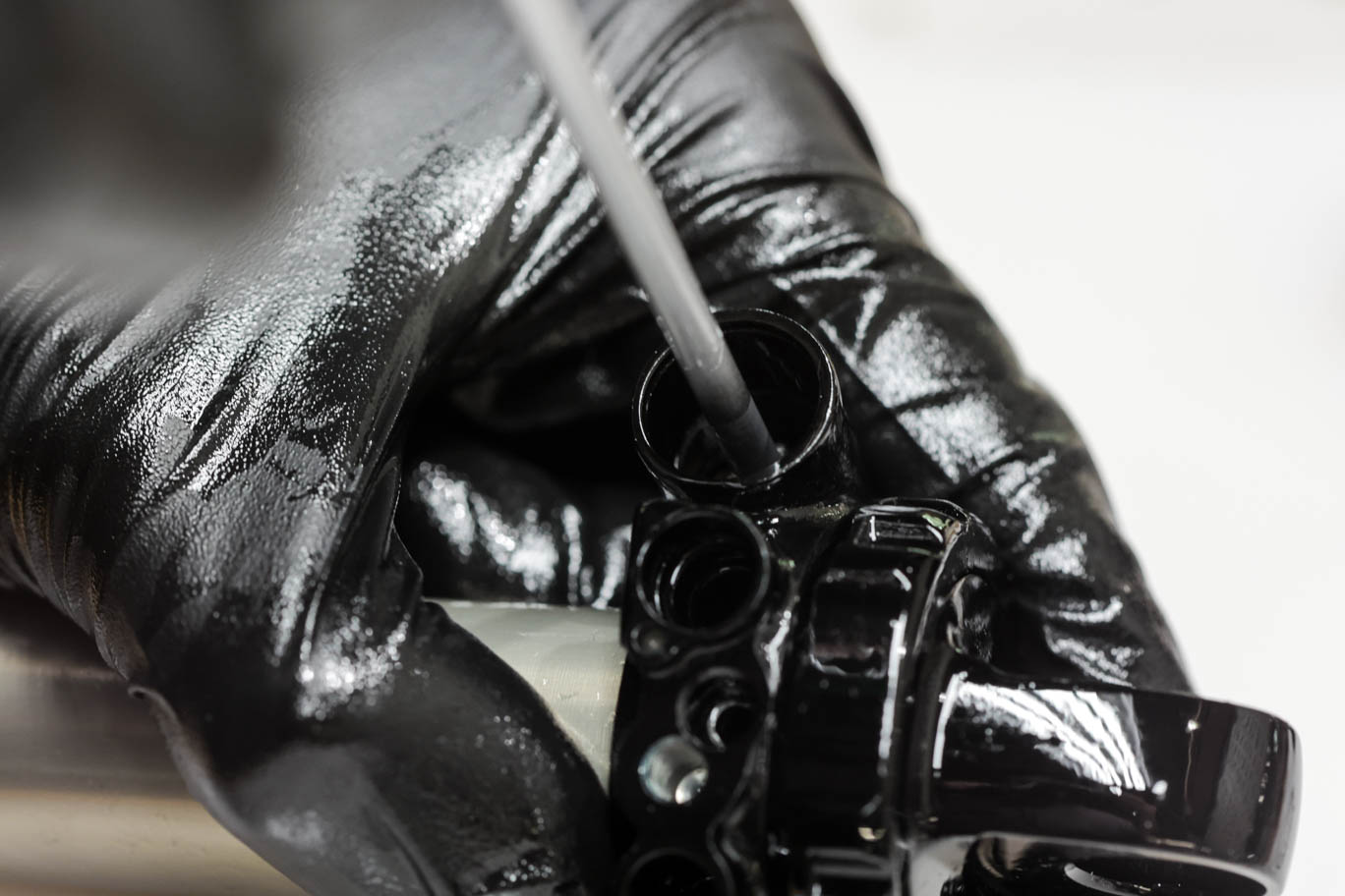
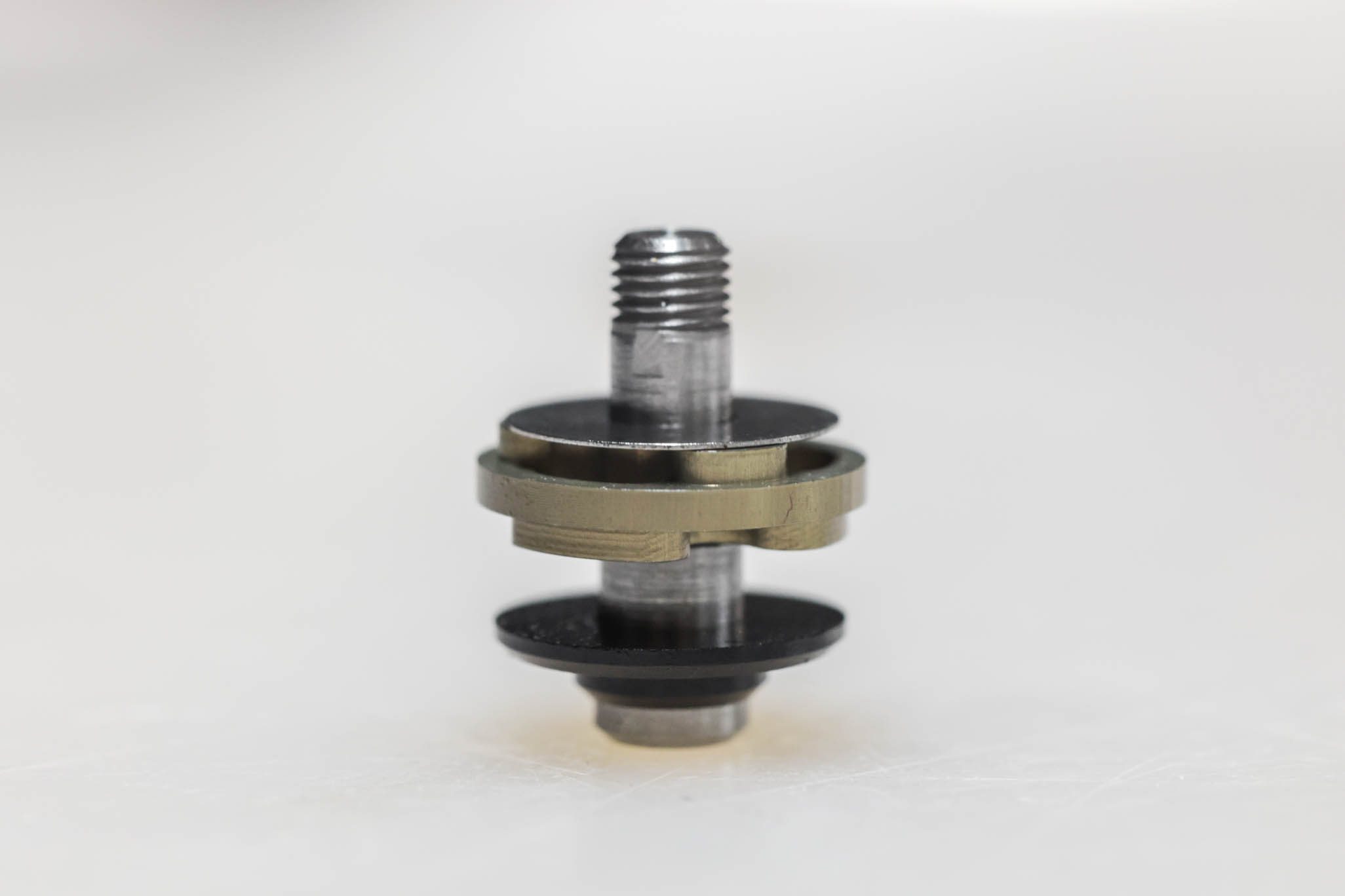
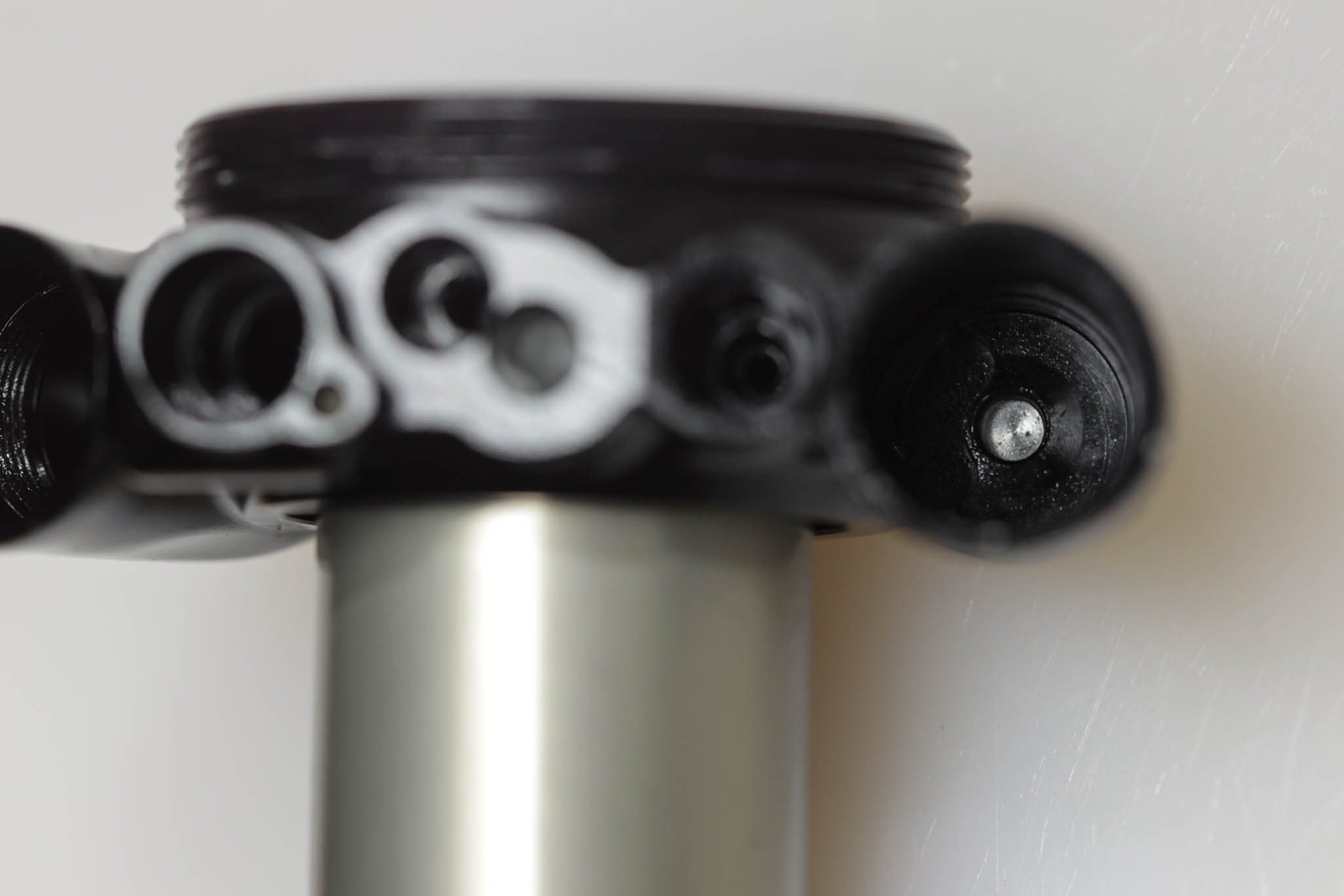
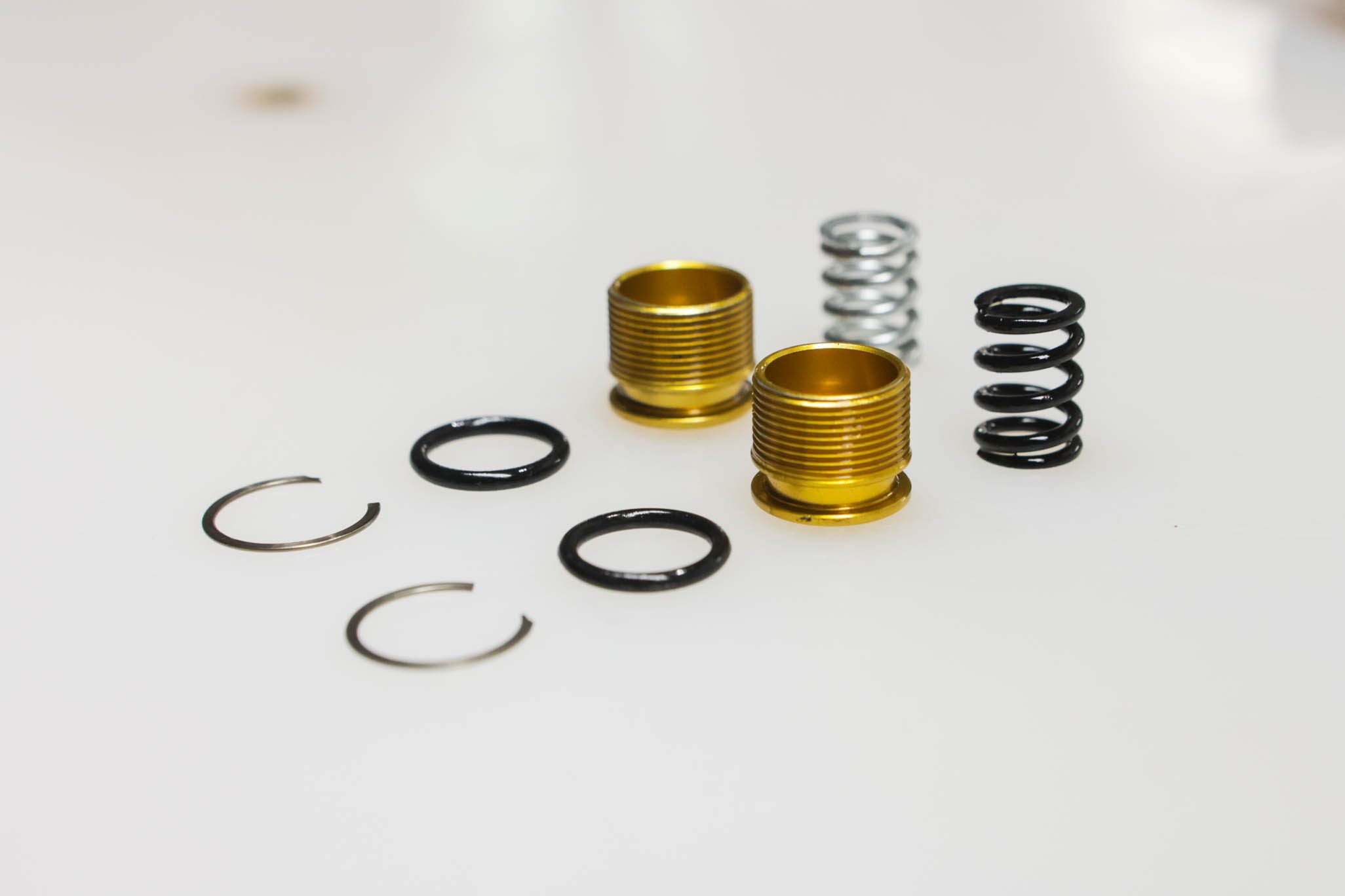
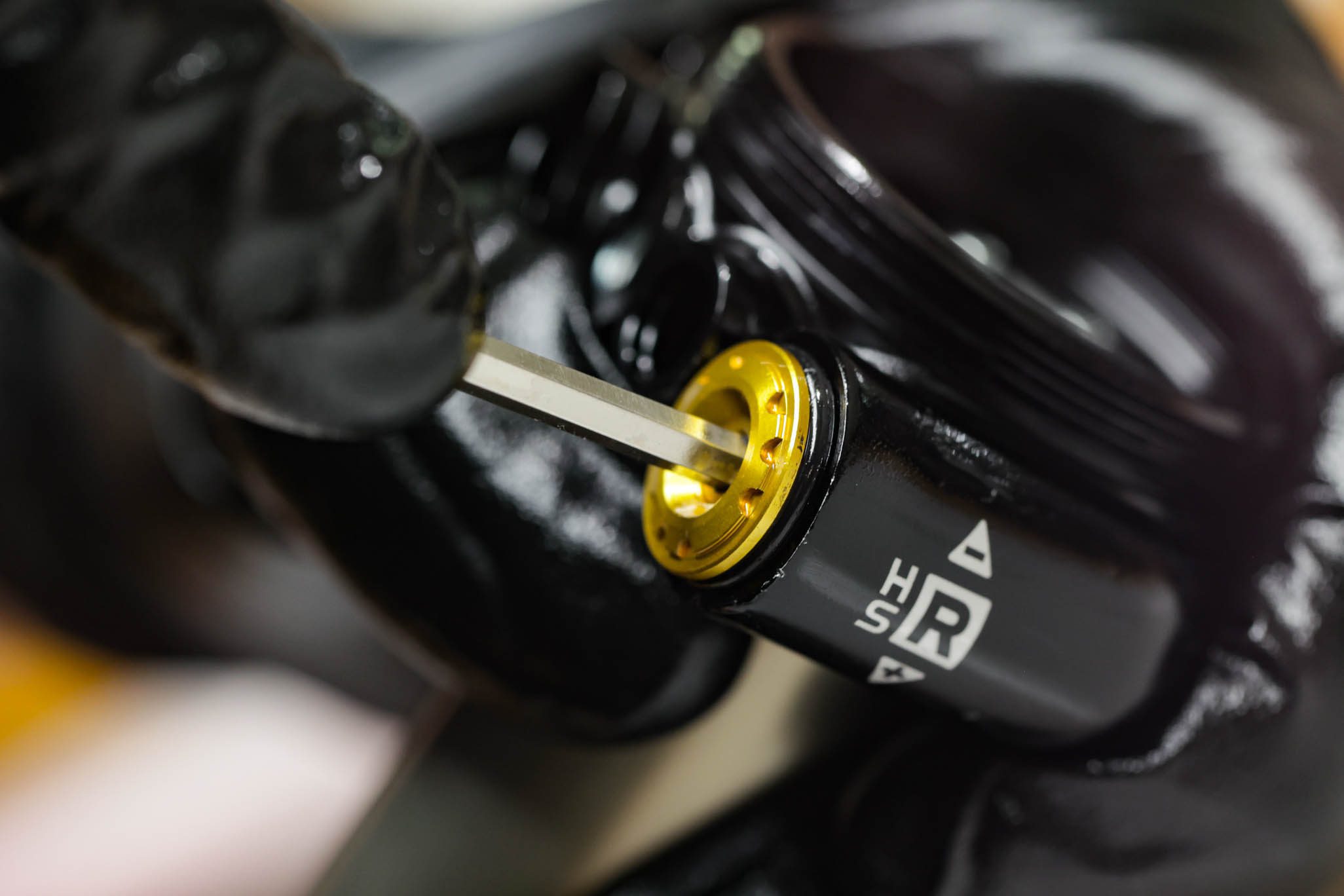
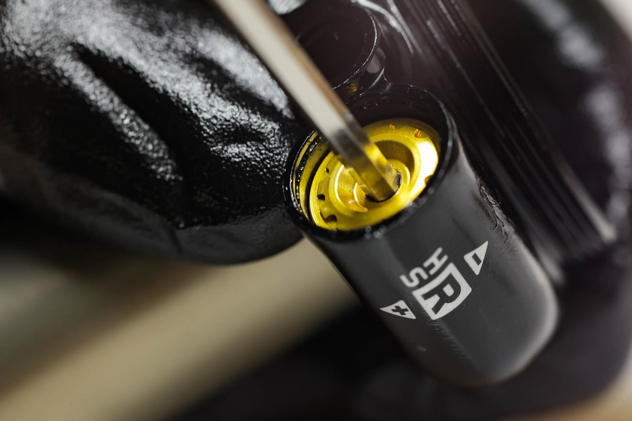
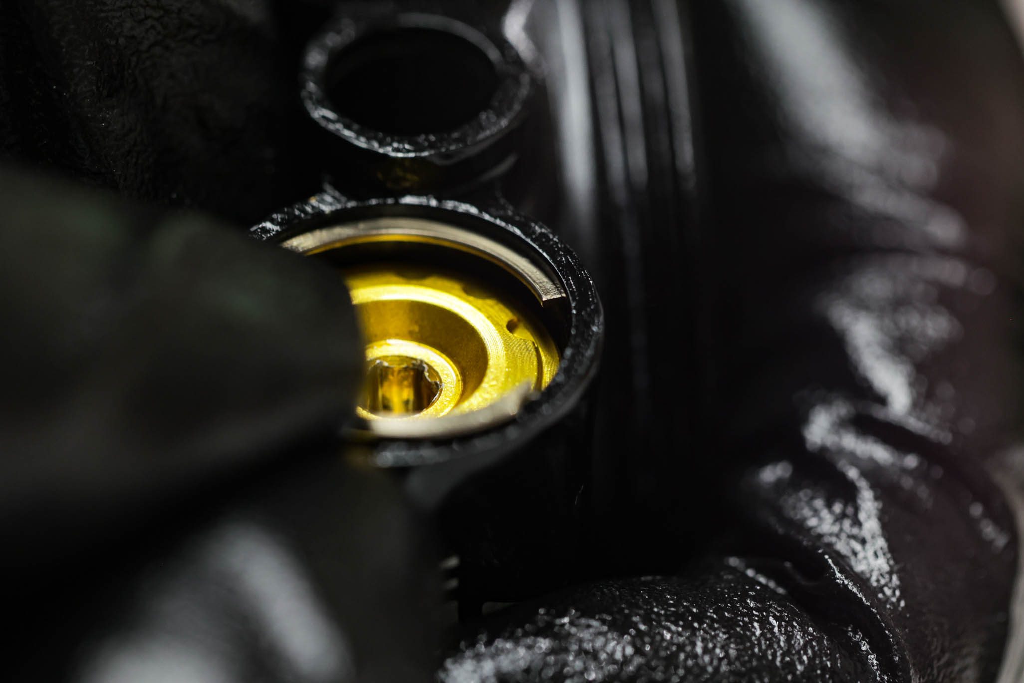
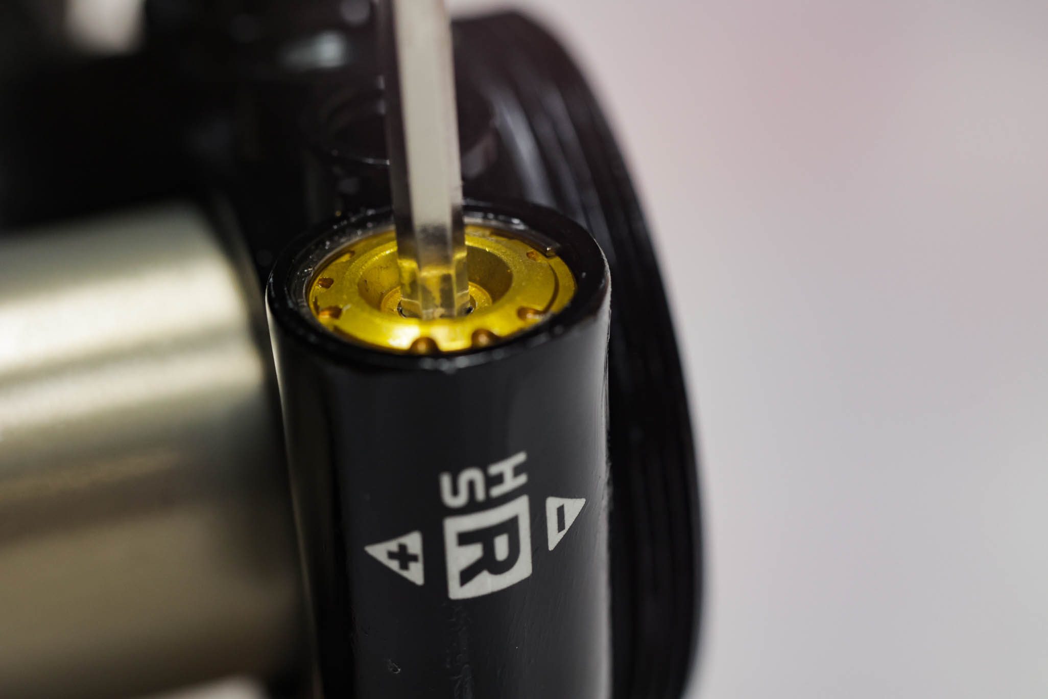
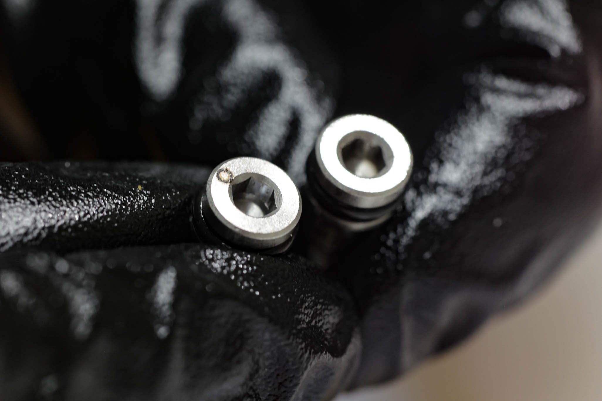
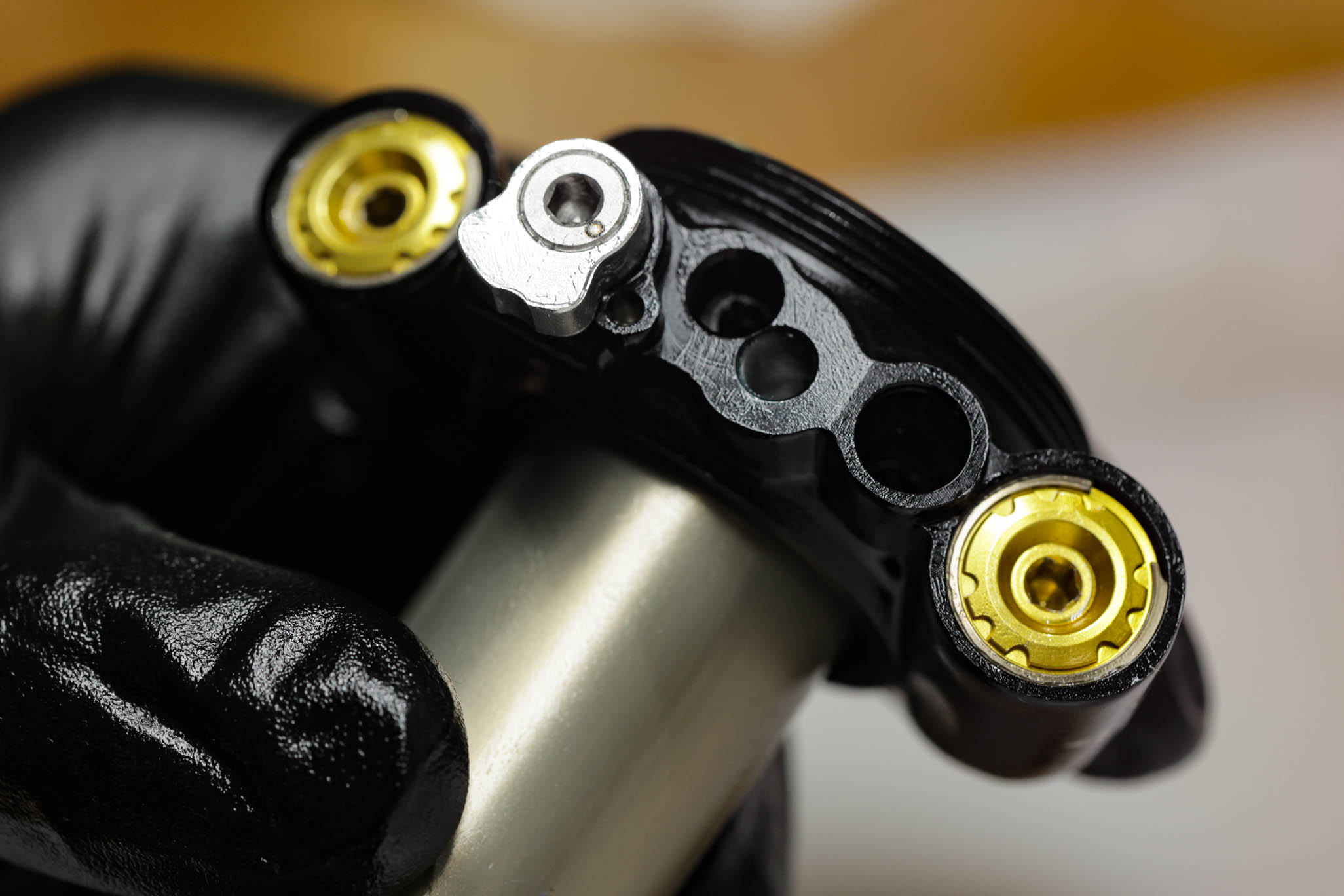
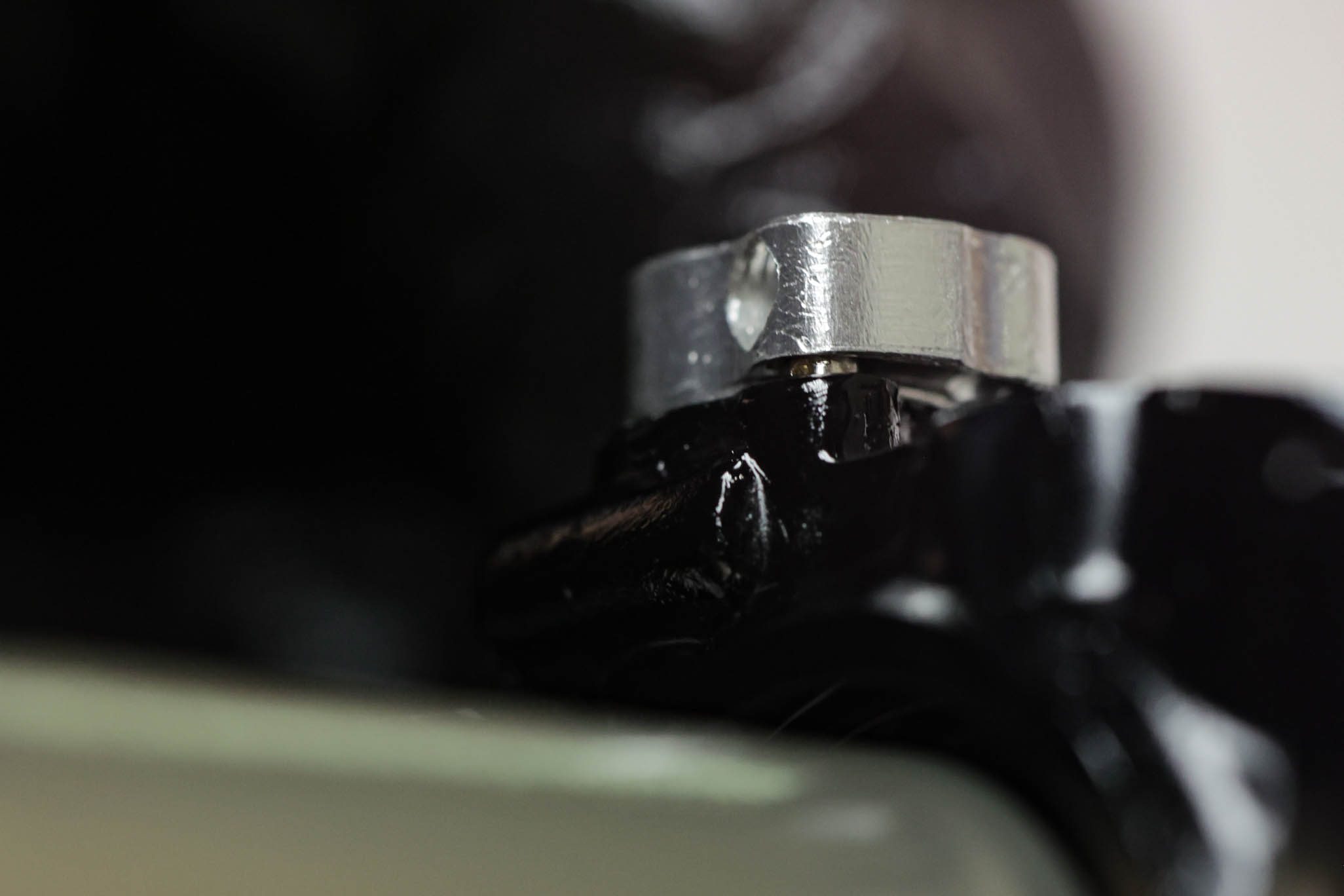
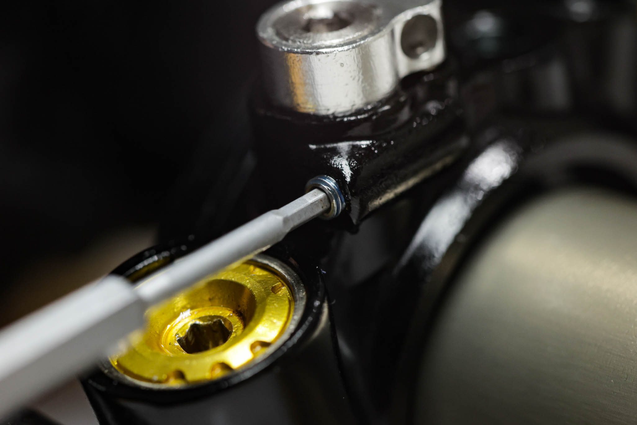
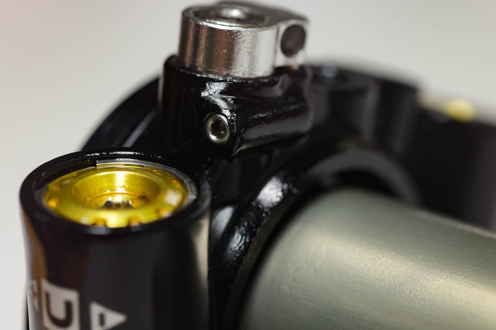
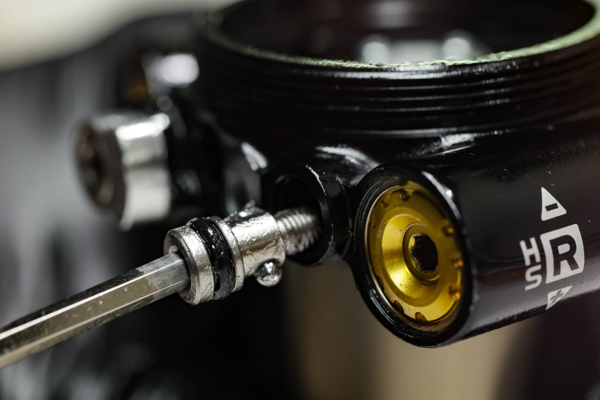
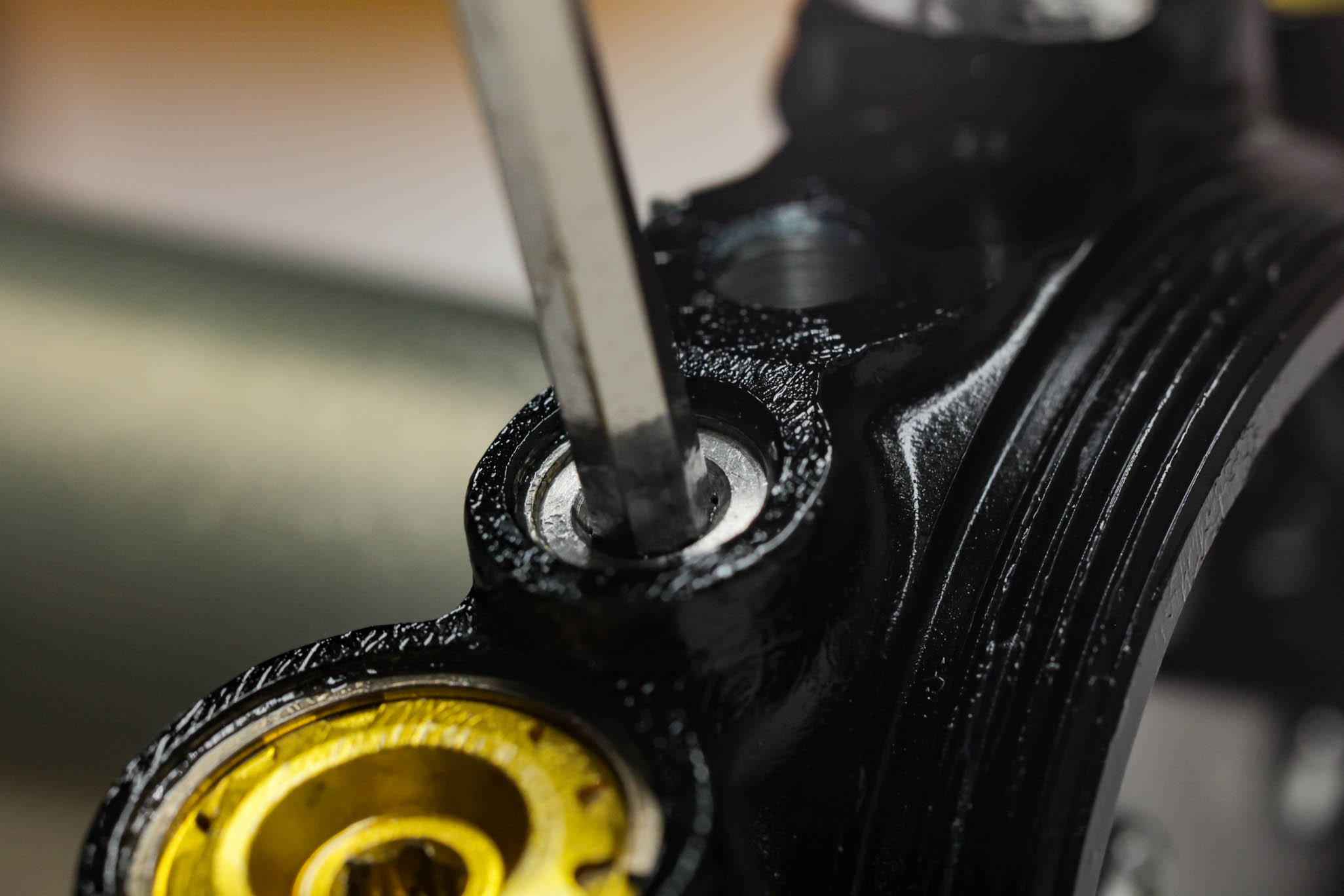
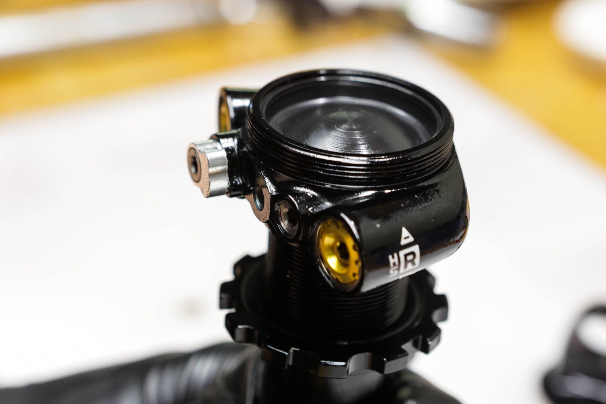
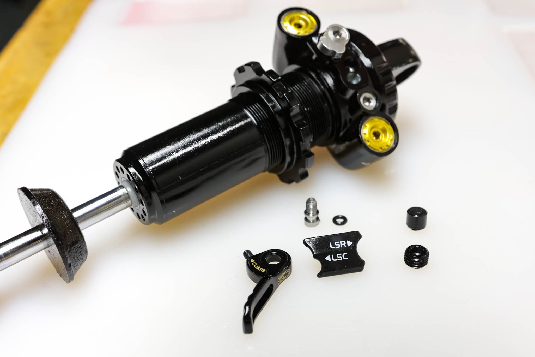
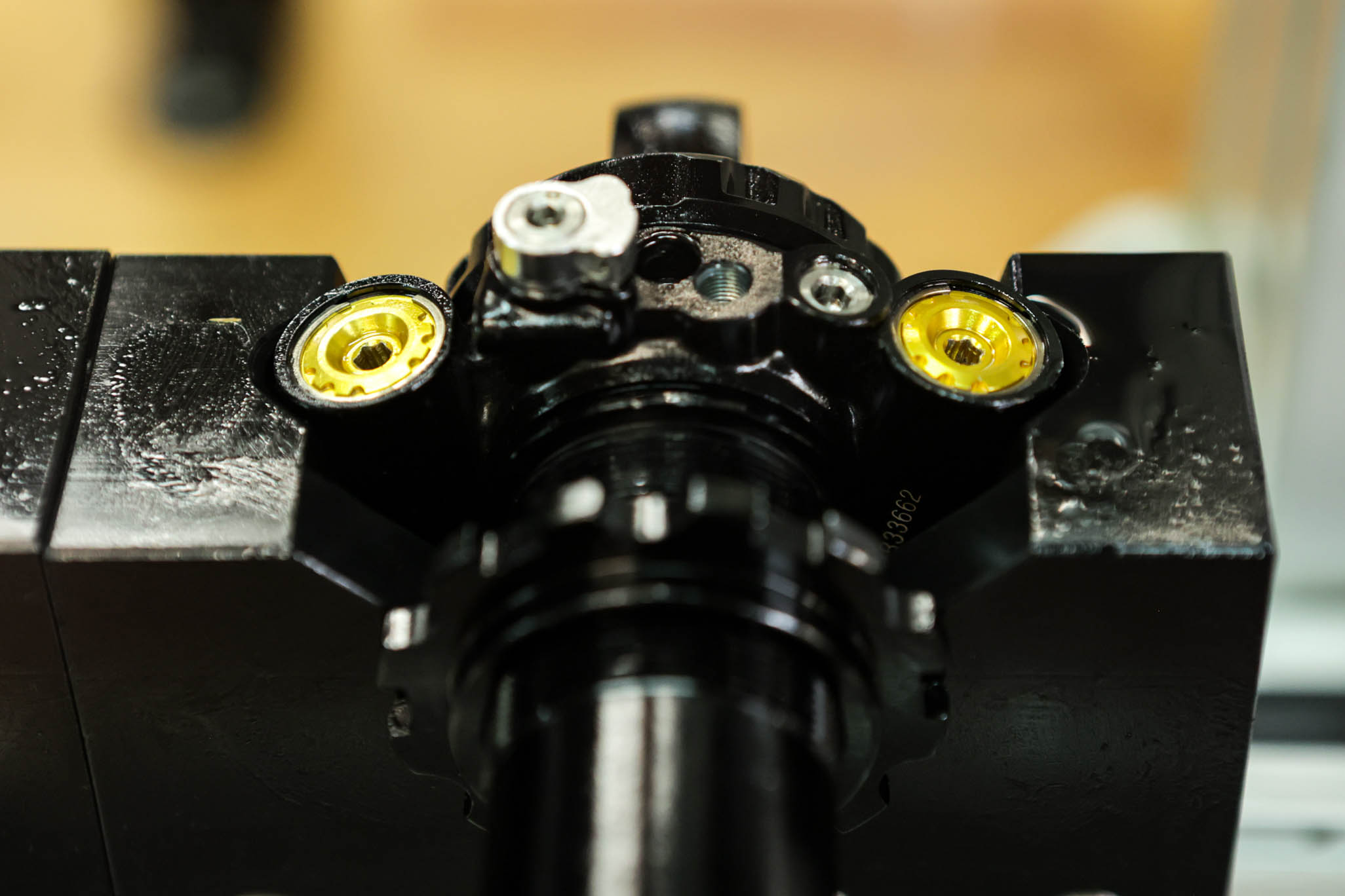
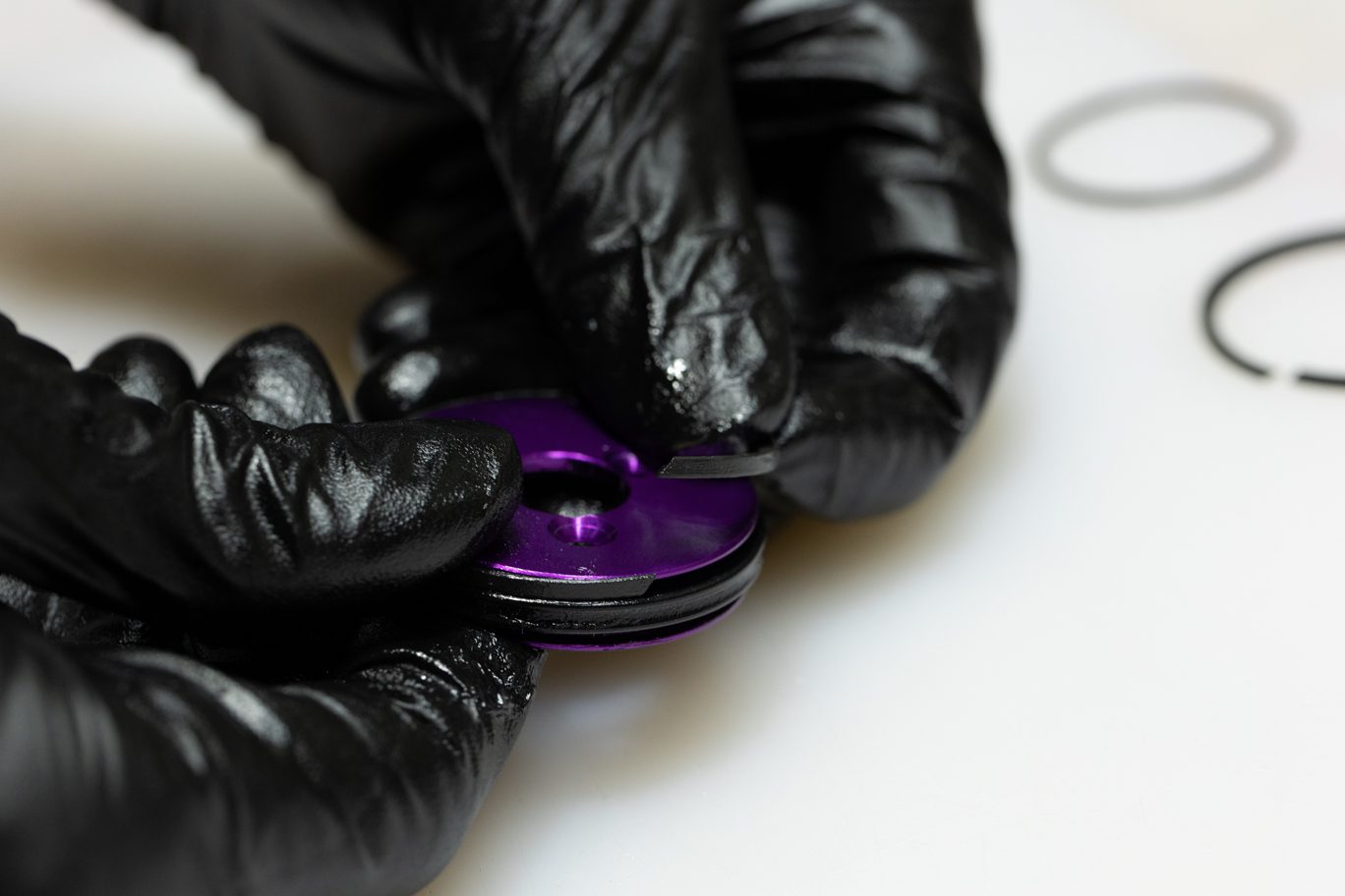
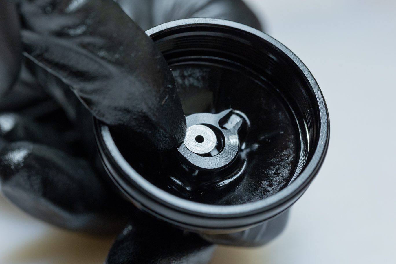
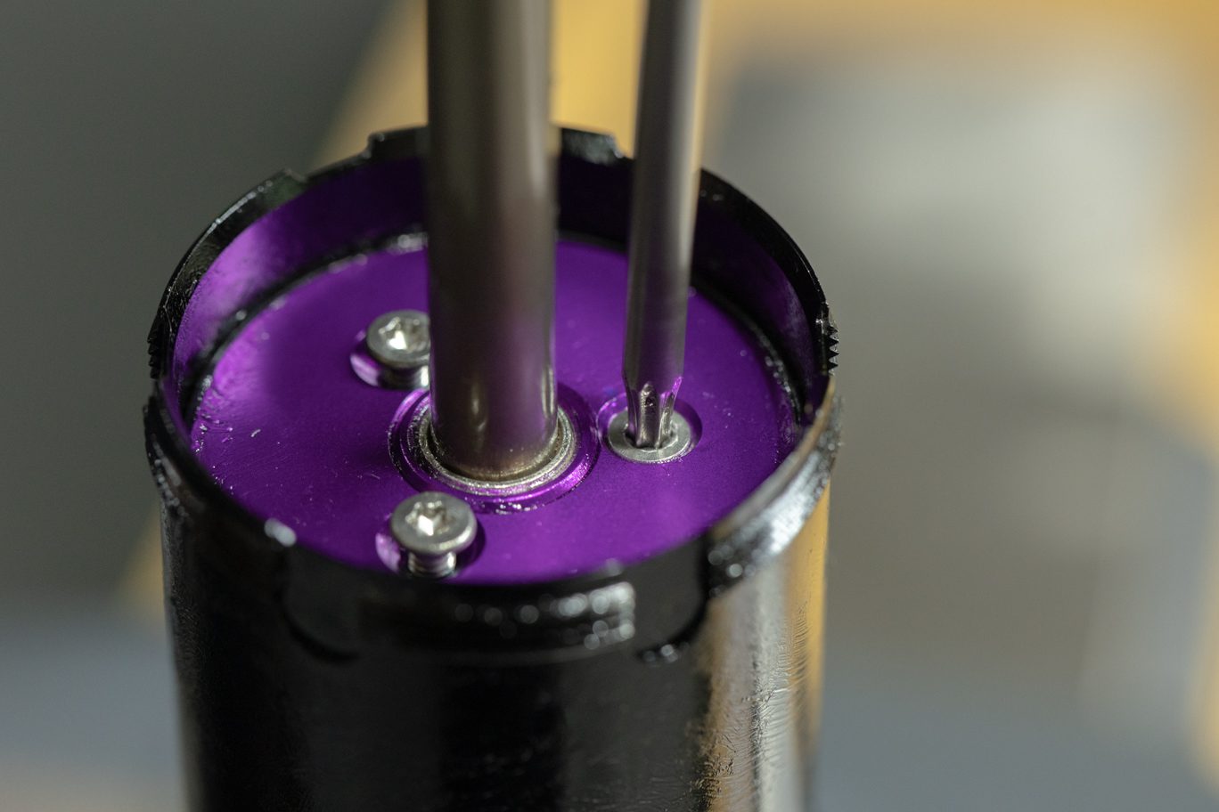
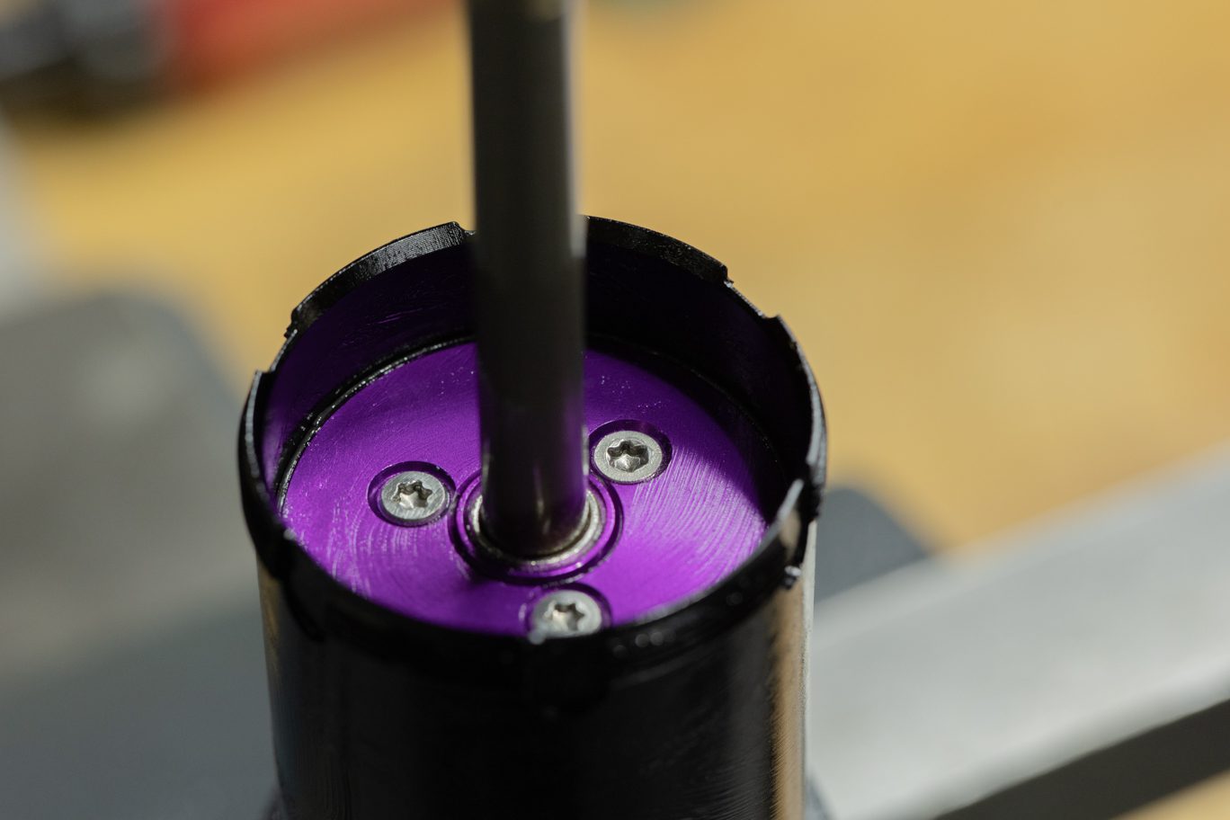
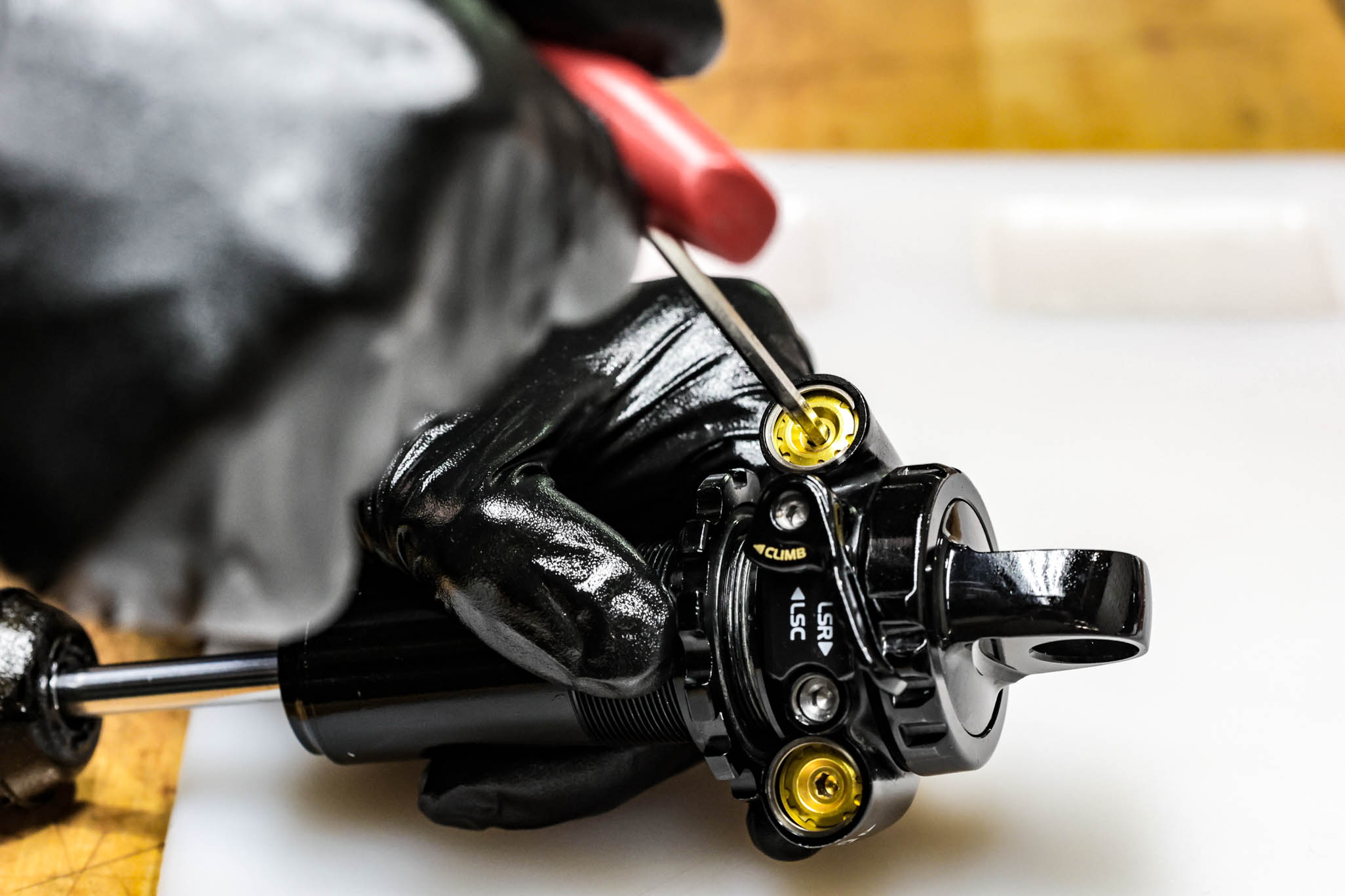
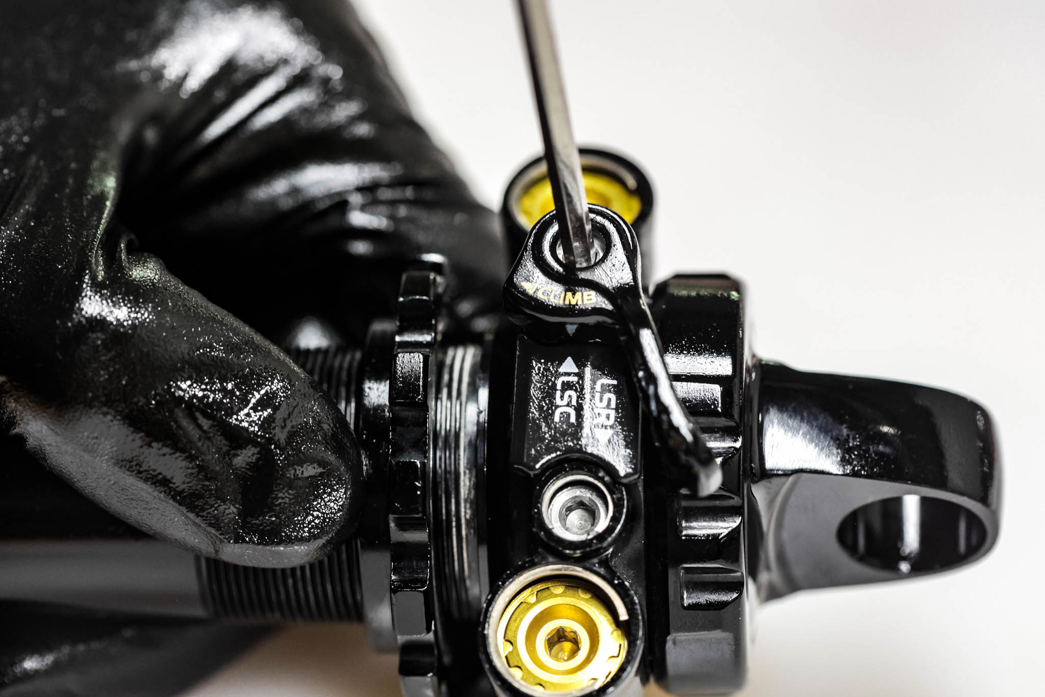
Unthread spool valve capture screw with 1.5mm Allen. Using 3mm Allen, dial High Speed adjusters in to gain access to High Speed circlips. Remove circlips. Back High Speed adjusters all the way out. Remove and discard o-rings on adjusters.
Note that the Compression spring is 20wt (silver), rebound is 30wt (black).
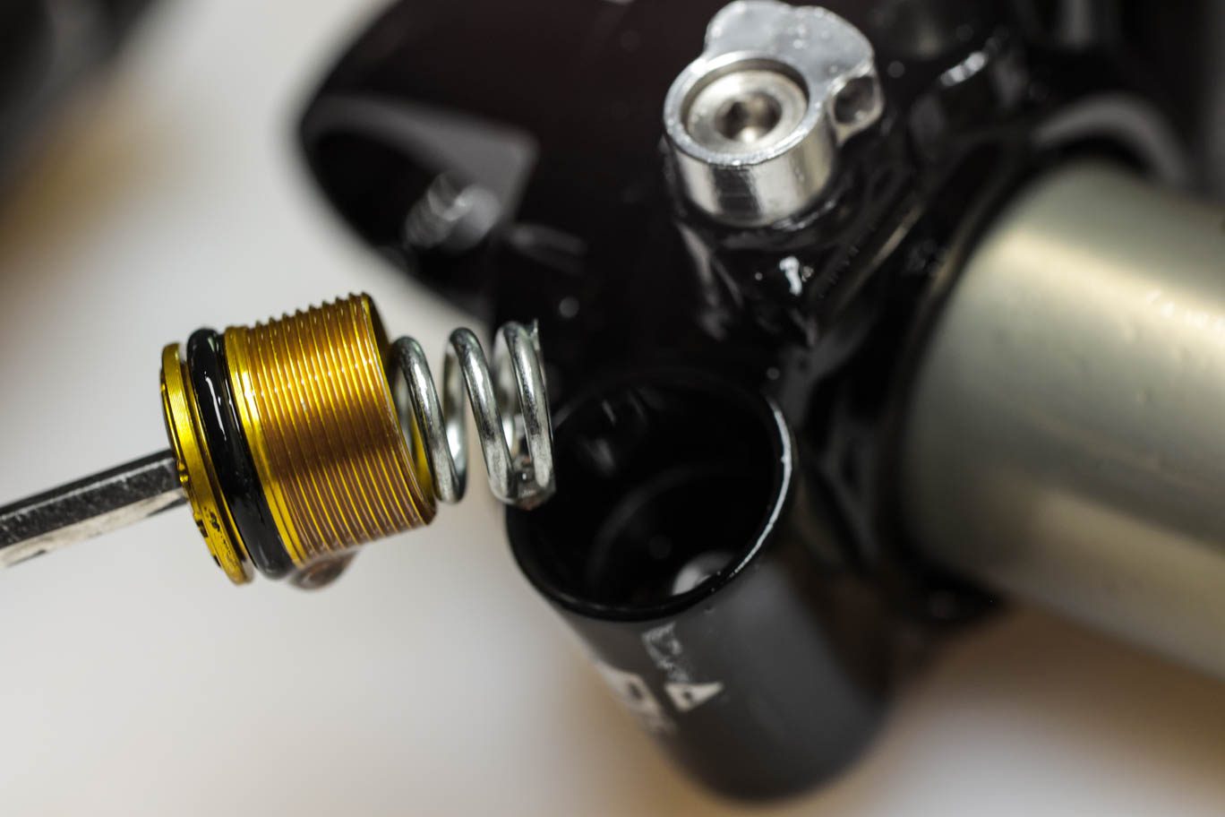
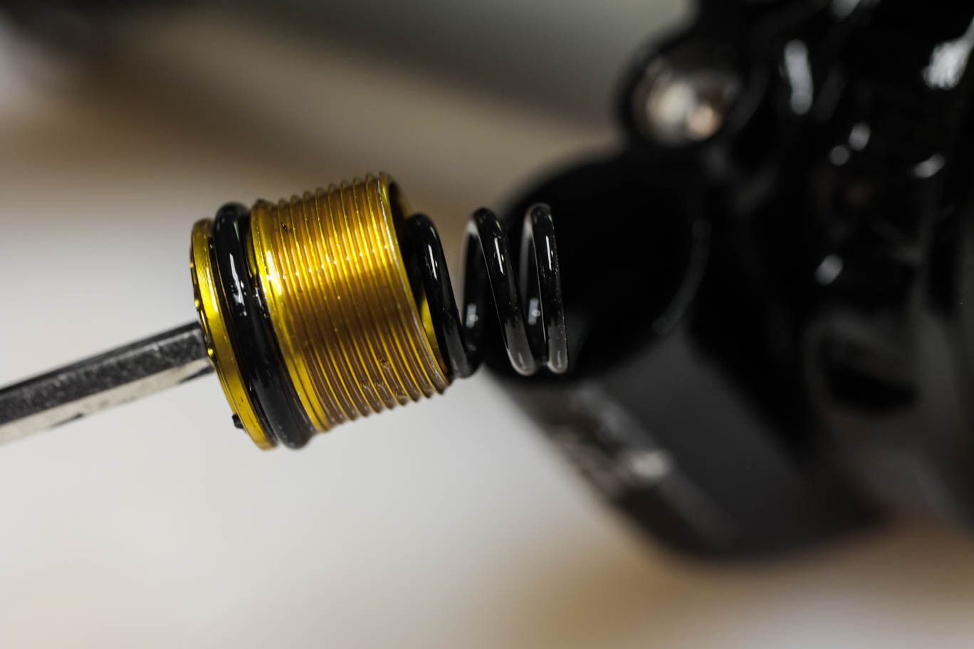
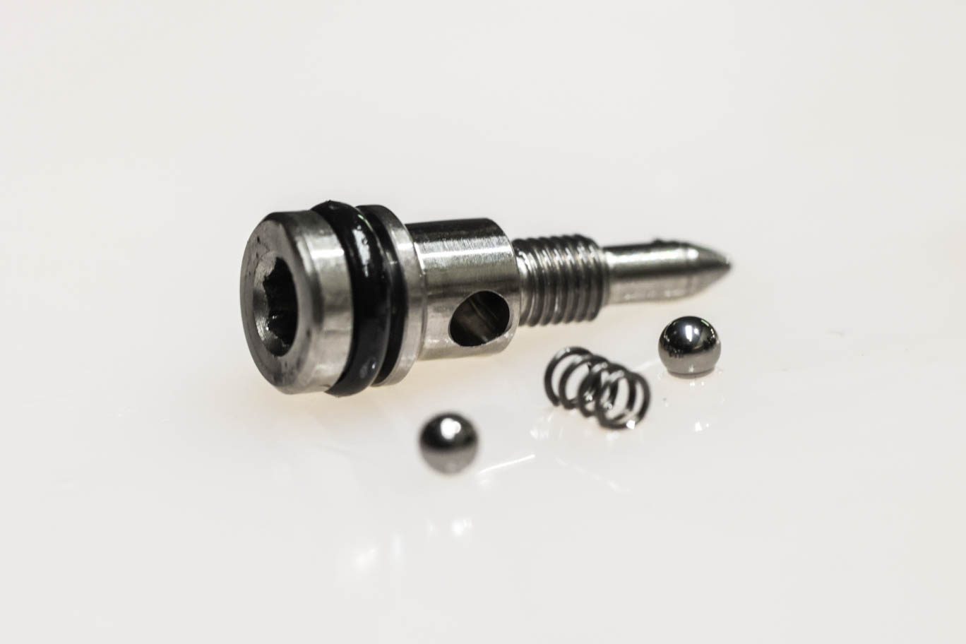
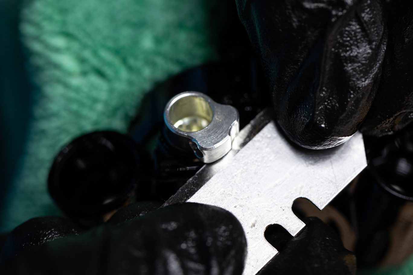
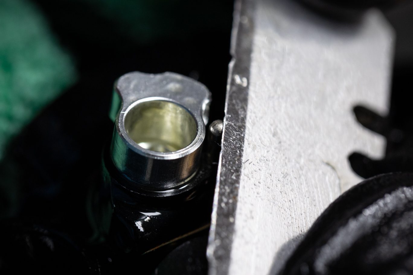
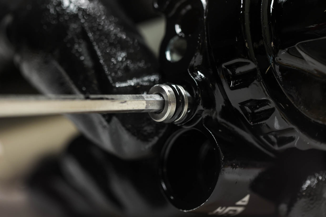
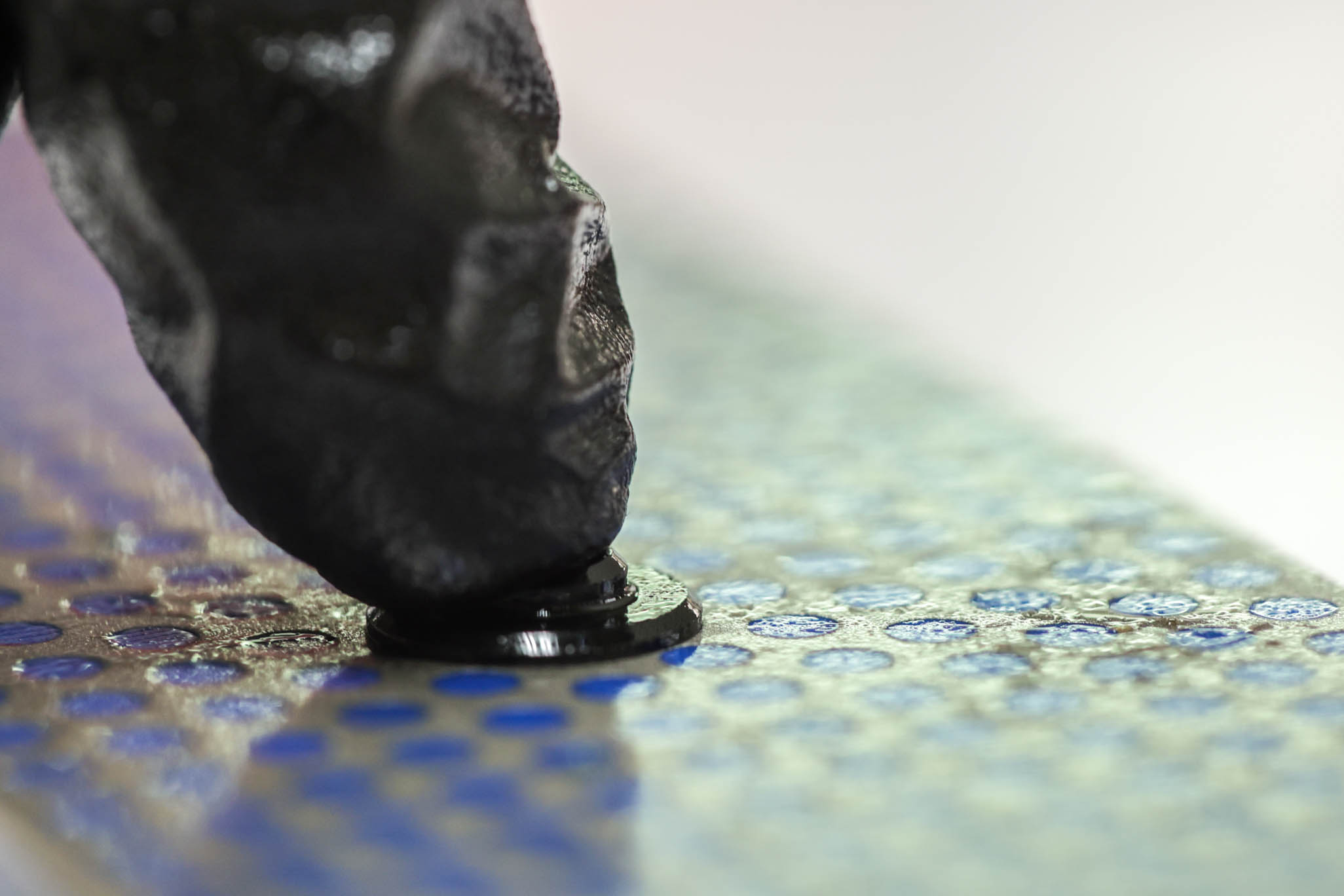
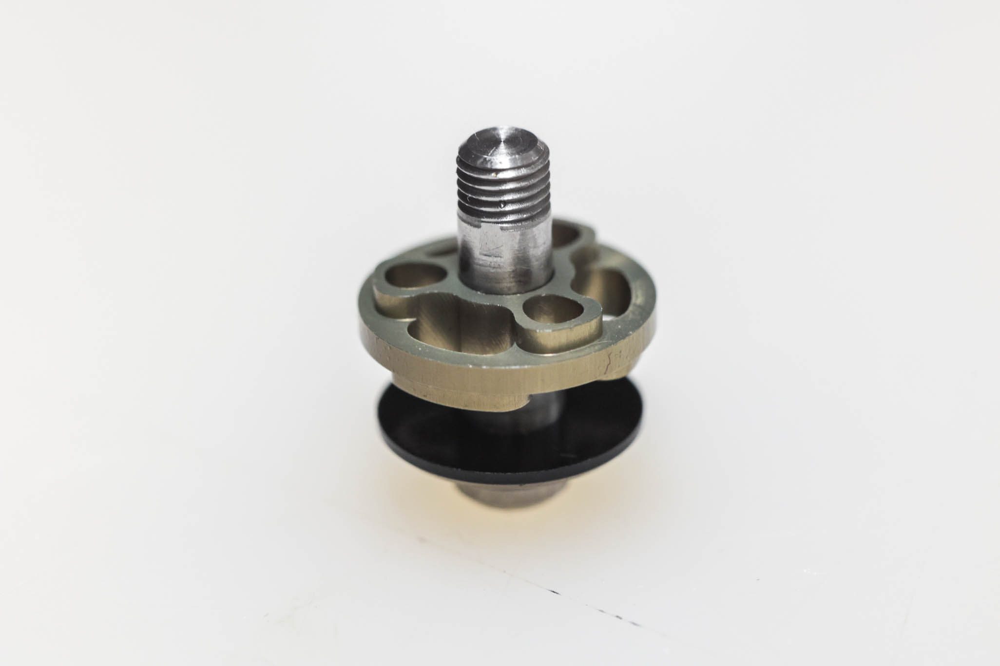
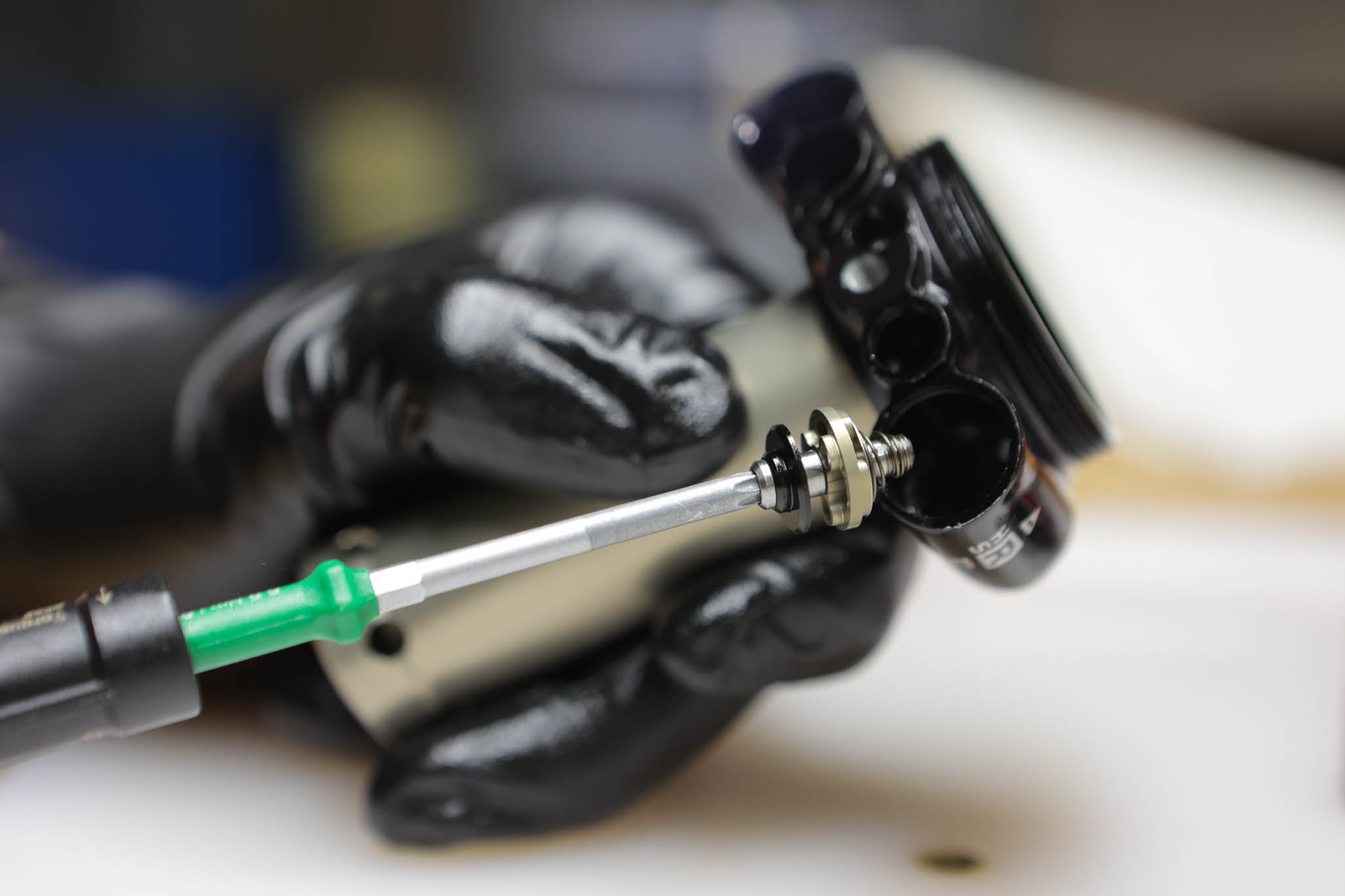
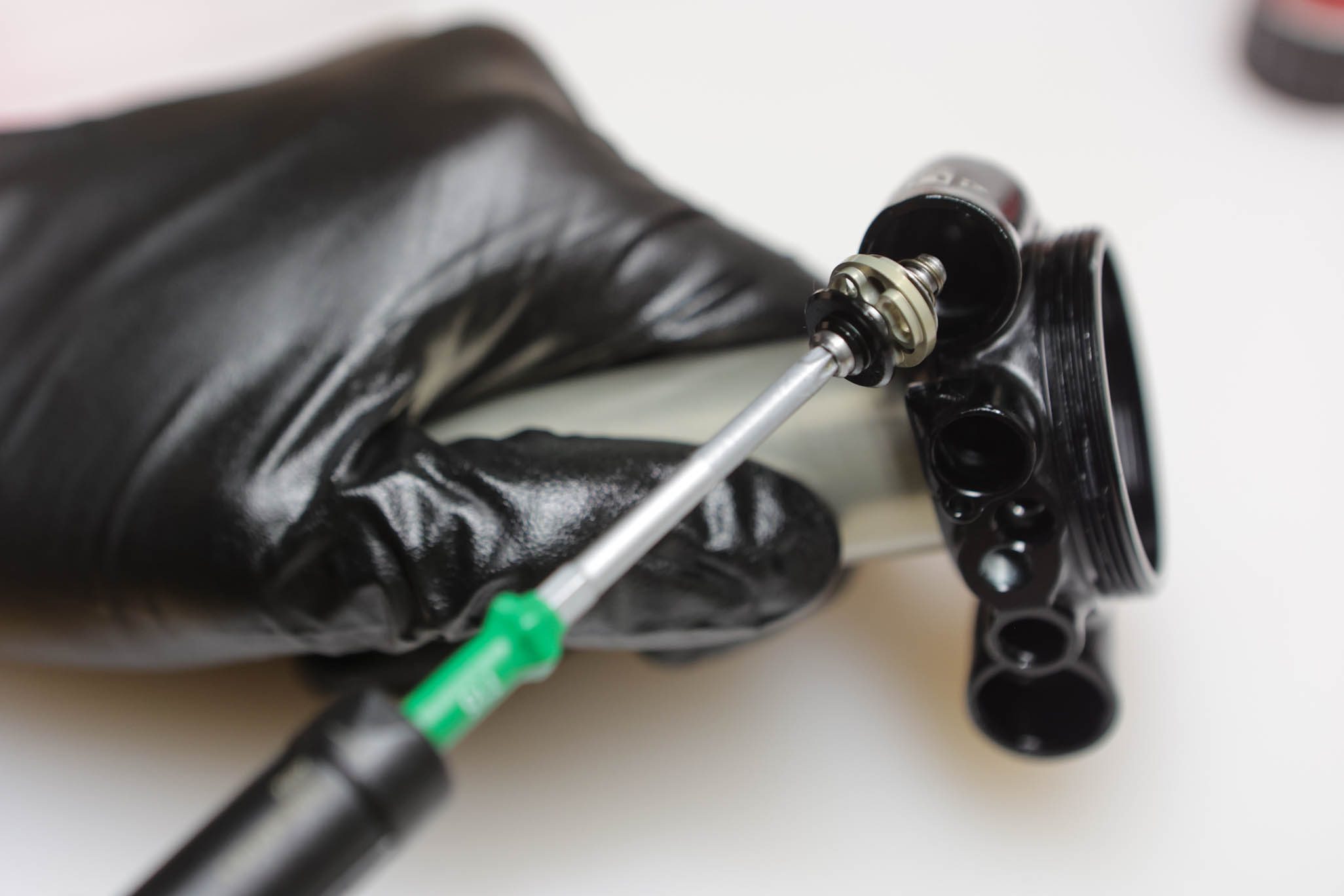
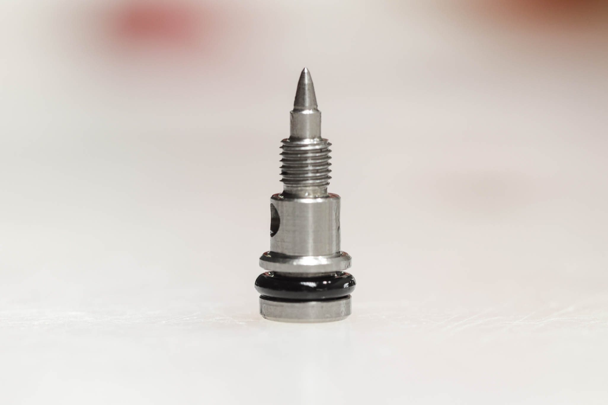
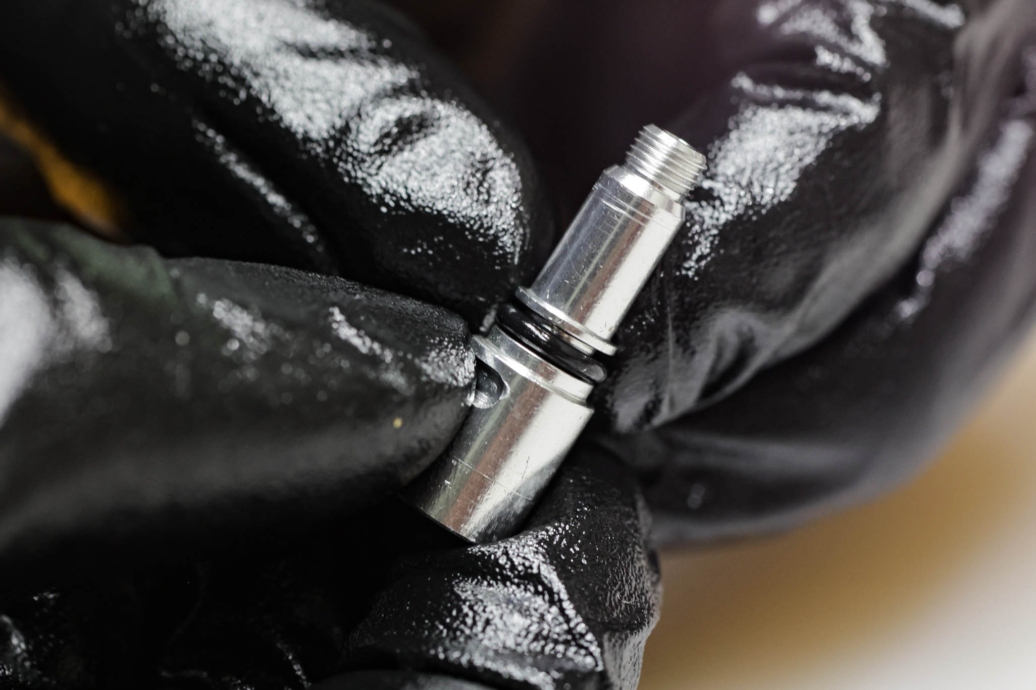
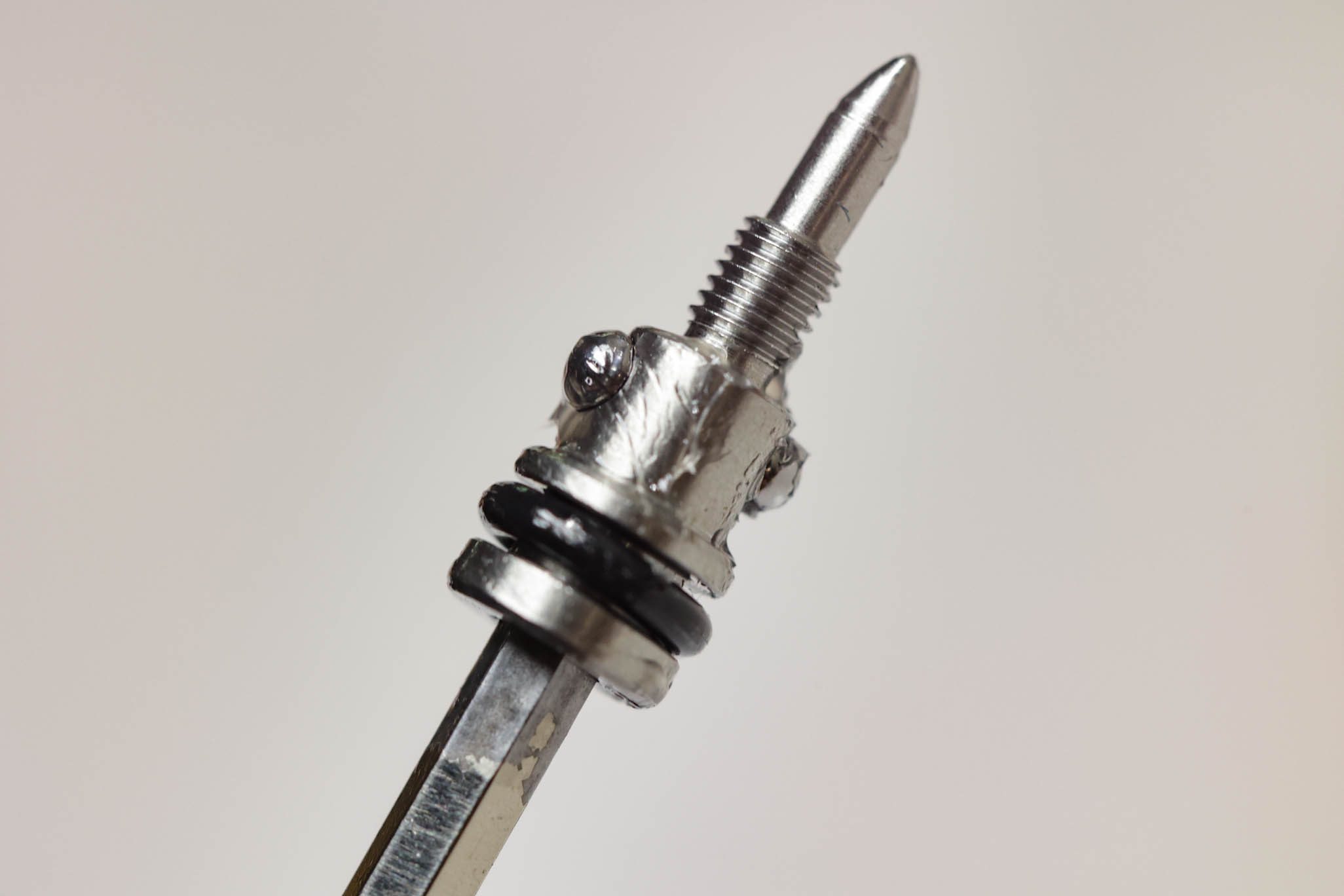
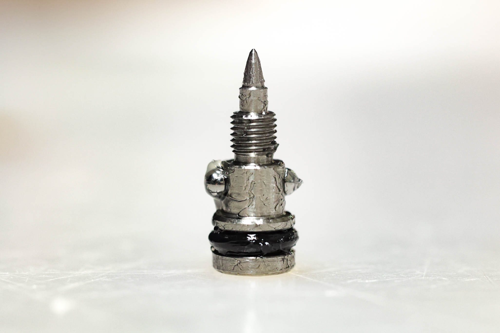
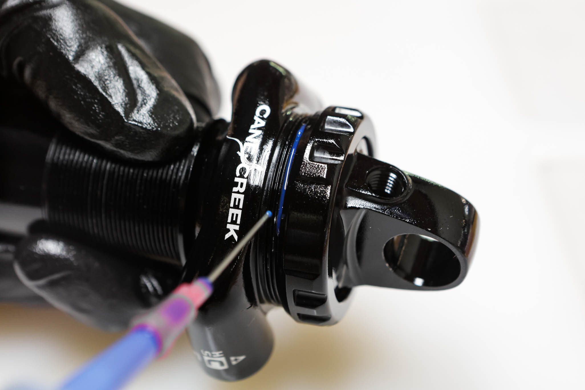
Unthread Low Speed Compression needle on spool valve with 3mm Allen and remove. Remove and discard o-rings on needle. Depress spool valve detent with razor blade to free spool valve. Remove detent and unthread spool valve. Remove and discard spool valve o-ring.
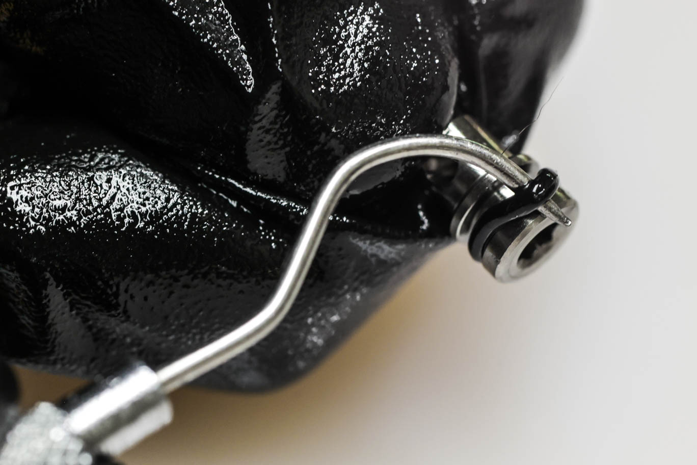
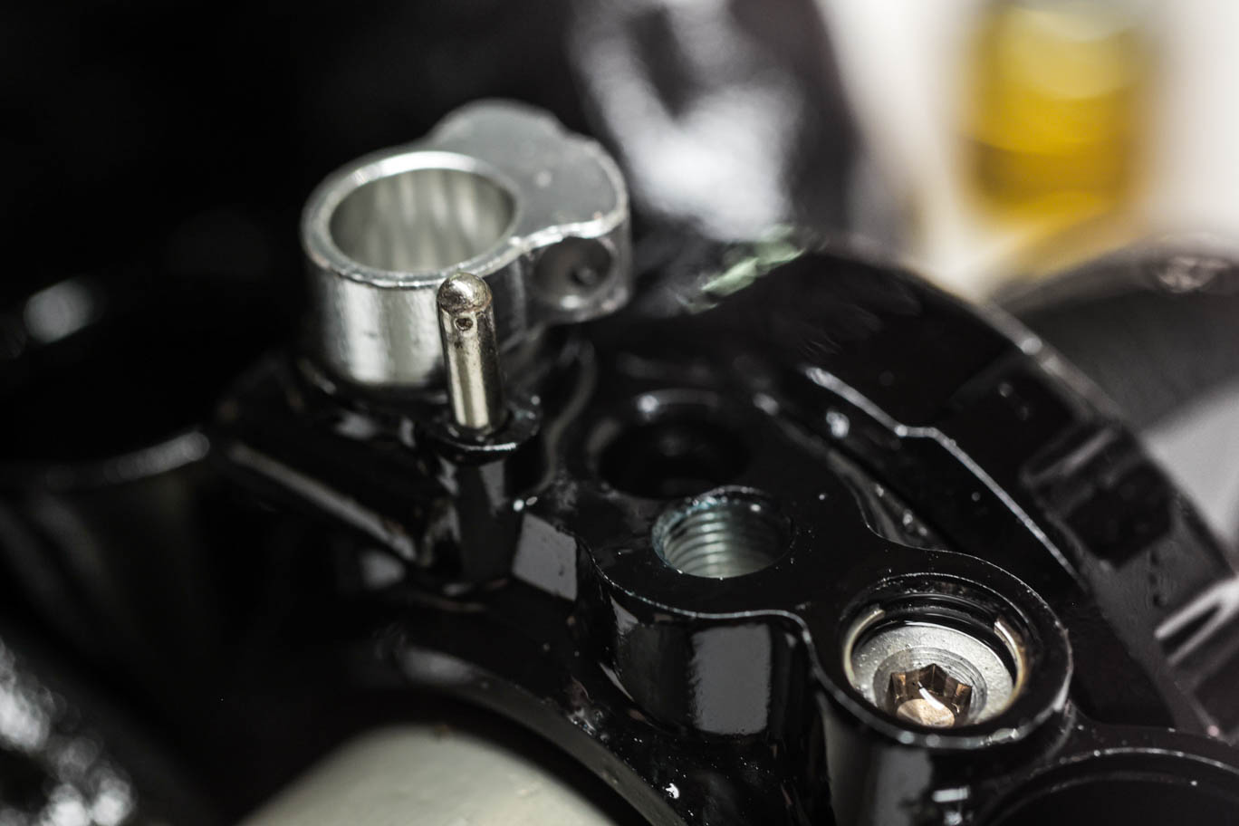
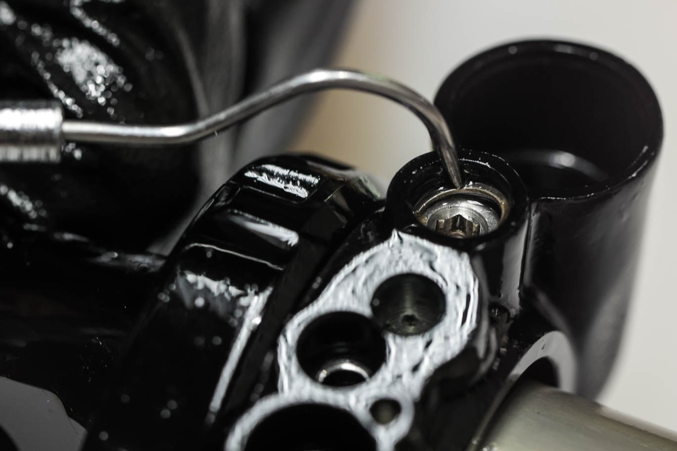
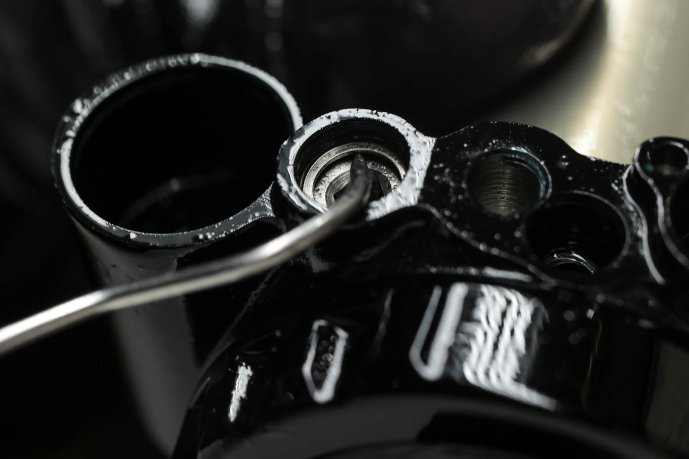
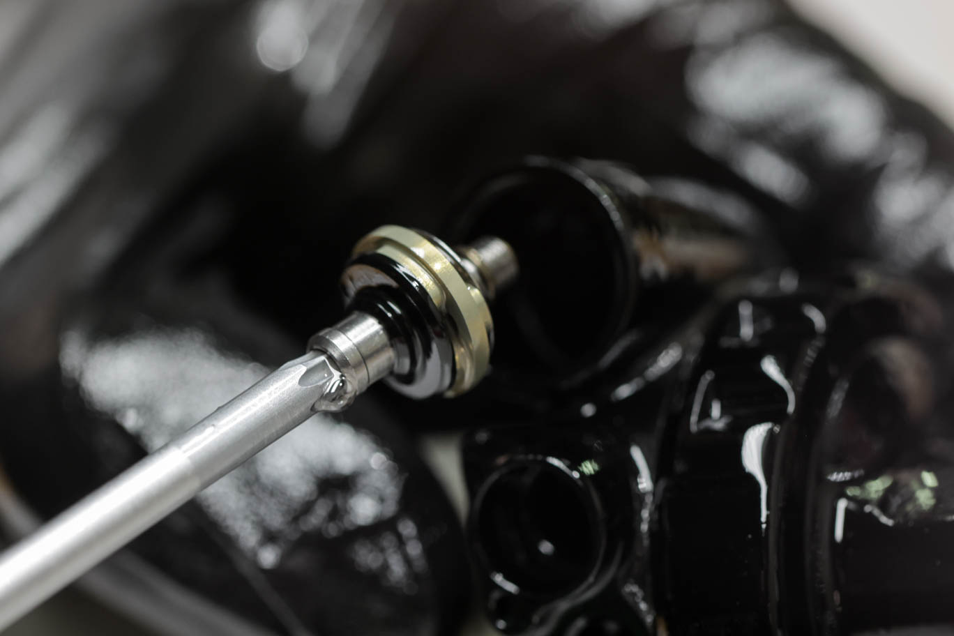
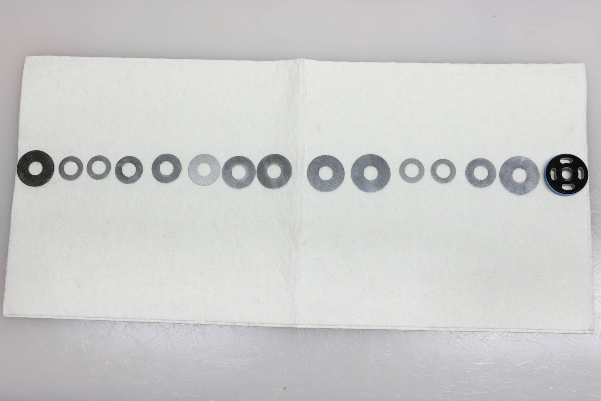
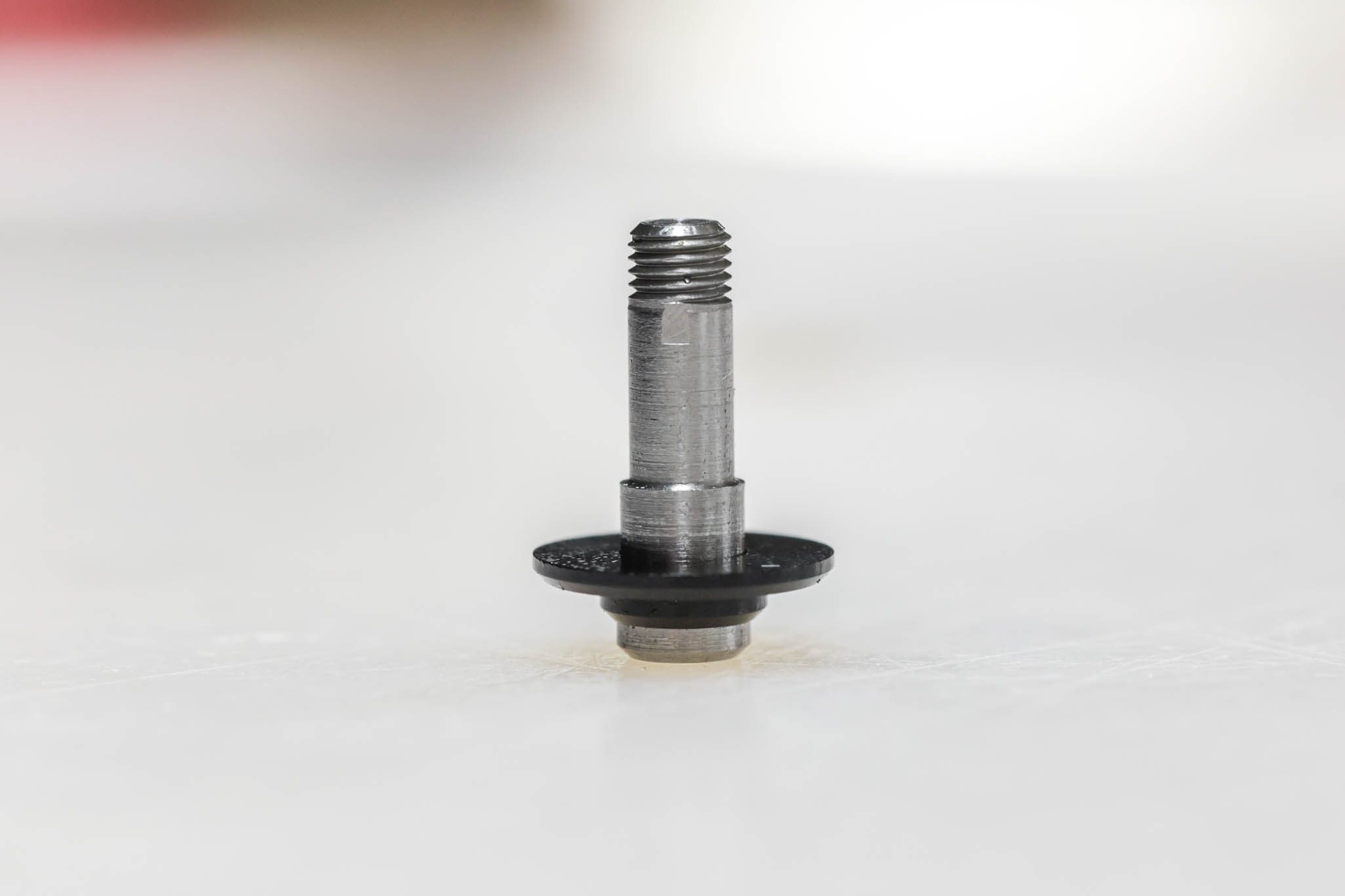
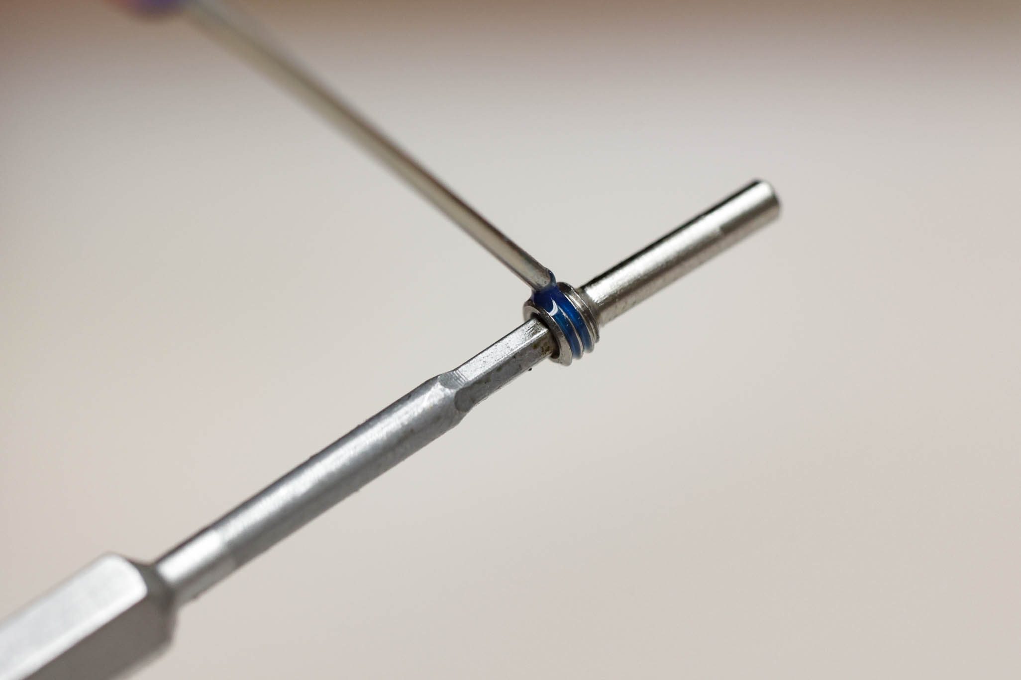
Gently bottom out Low Speed Rebound needle with 3mm Allen. Using pick, work circlip below retaining shelf all the way to needle. Back needle out 5-7 clicks and then rebottom needle to gain access to circlip. Using pick centered on circlip, pry up diagonally to pull circlip past shelf and remove. Unthread and remove needle. Remove and discard o-ring.
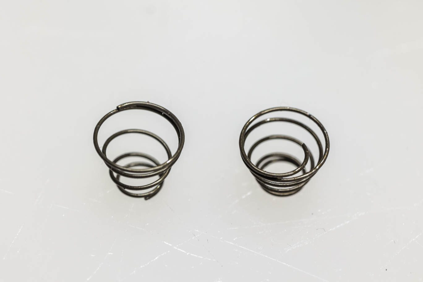
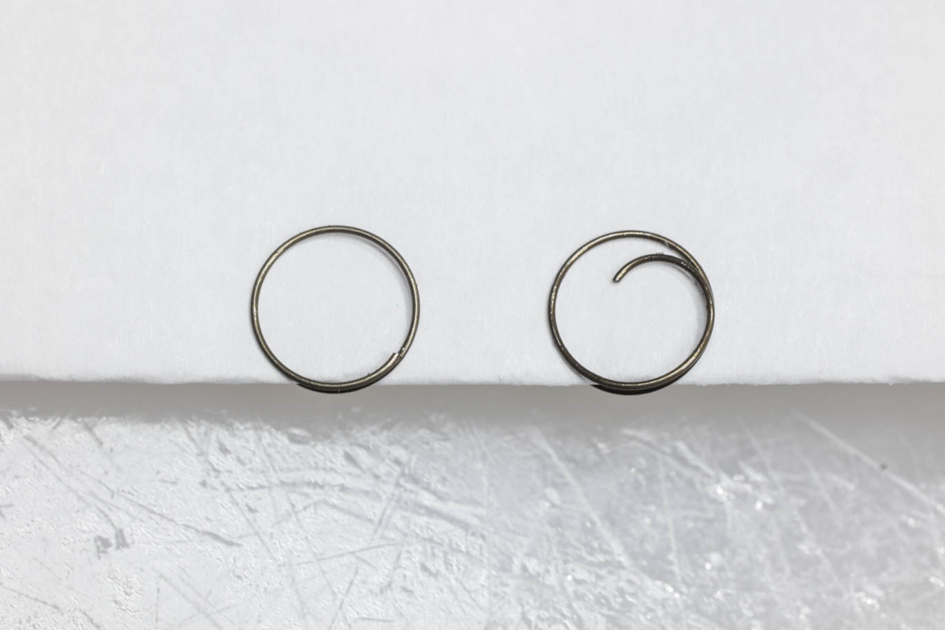
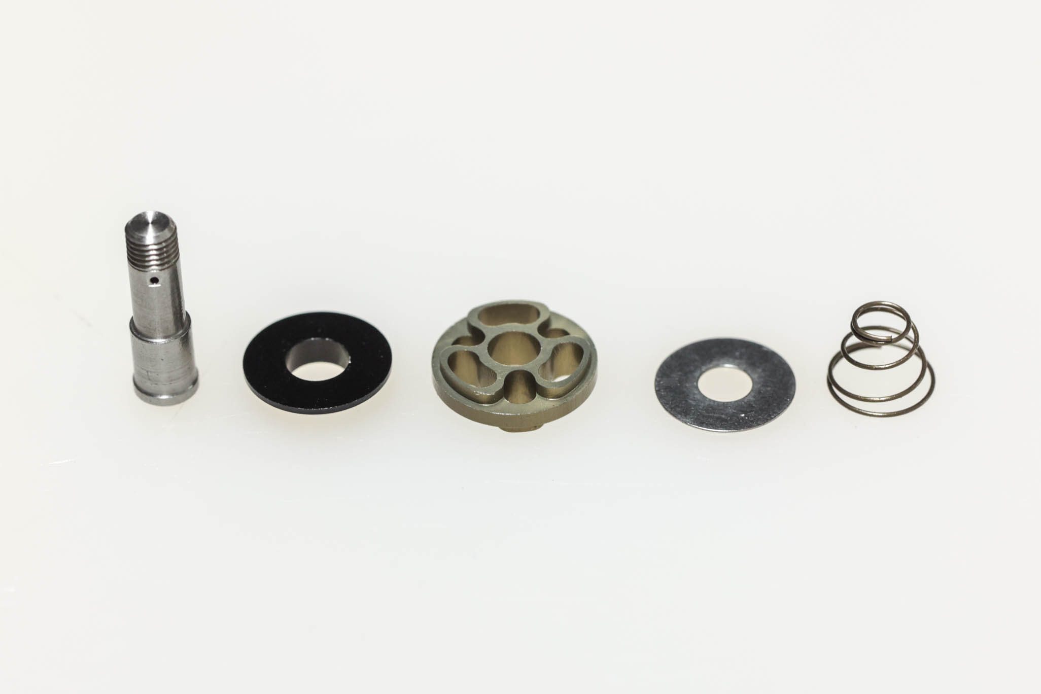
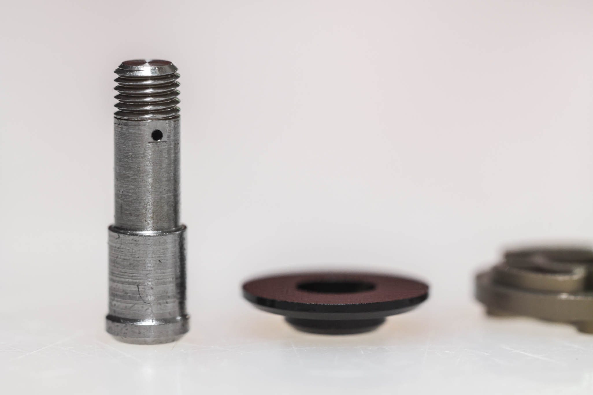
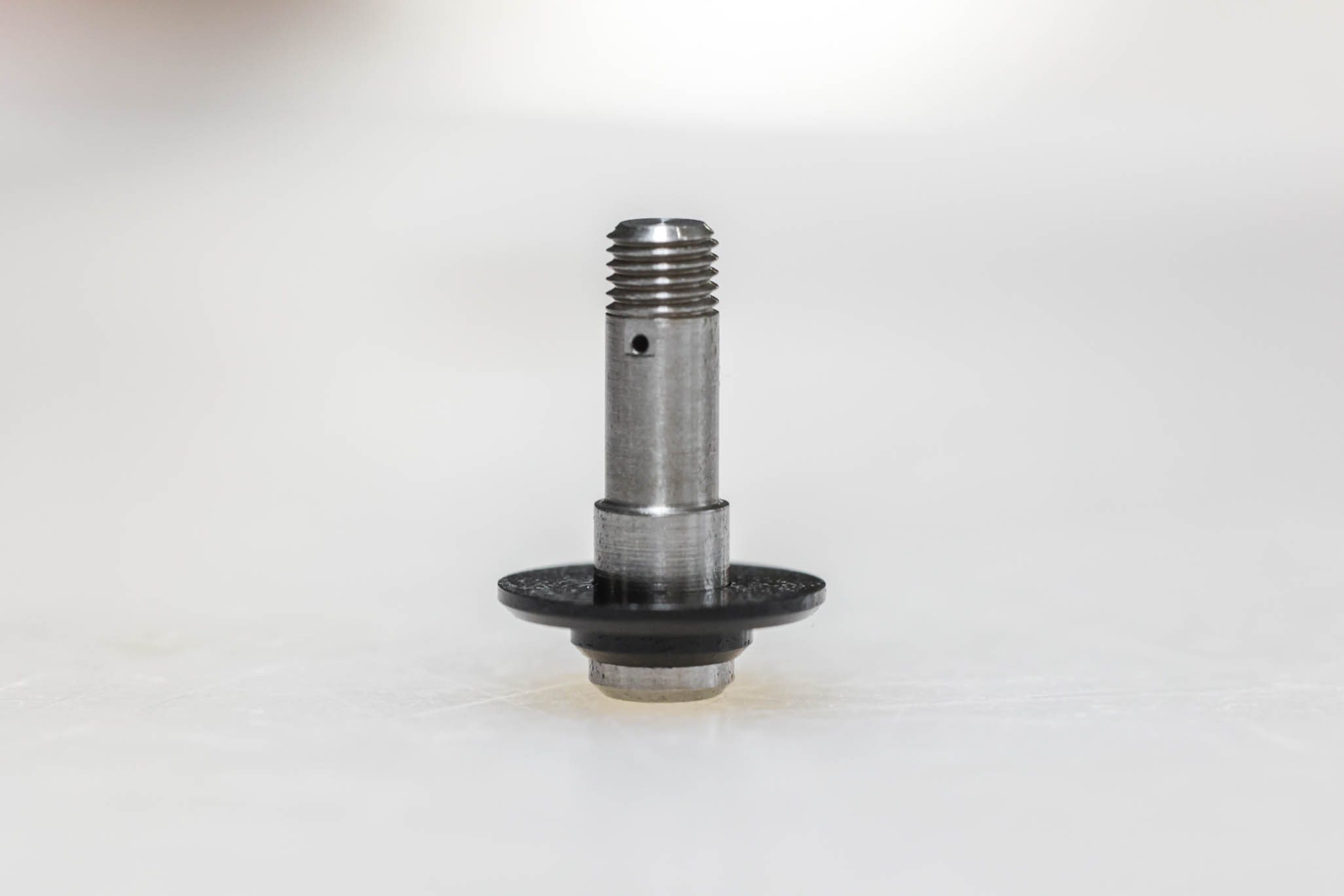
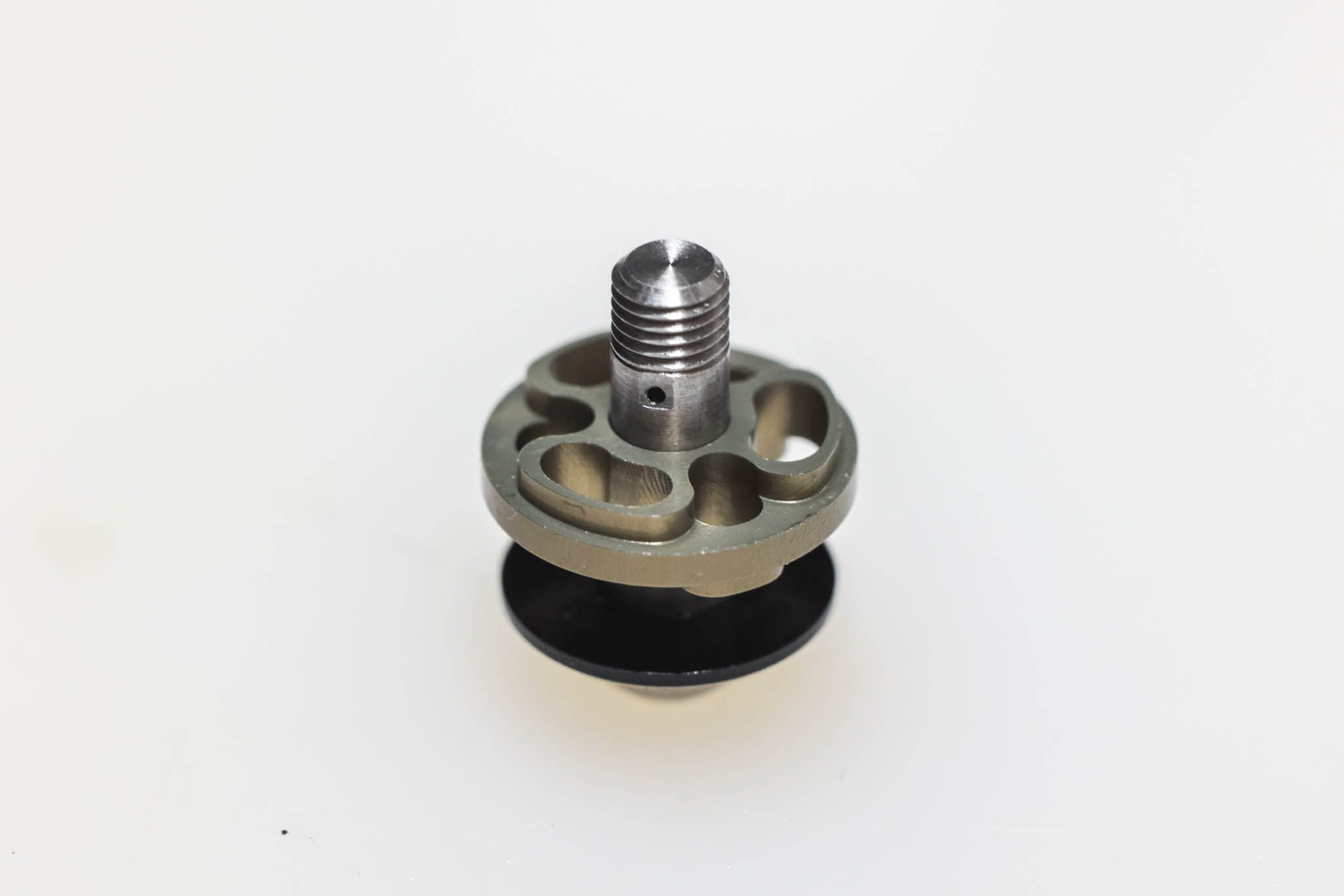
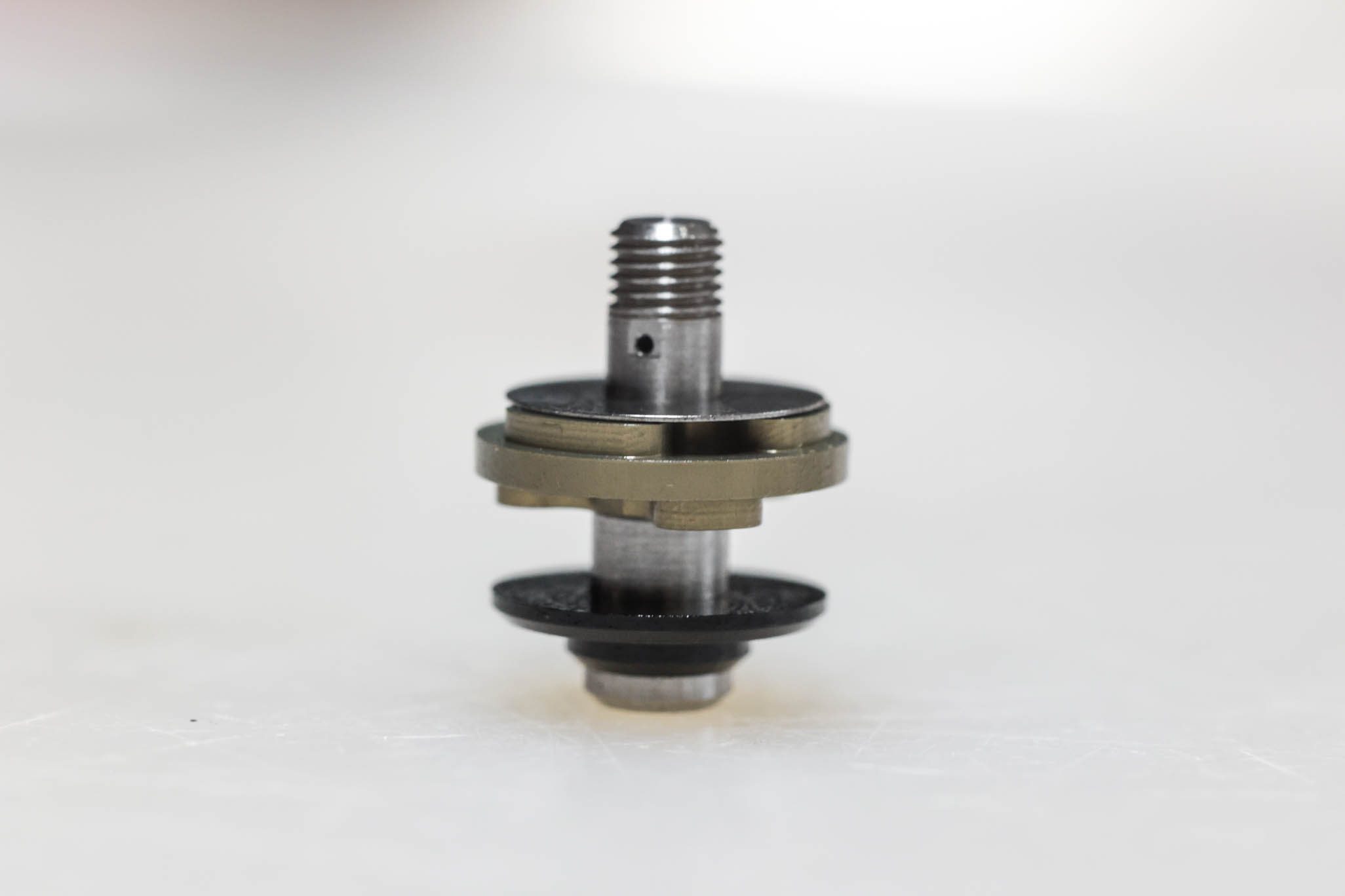
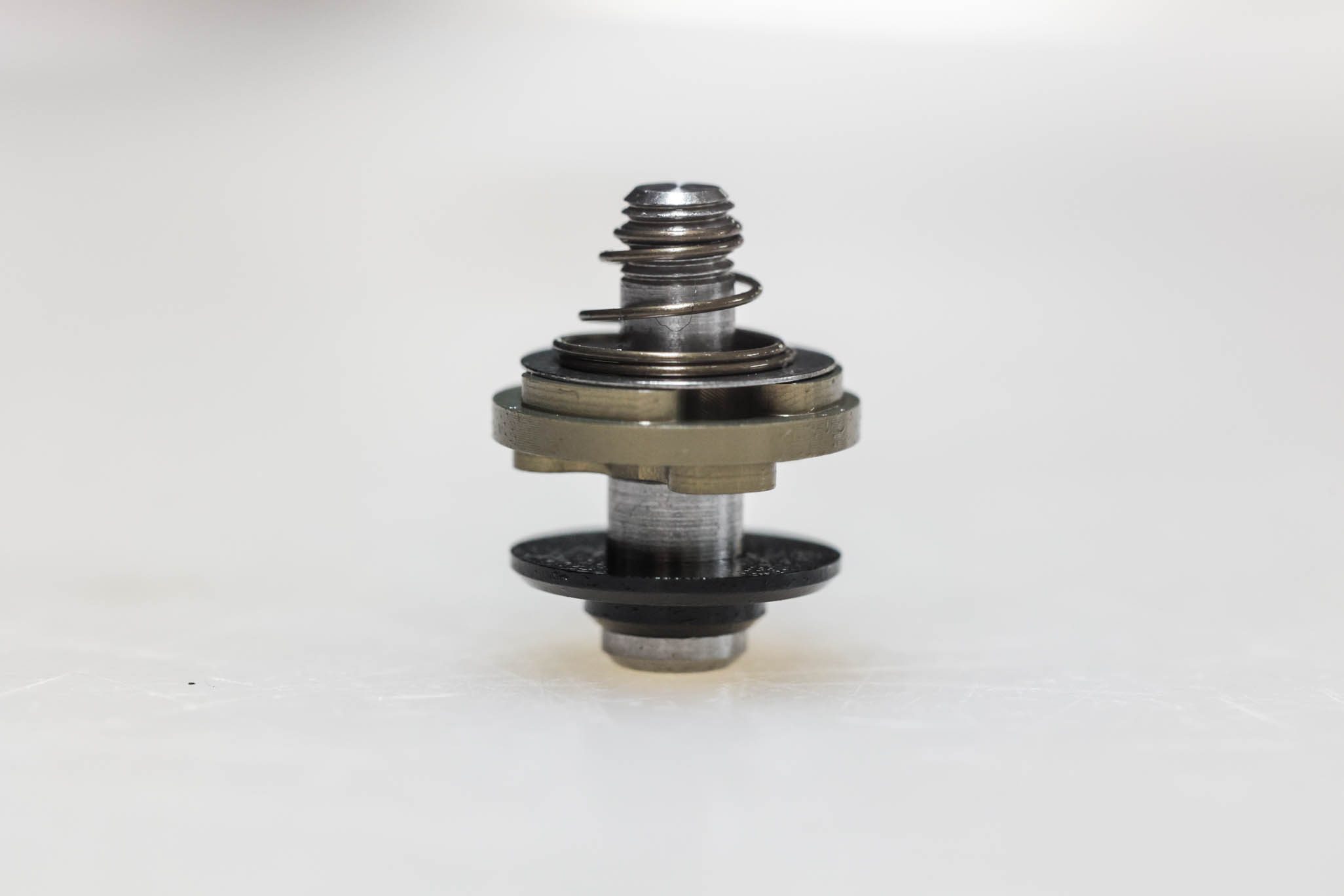
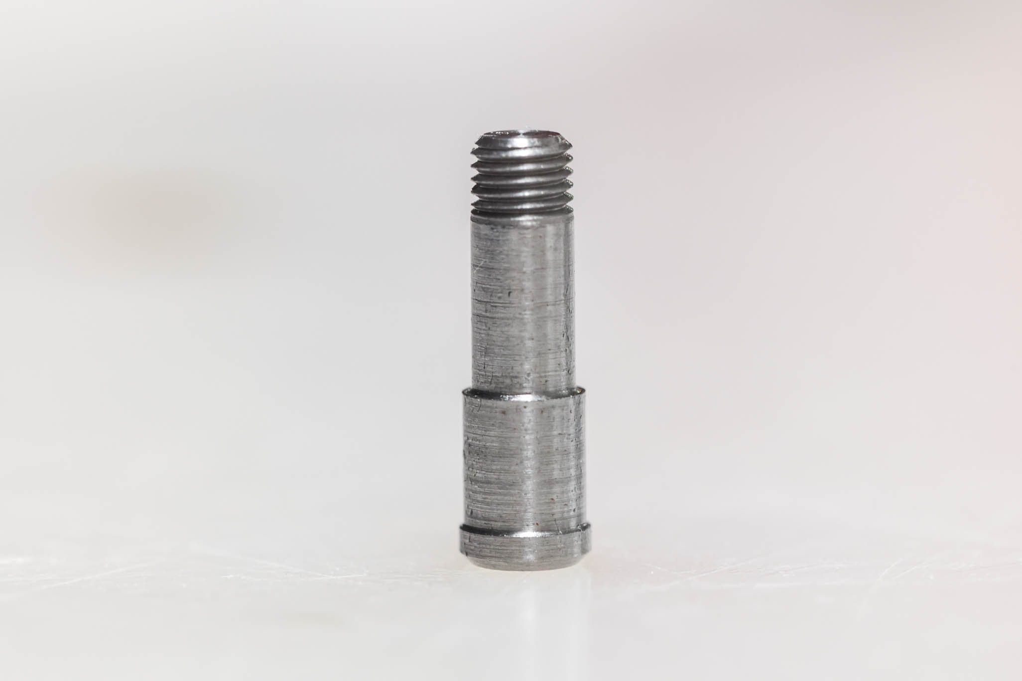
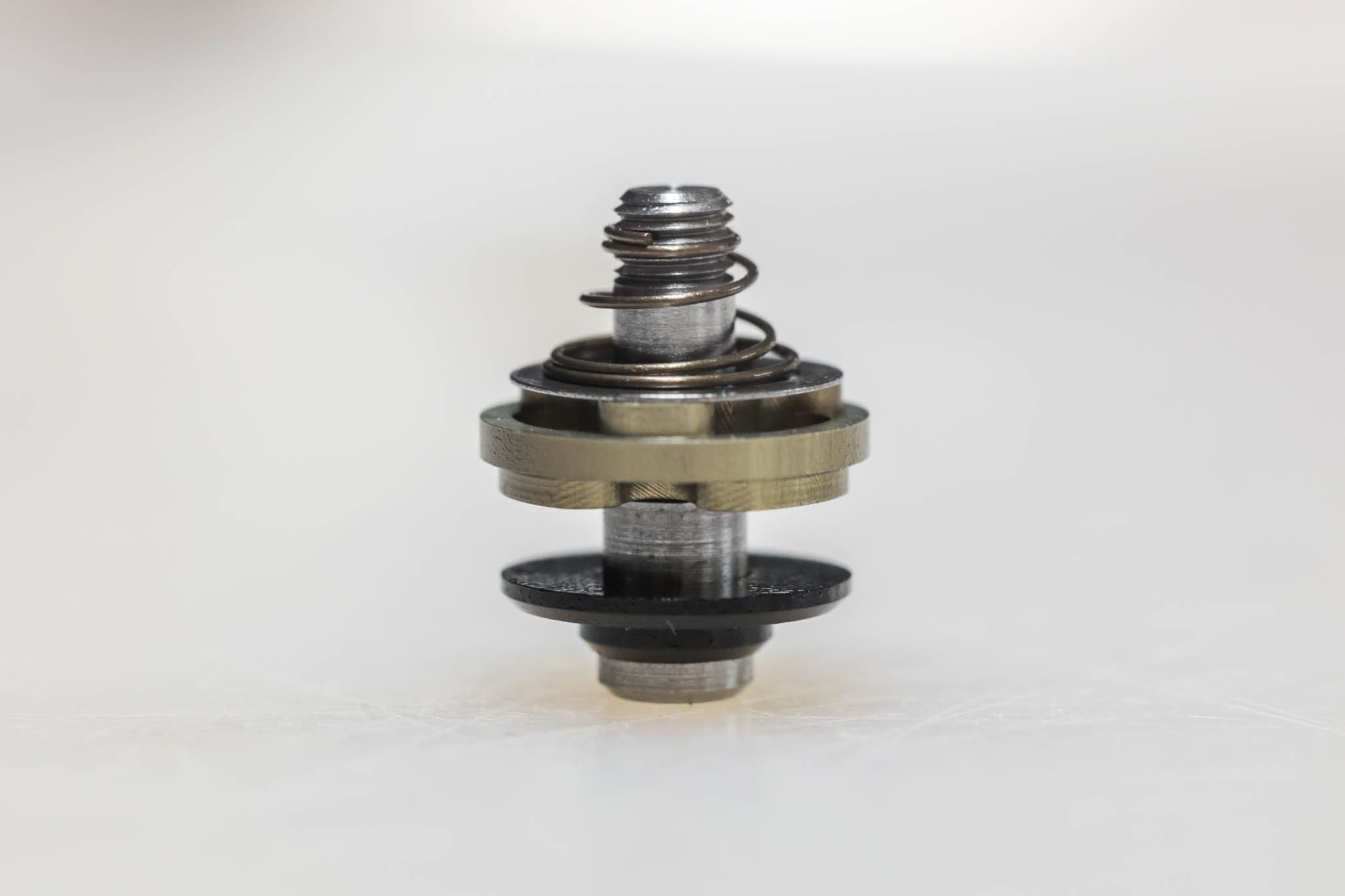
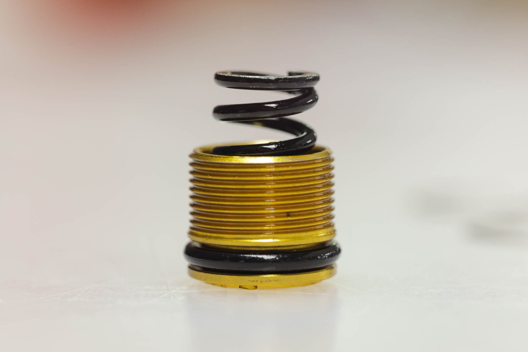
TSN service is not required as part of a standard IL service. However, if the shock exhibits any audible sounds, usually a “chirp”, during use, this could be related to a bent TSN spring. No additional parts are required to do the TSN service.
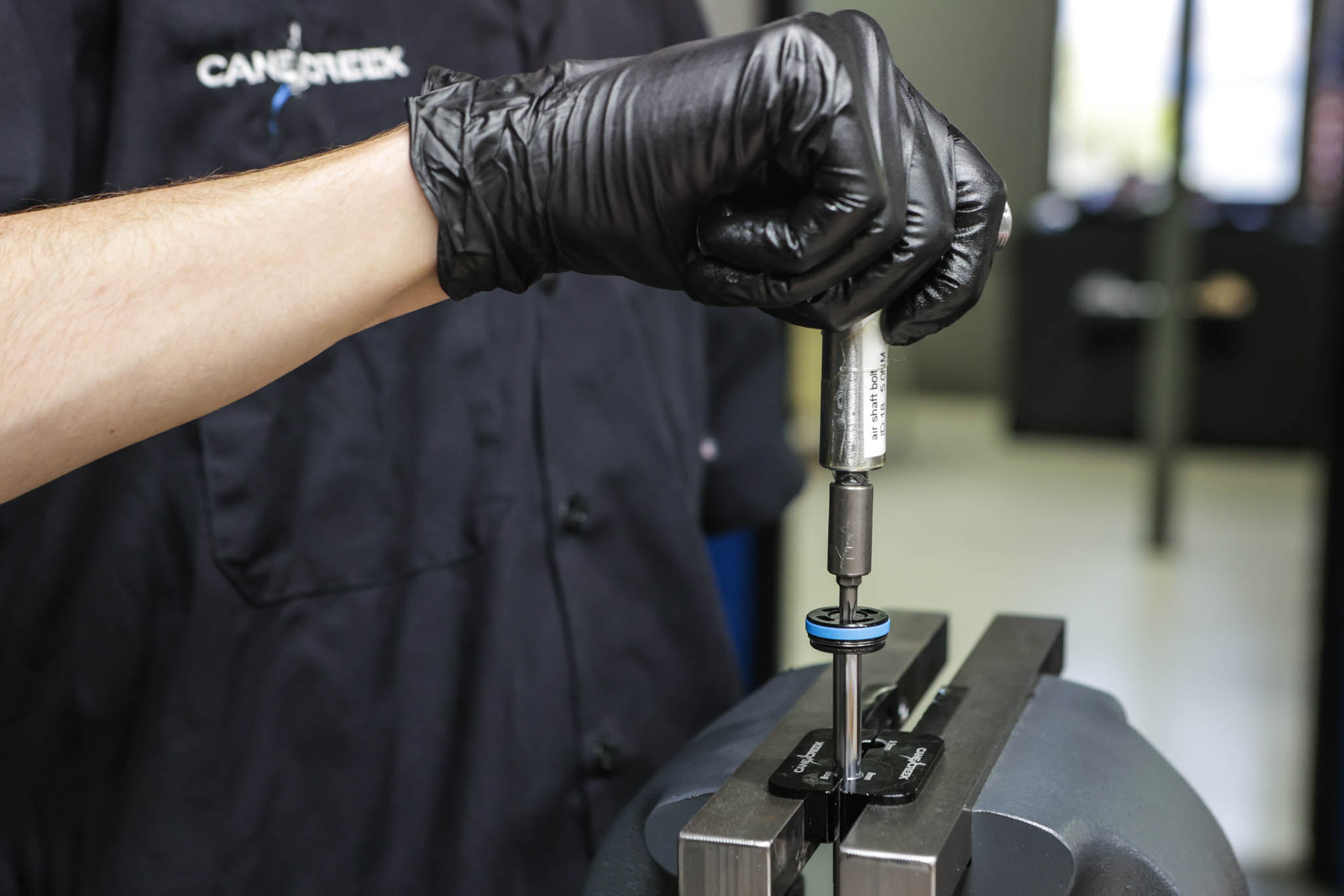
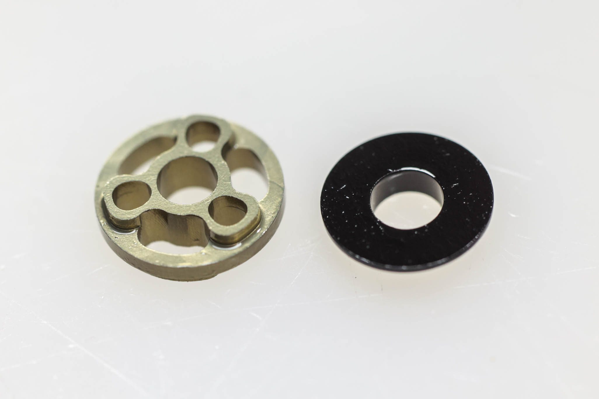
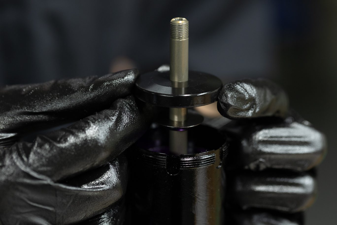
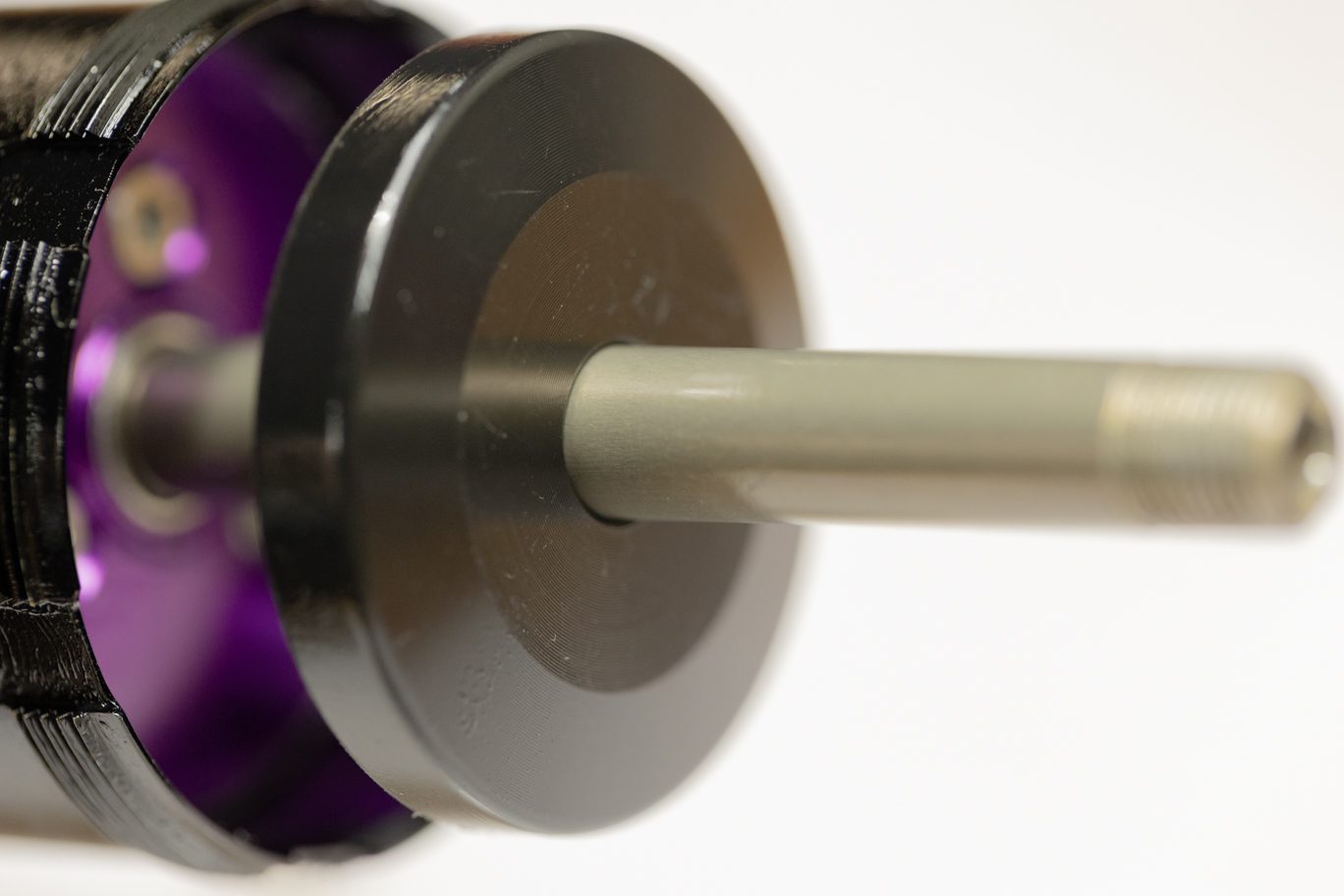
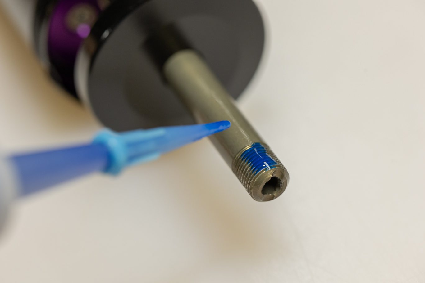
Reassemble shim stack, flipping face shim if necessary, and reinstall stop washer, shim stack and piston on shaft. Add one drop of blue Loctite (243) on the shaft threads. Install shaft bolt with T25. Torque to 5 Nm.
When installing the piston bolt, keep downward pressure on the piston with your other hand to prevent any Loctite from getting between the piston and face shim.
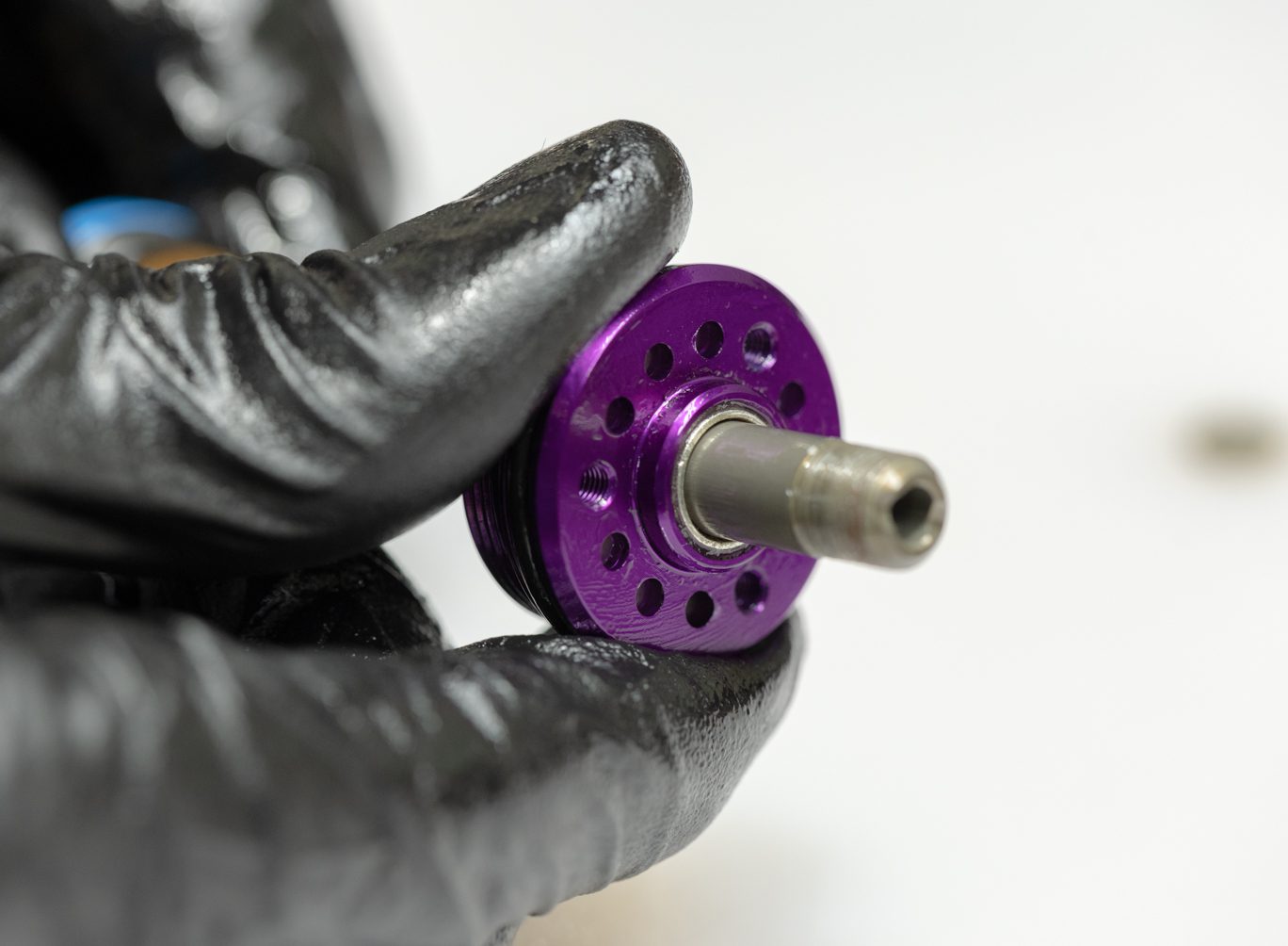
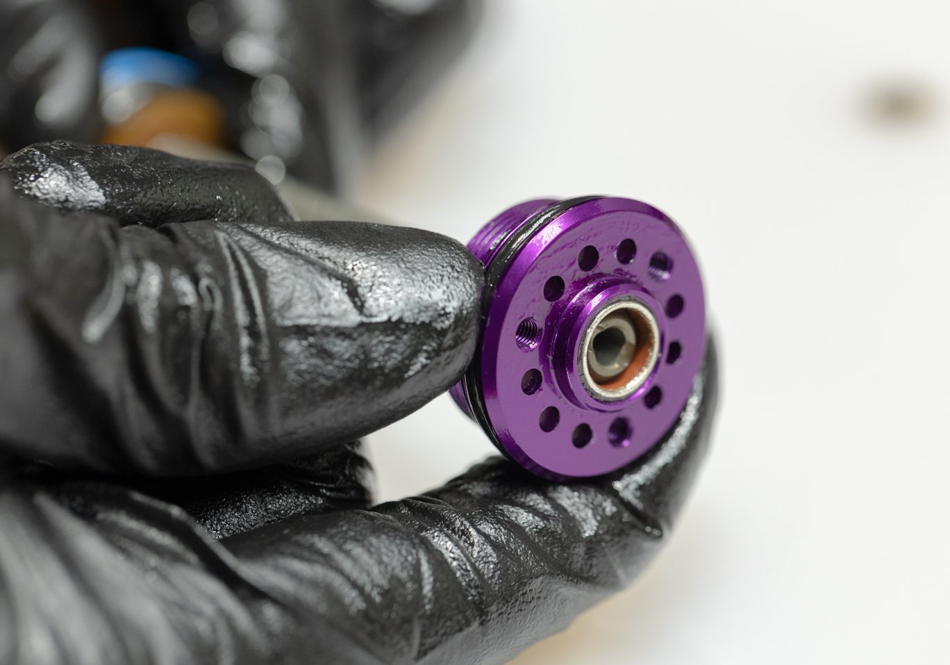
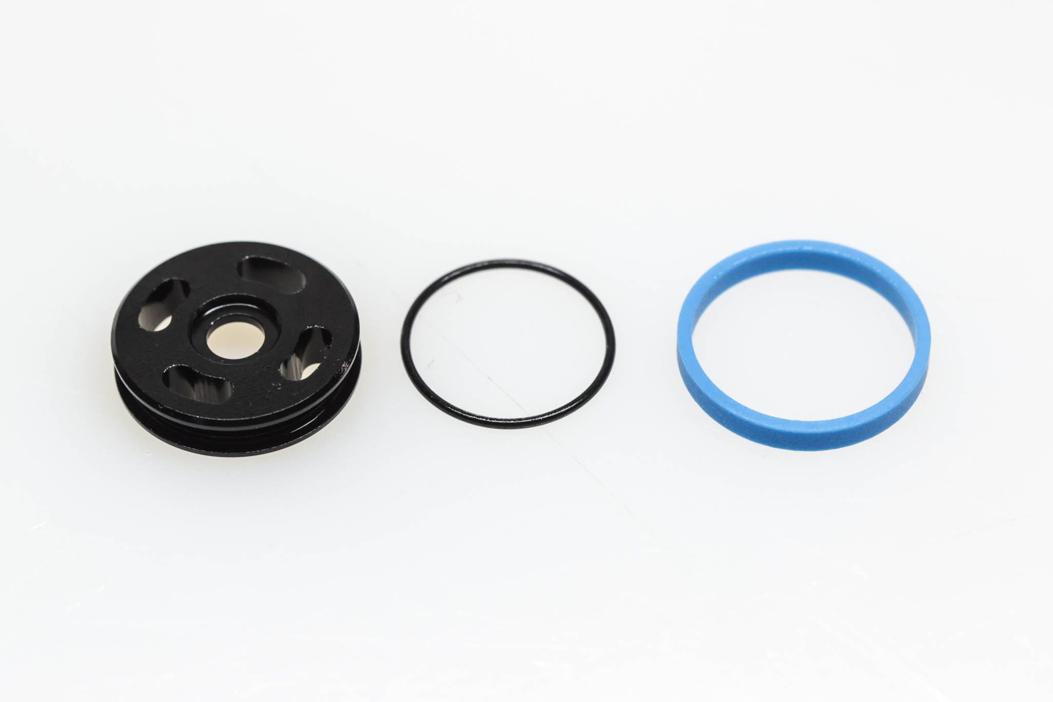
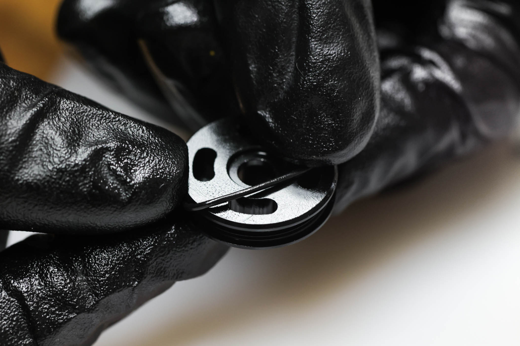
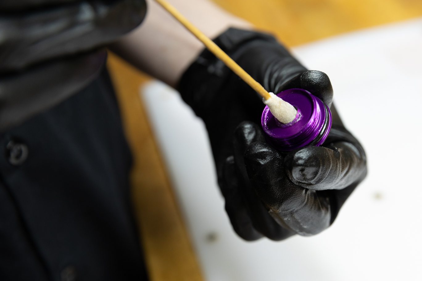
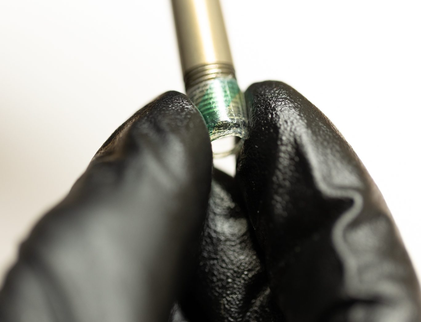
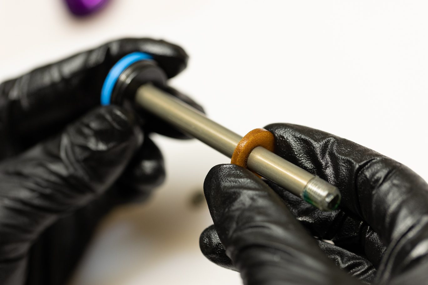
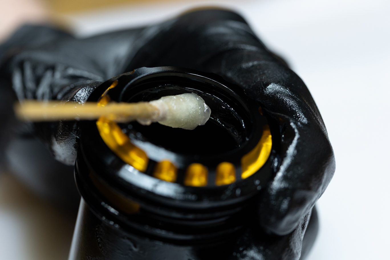
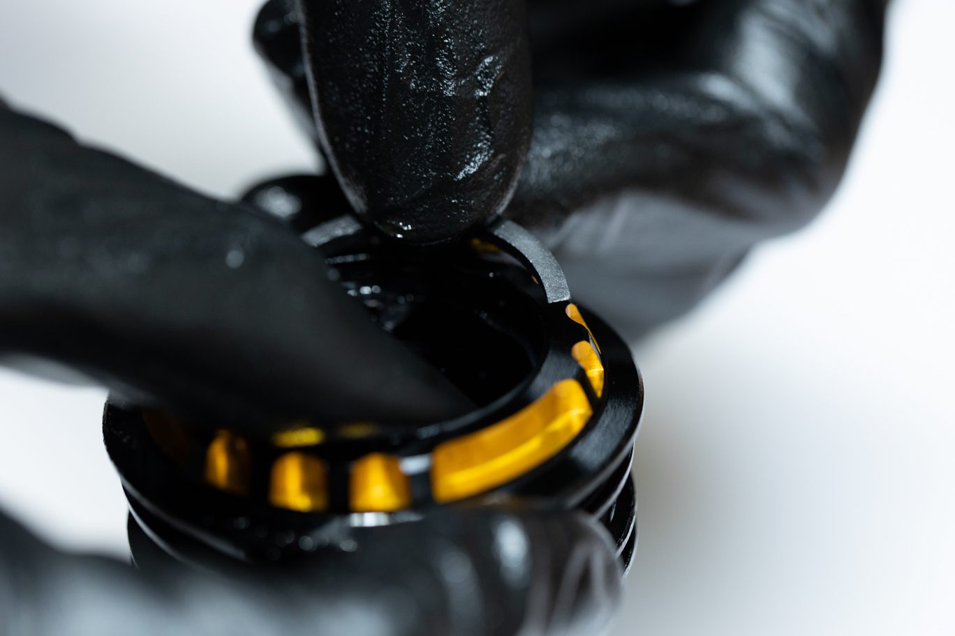
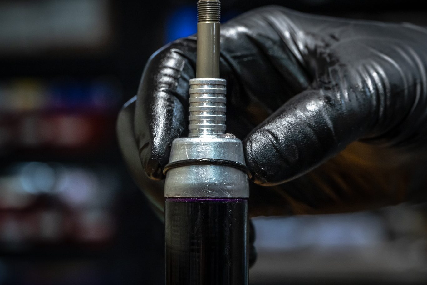
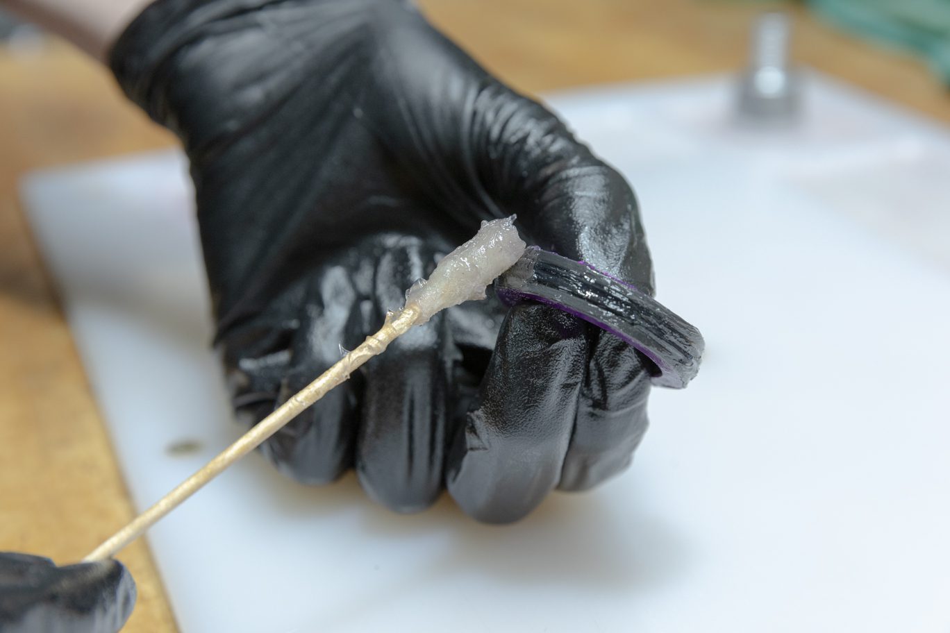
Grease the bushing and quad ring of oil seal head. If available, slide shaft cover (.DBT010 – discontinued) on shaft to cover threads only. Trim shaft cover to length if necessary. If cover not available, you can use tape to cover threads or simply take care installing seal head. Install new (AAD1090) top out bumper and new oil seal head (AAD1804). Remove any shaft thread covering.
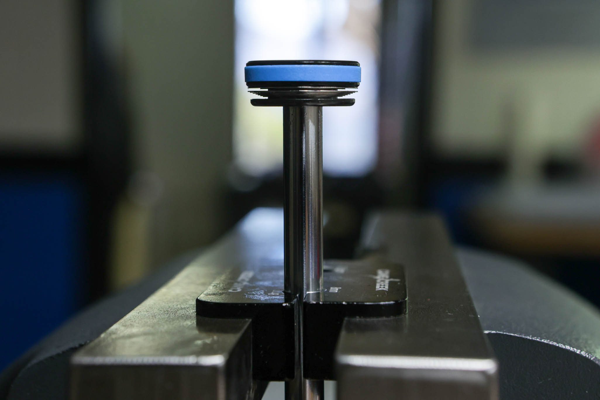
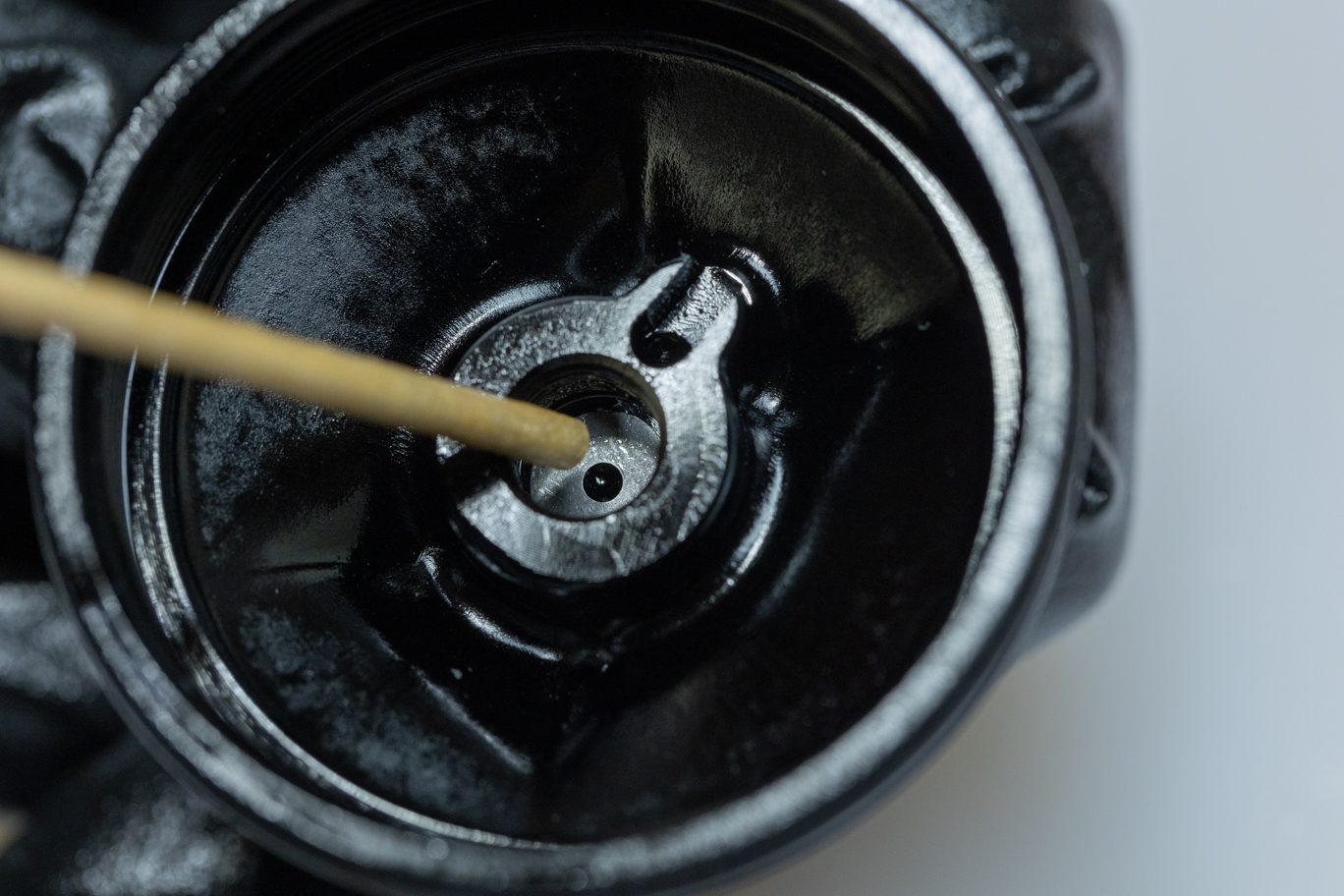
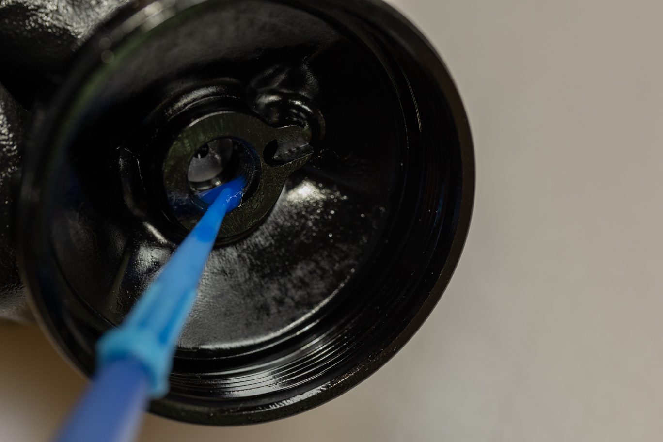
Apply a small amount of grease on the Compression (laser etched dot) needle hole and reinstall spring and detent balls (ball-spring-ball). Press then thread Compression needle into spool valve until flush. Confirm presence of detent clicks at this point.
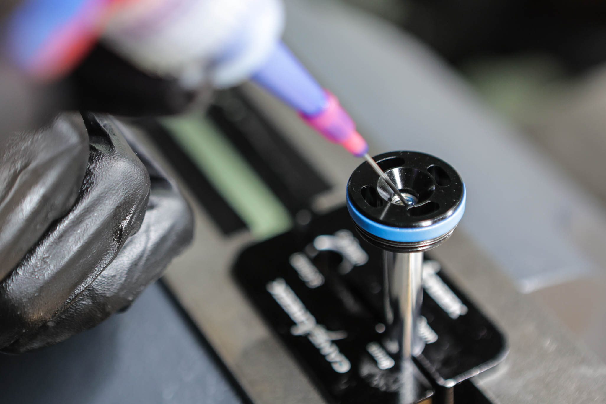
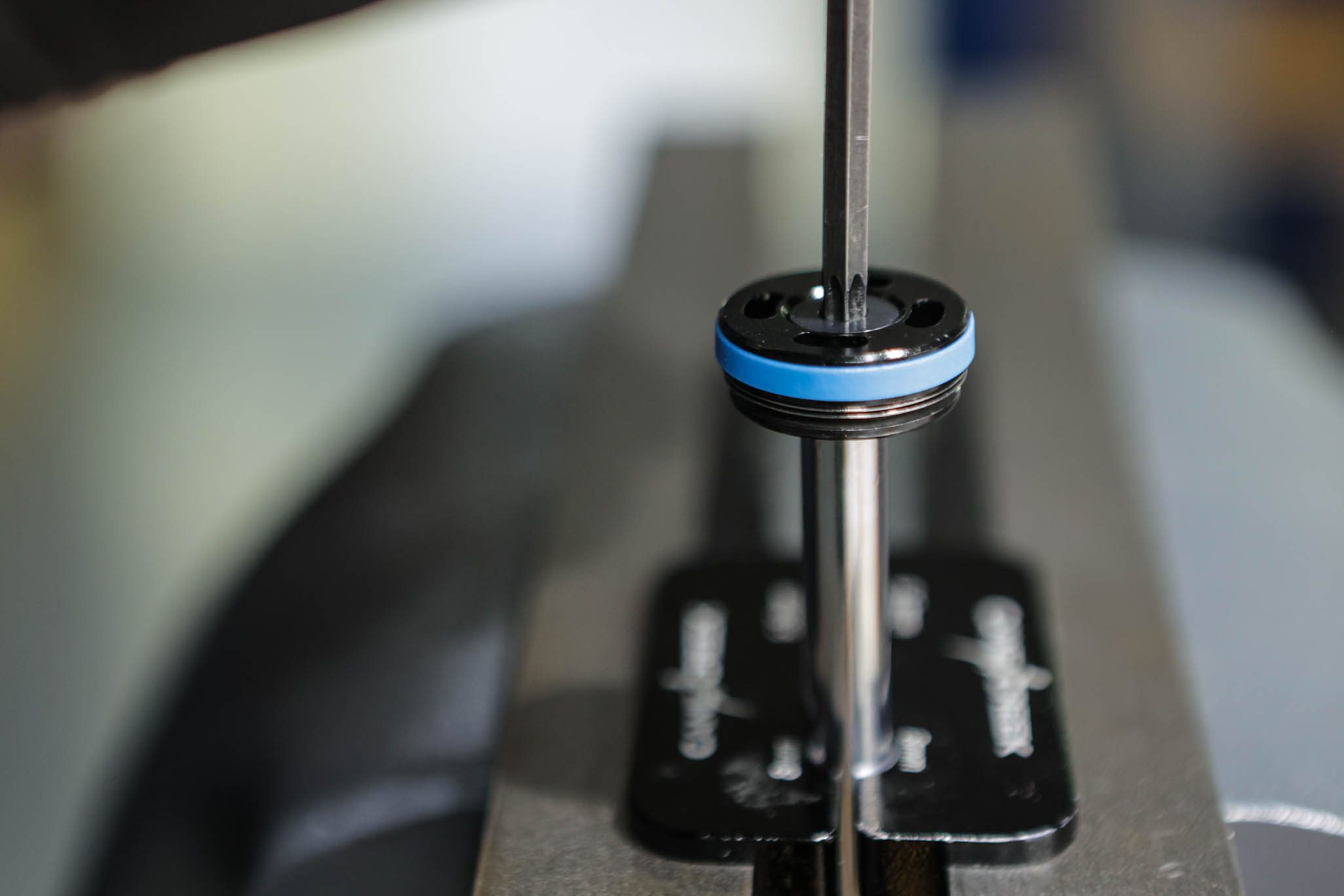
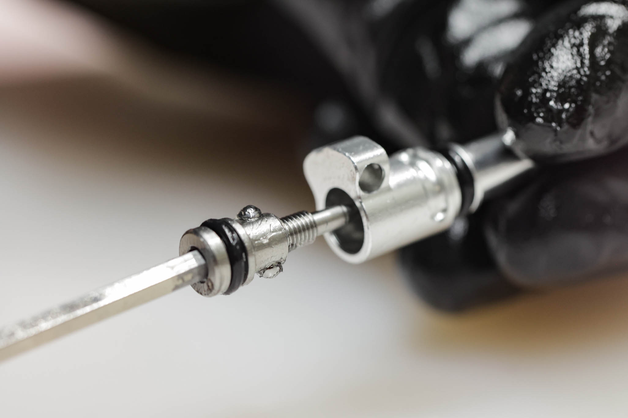
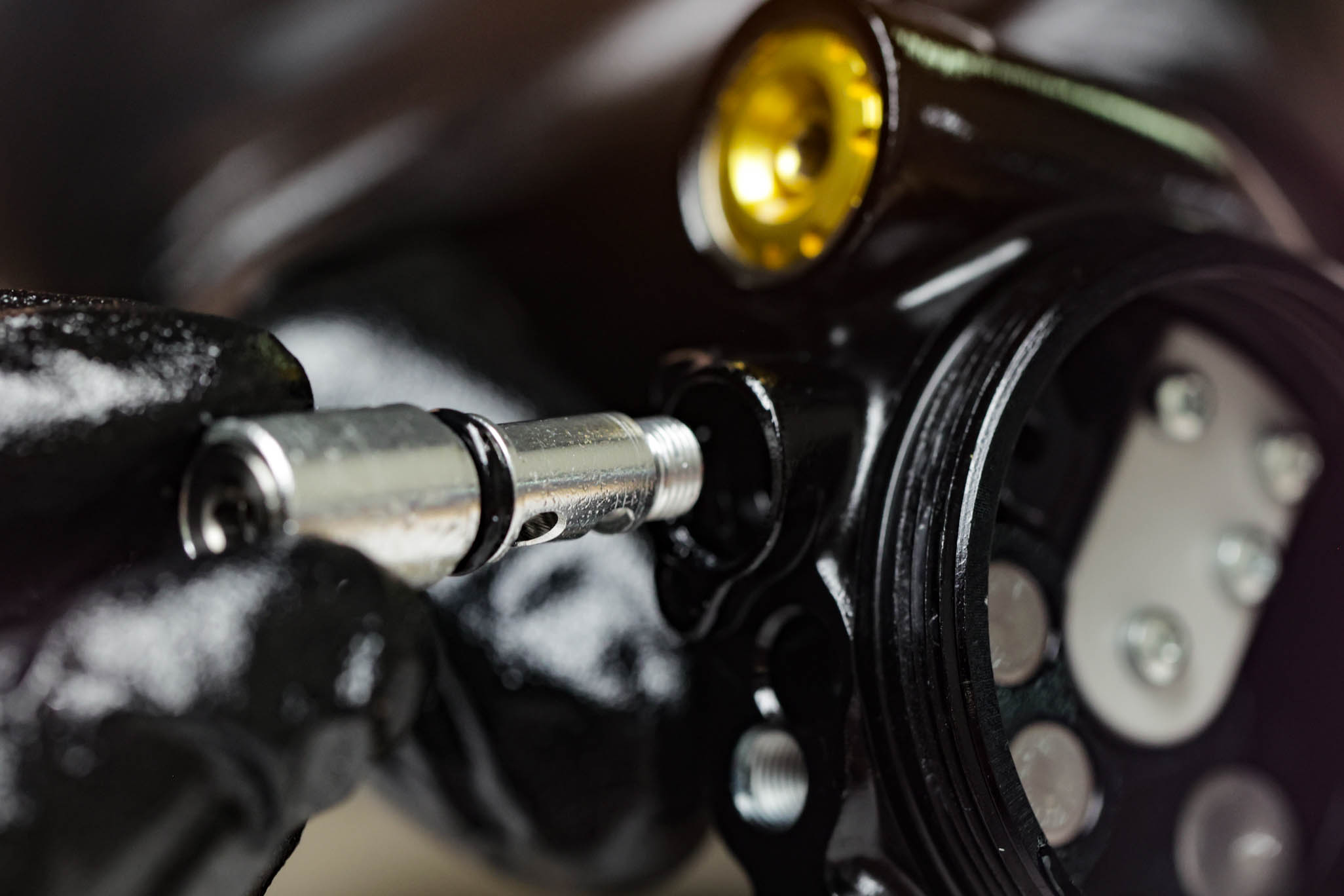
Thread spool valve into Low Speed Compression on valve body. Thread until full bottom out. Install detent plunger and spring. Depress detent plunger and back out spool valve half to one and a half turns to capture detent in track. Ensure spool valve can fully reach both open and closed positions. Reinstall capture screw on spool valve with blue Loctite (243). Torque to .16 Nm with 1.5mm Allen.
Apply a small amount of grease on the Rebound (no laser etching) needle hole and reinstall spring and detent balls (ball-spring-ball). Press then thread Rebound needle into Low Speed Rebound on valve body. Thread past circlip shelf. Confirm presence of detent clicks at this point. Install circlip into groove. Back needle out gently to ensure proper seatment of circlip.
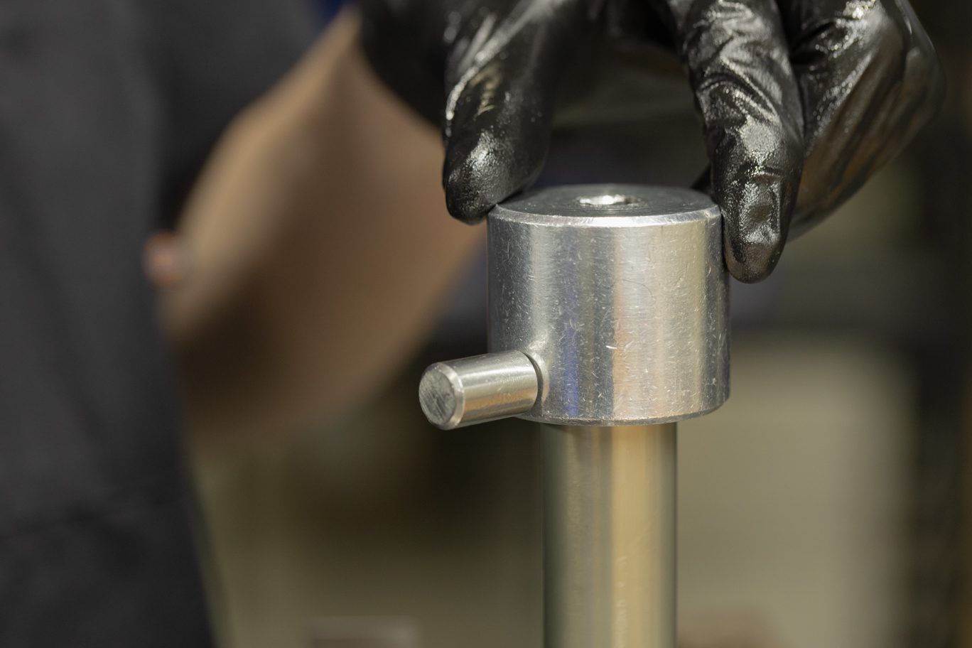
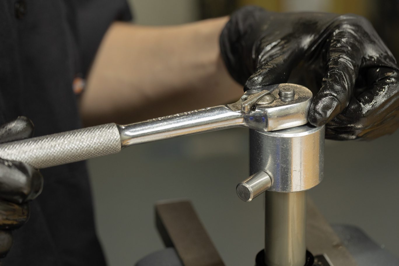
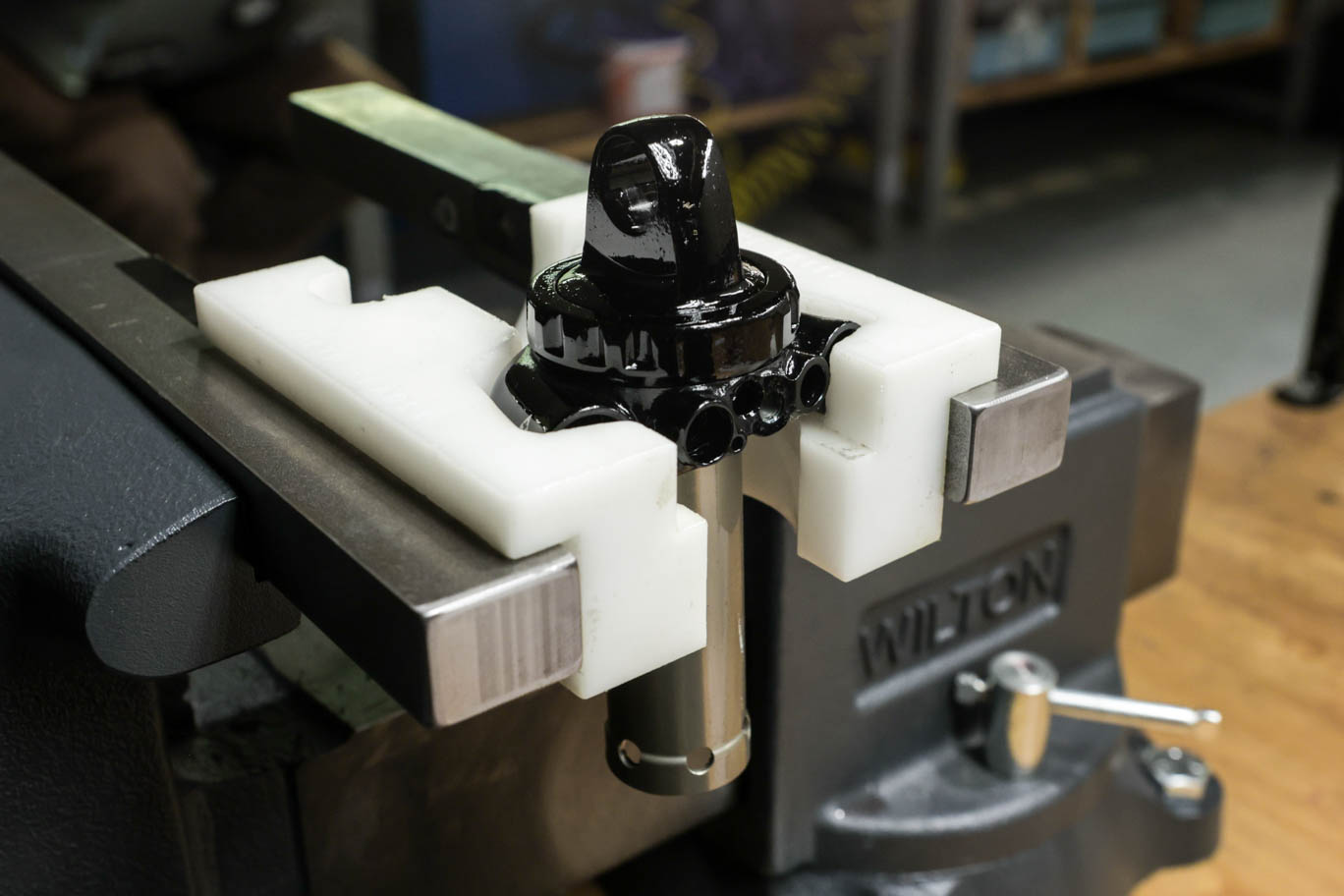
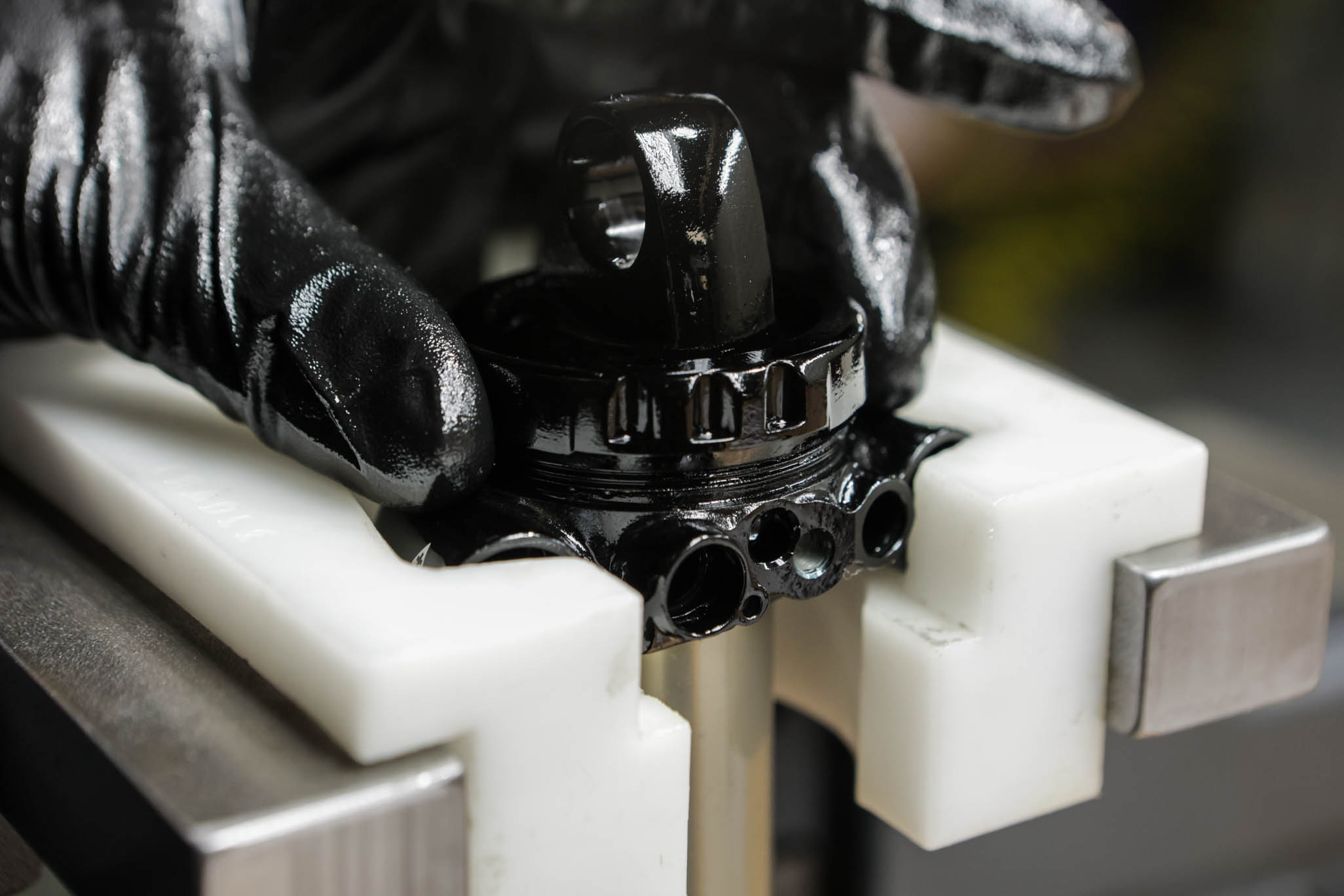
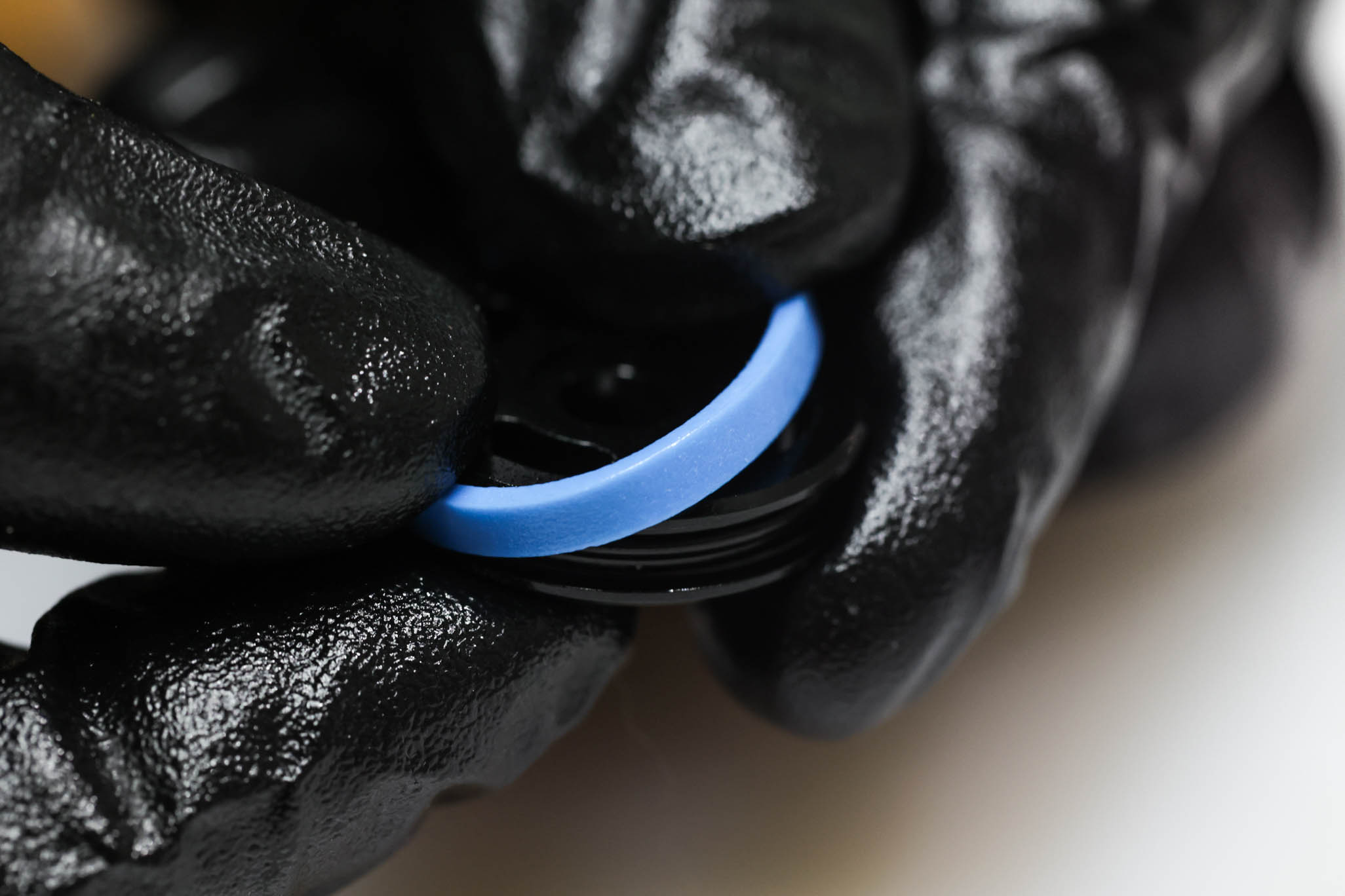
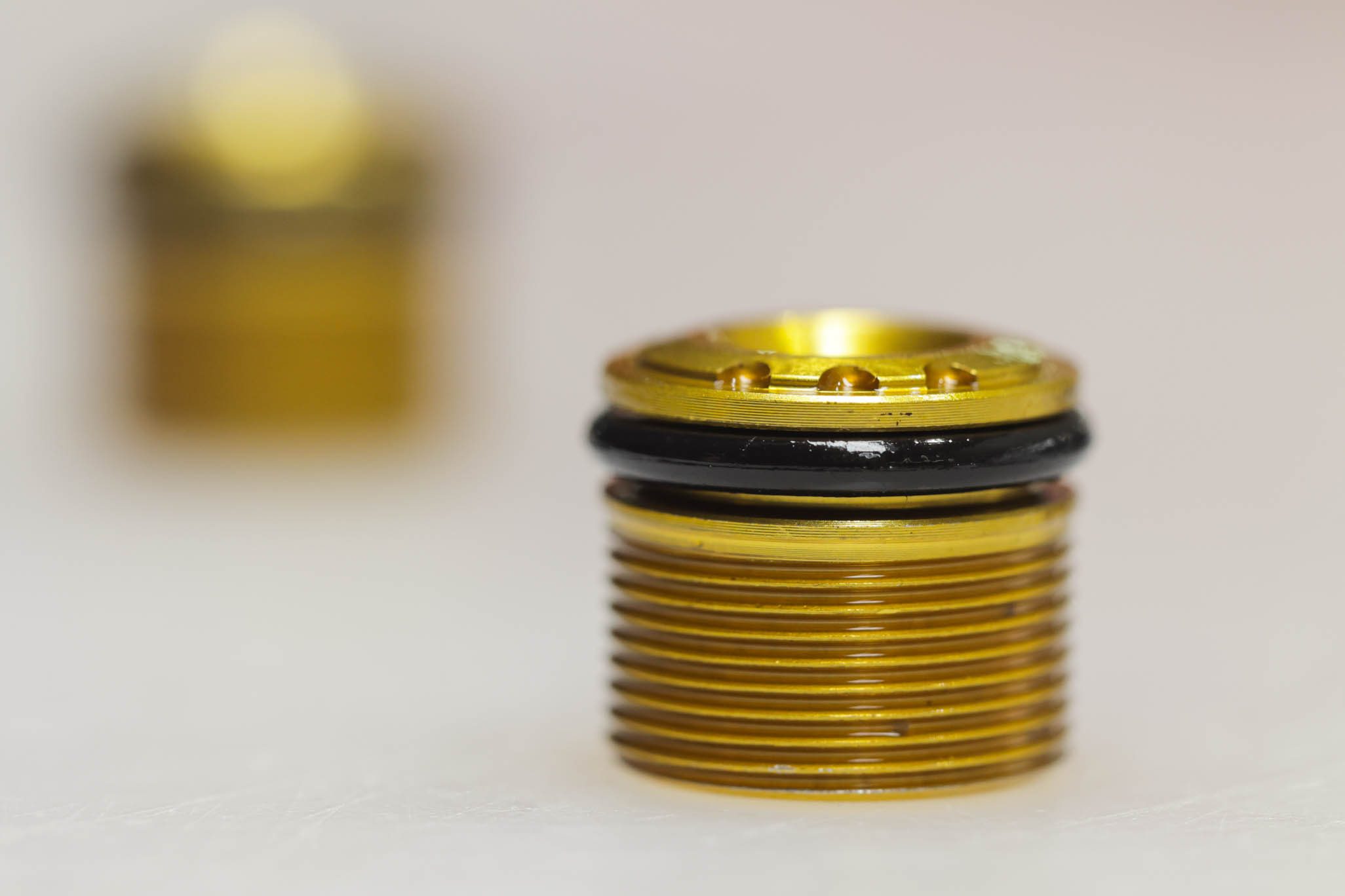
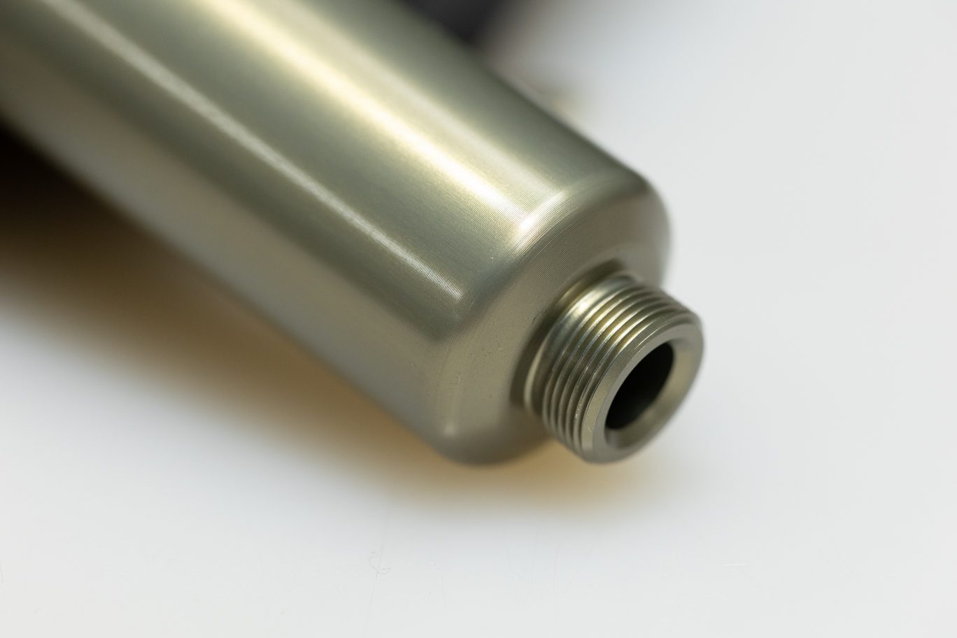
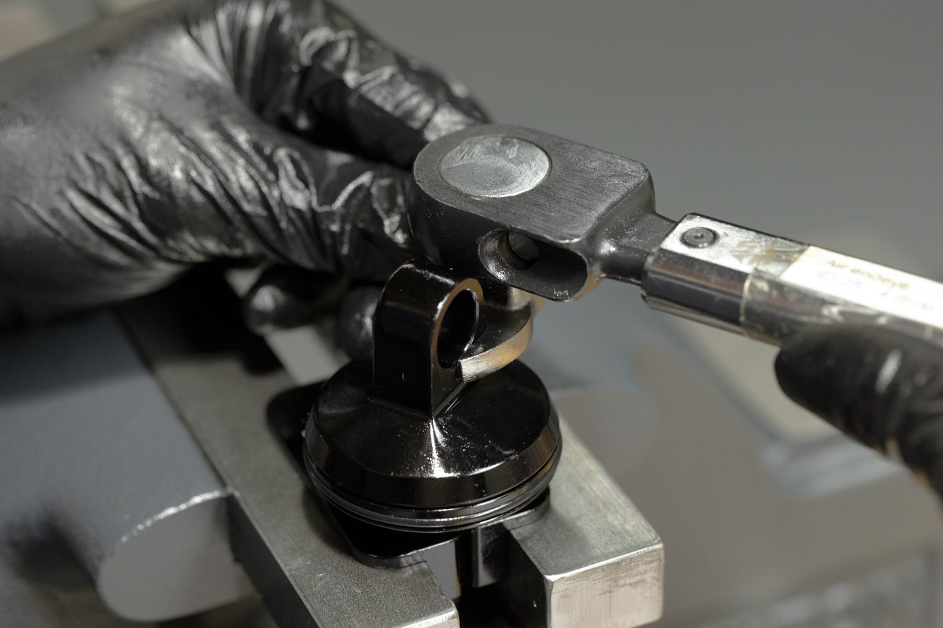
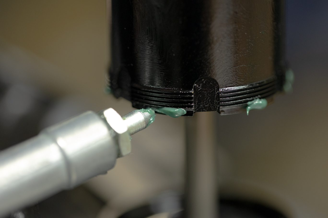
Lightly grease and install o-ring (AAD0955) on valve body. Ensure o-ring is fully seated in groove. Clamp valve body end eye in vise. Ensure all old Loctite is removed from inner damper tube. Apply fresh red Loctite (263) to threads. Thread inner damper tube into valve body. Using inner damper tube wrench, torque to 17 Nm.
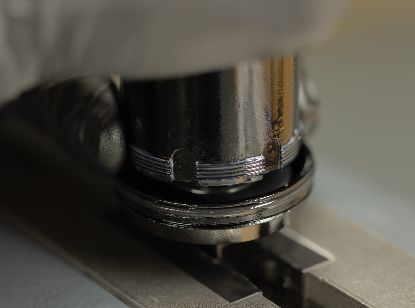
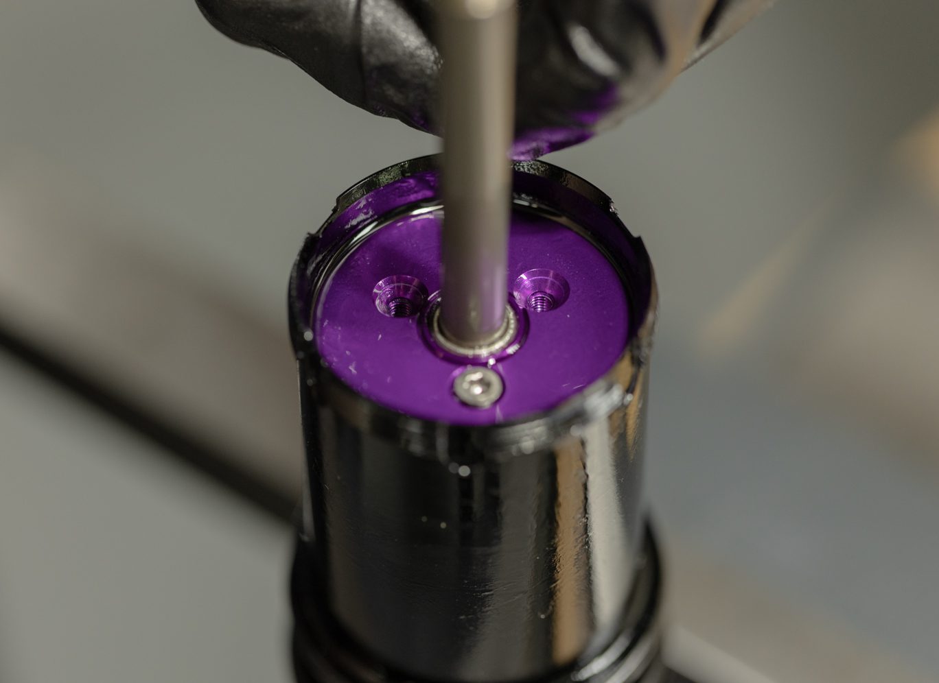
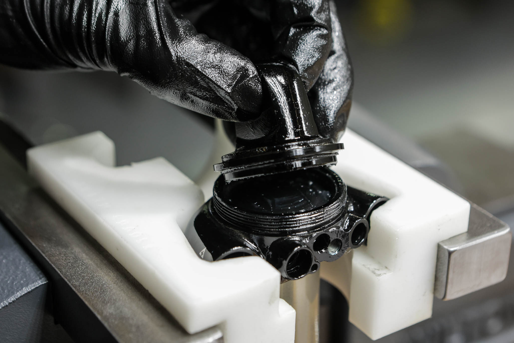
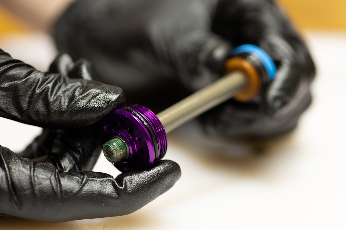
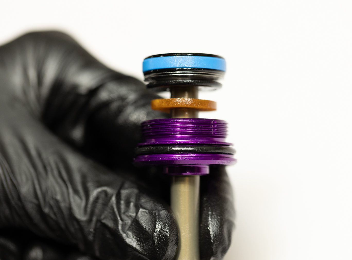
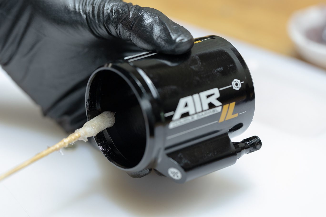
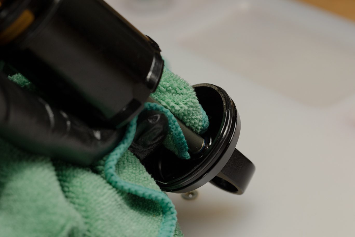
If not already installed, lightly grease and install o-ring (AAD0955) on valve body. Ensure o-ring is fully seated in groove. Set valve body in Keith Cradle or clamp end eye. Apply thin layer of shock oil to outer damper tube on the external chamfer end. Press and rotate outer damper tube into valve body until seated on o-ring.
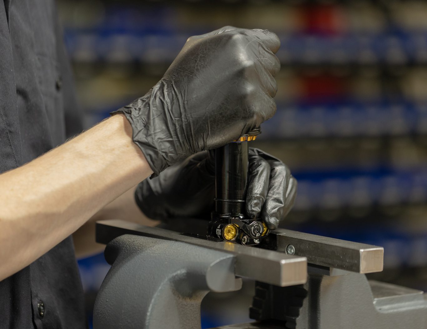
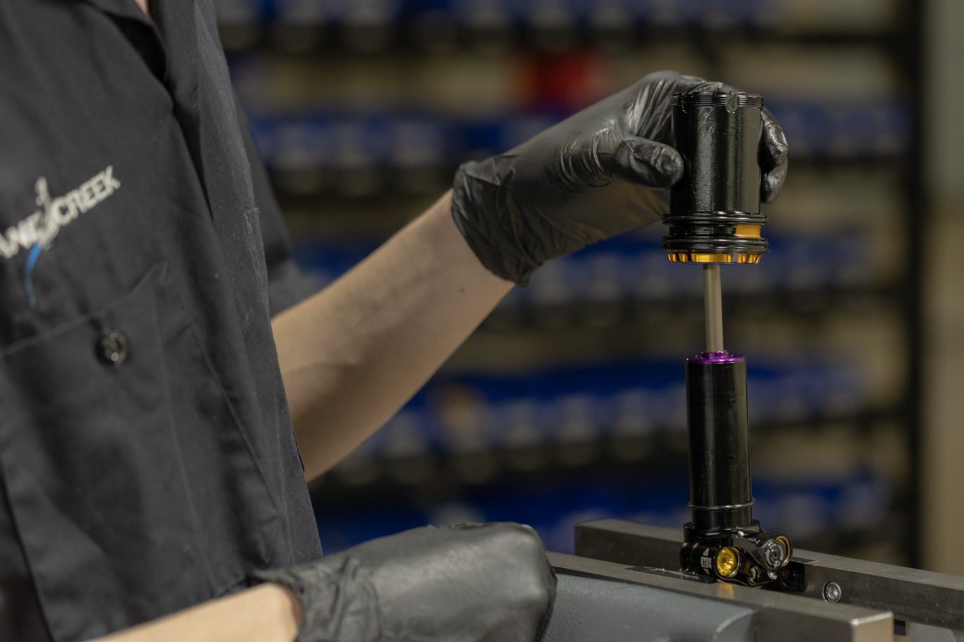
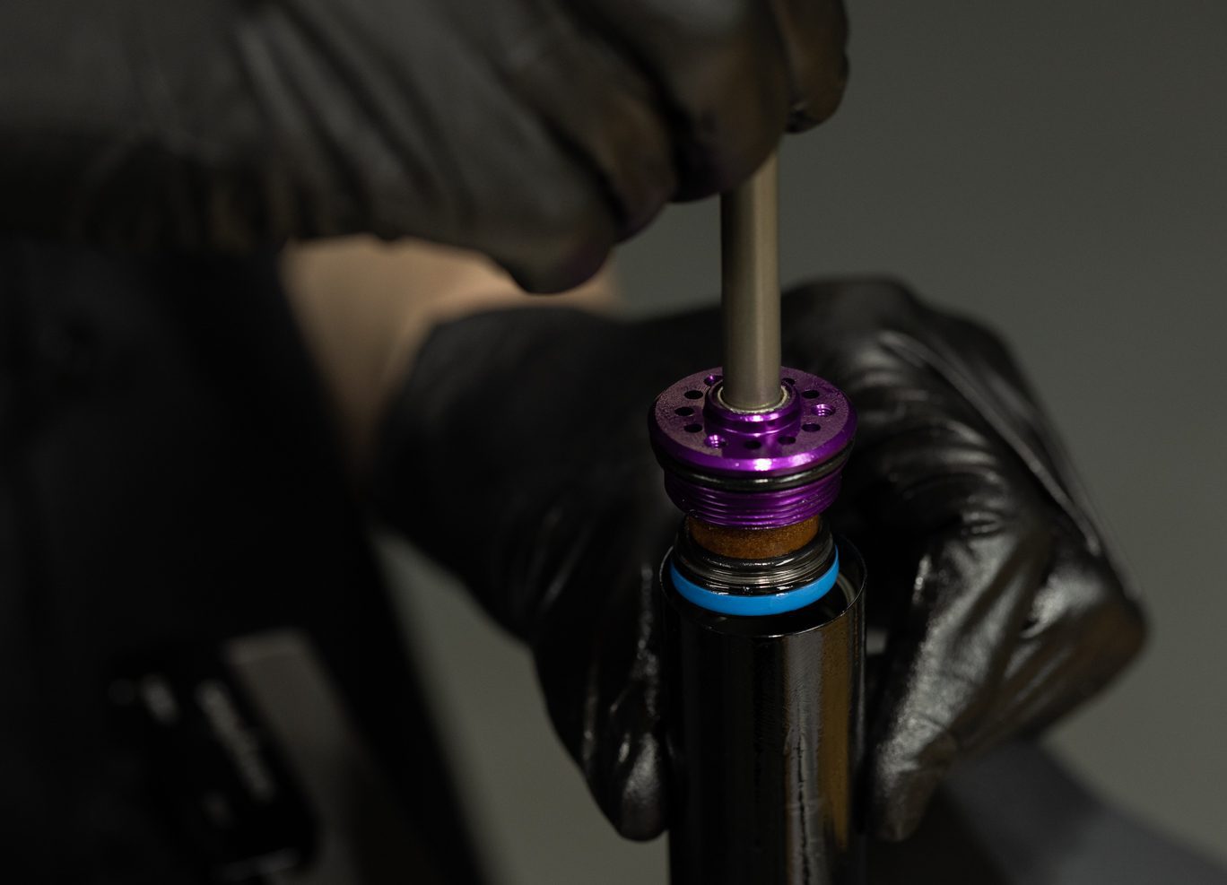
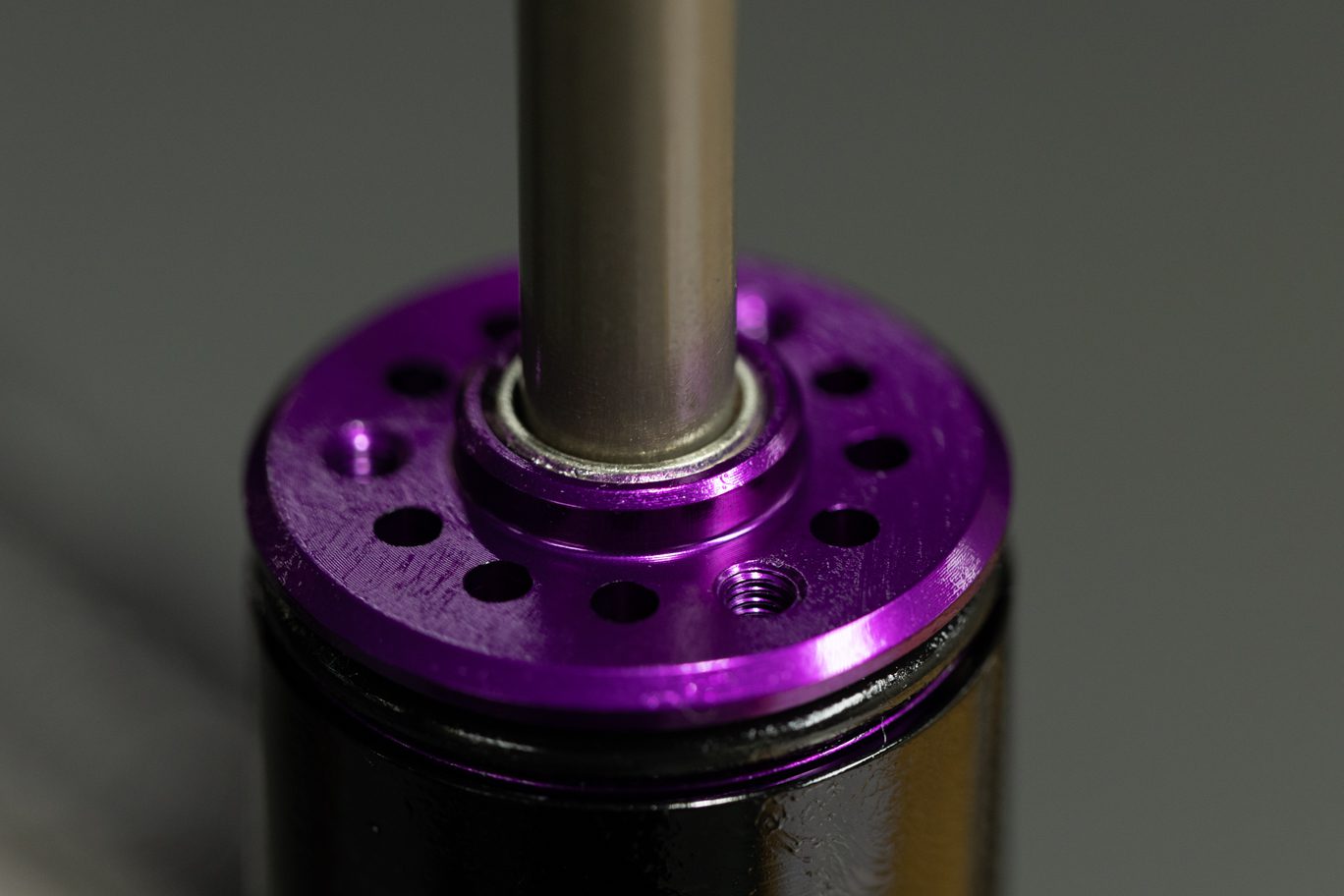
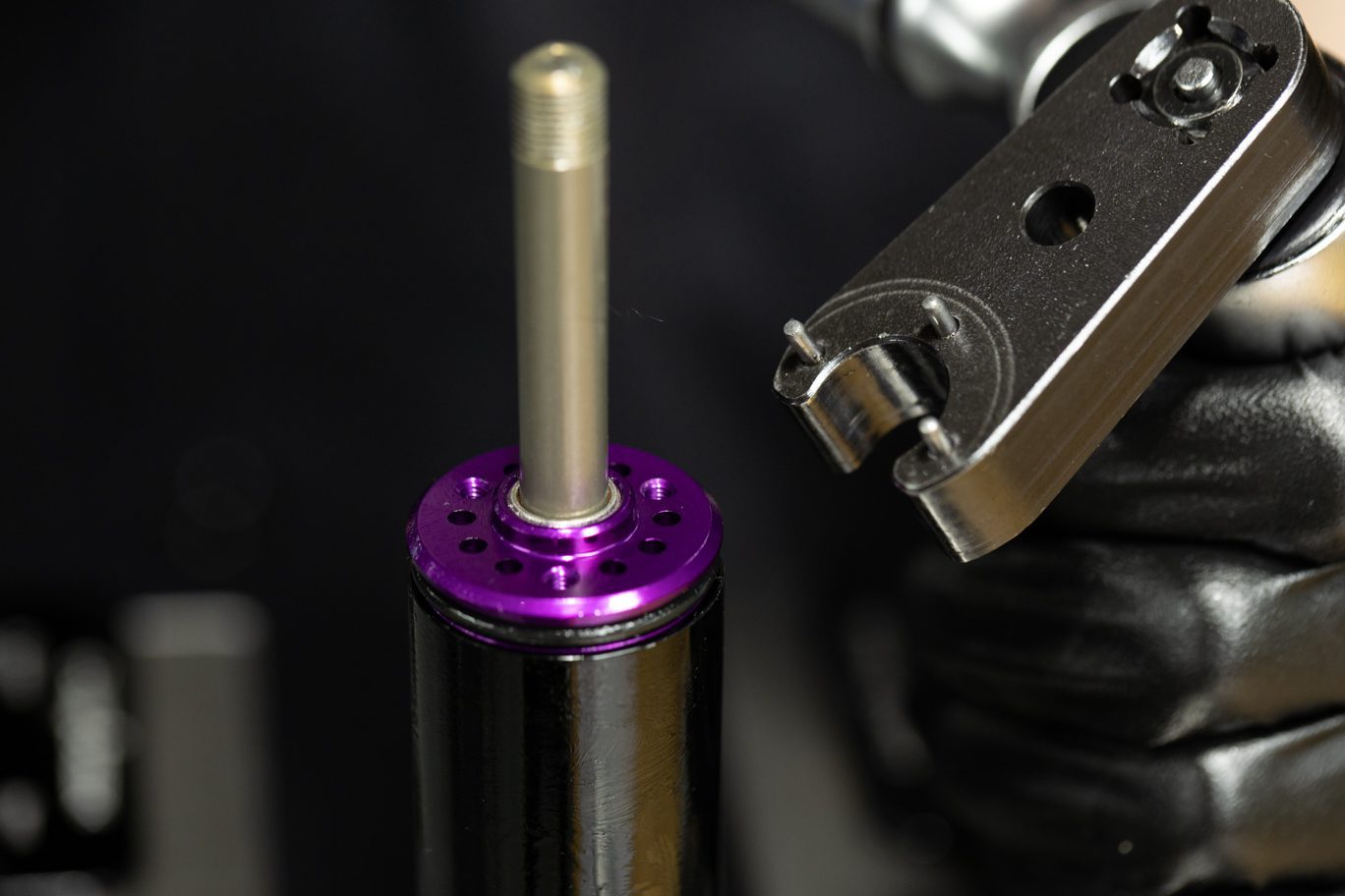
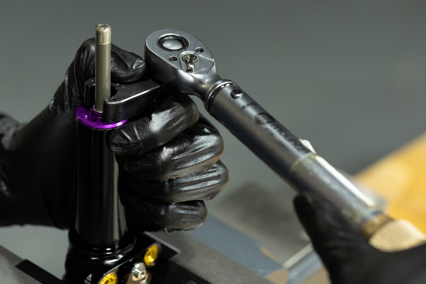
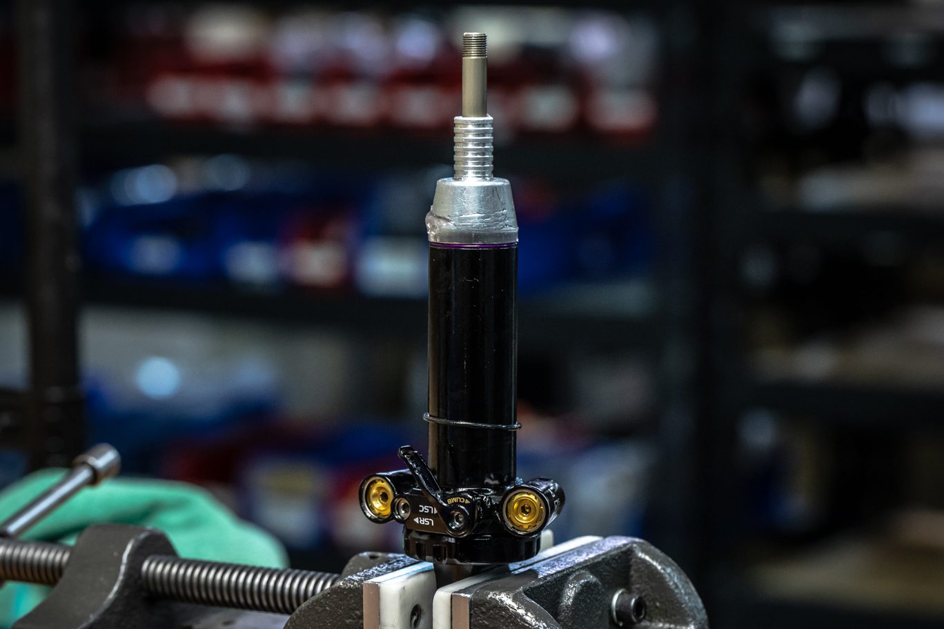
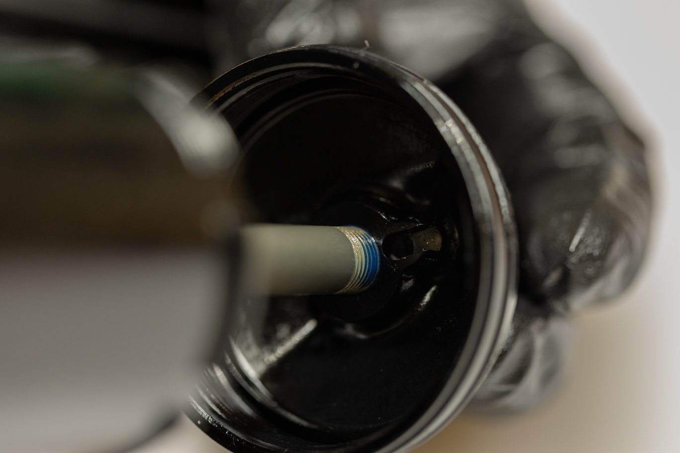
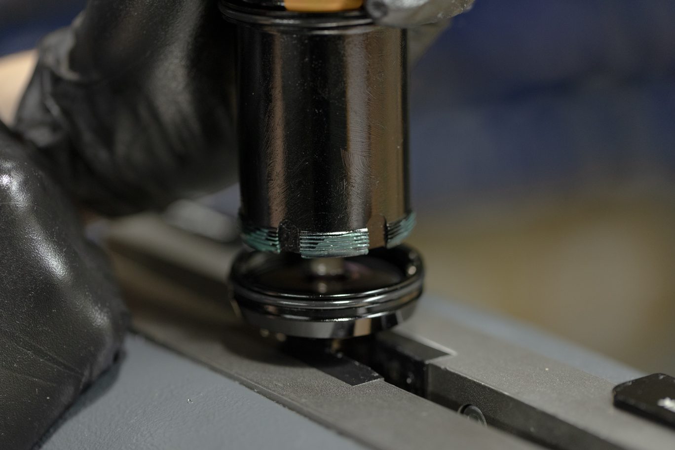
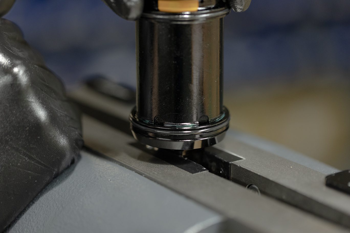
Apply thin layer of shock oil to piston band on shaft assembly. Use piston to apply layer of shock oil to inner surface of outer damper tube. Insert shaft assembly into inner damper tube, threading oil seal head into outer damper tube. Using Oil Seal Head Wrench, tighten oil seal head to 15 Nm.
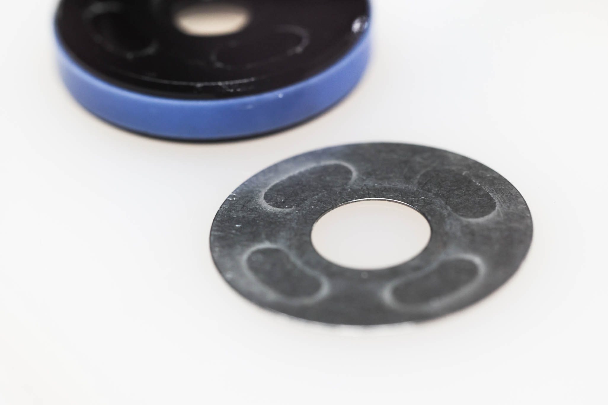
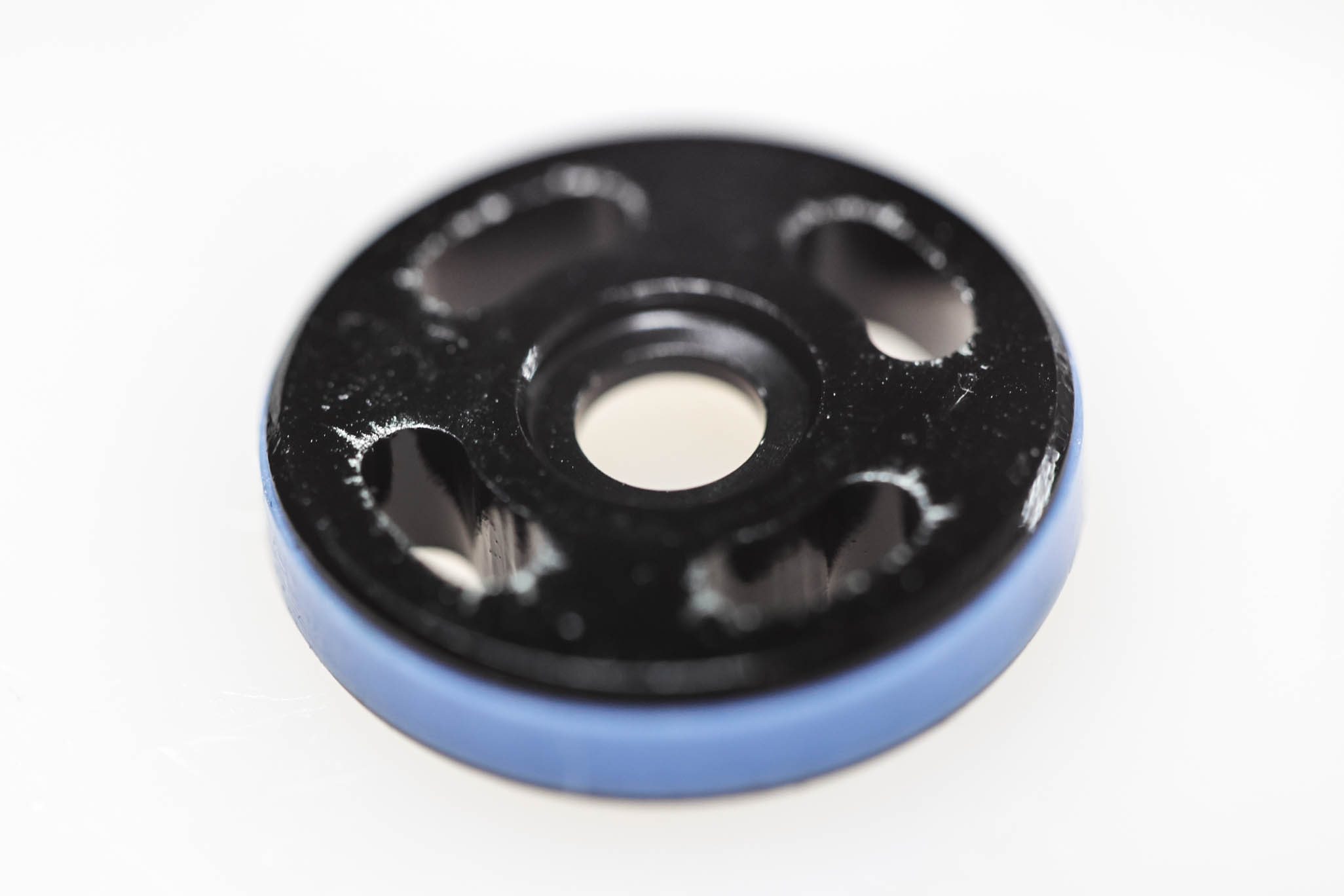
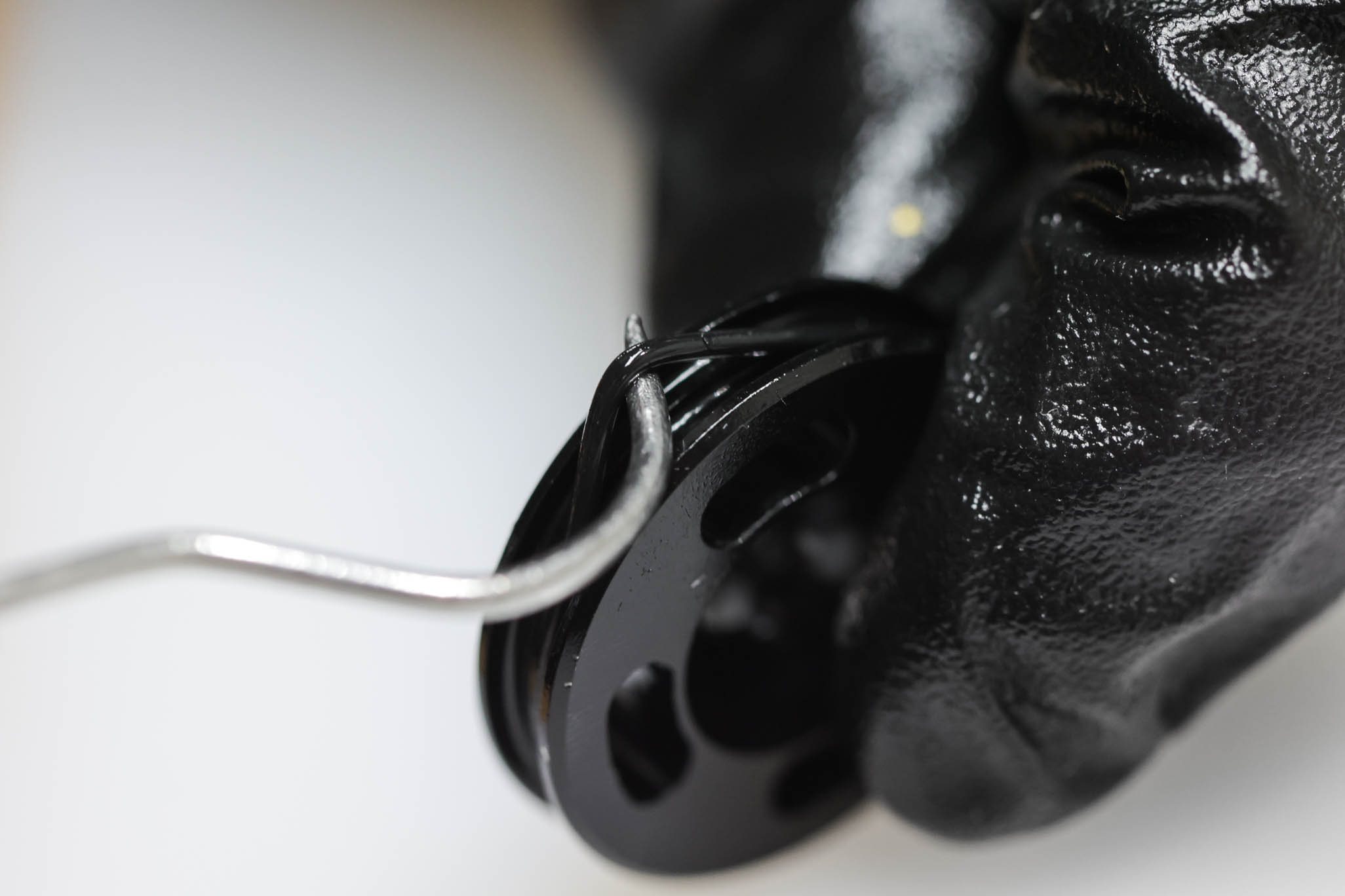
Use non-threaded holes and ensure all three pins are properly seated and even pressure is applied to tool to prevent damaging tool pins.
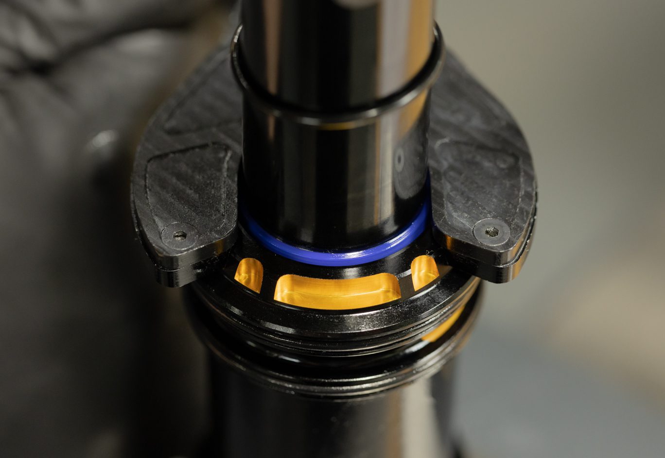
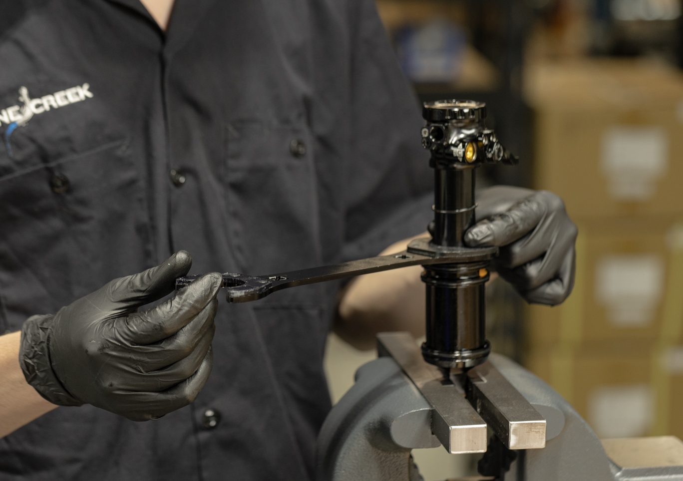
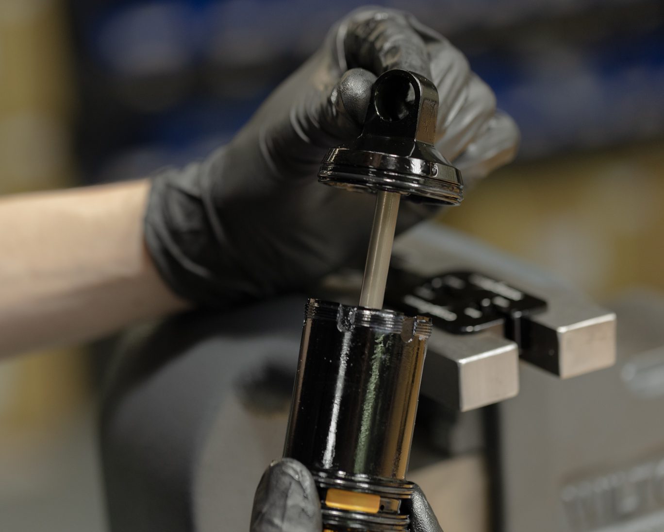
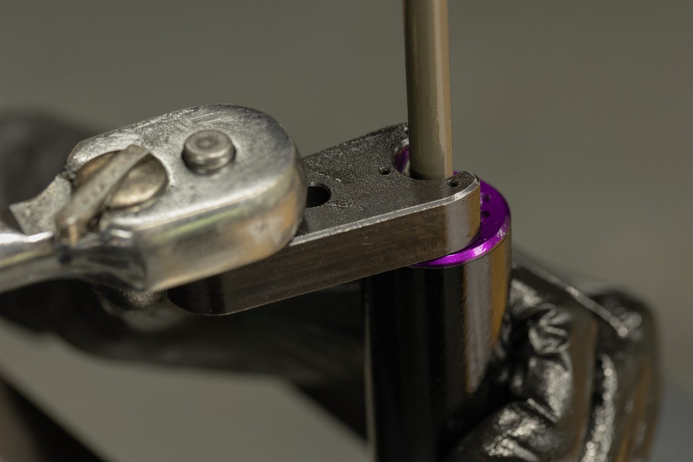
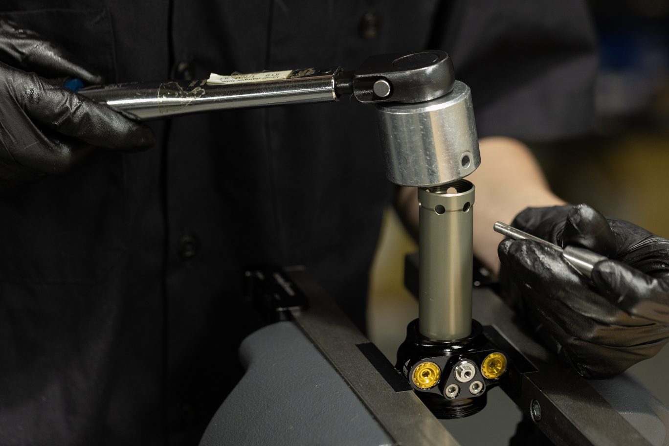
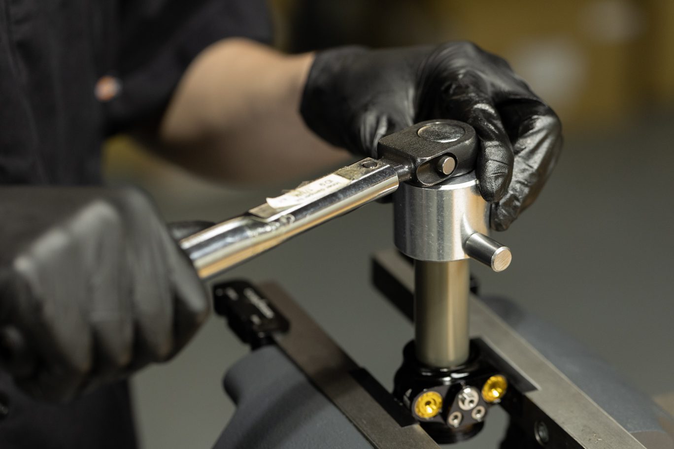
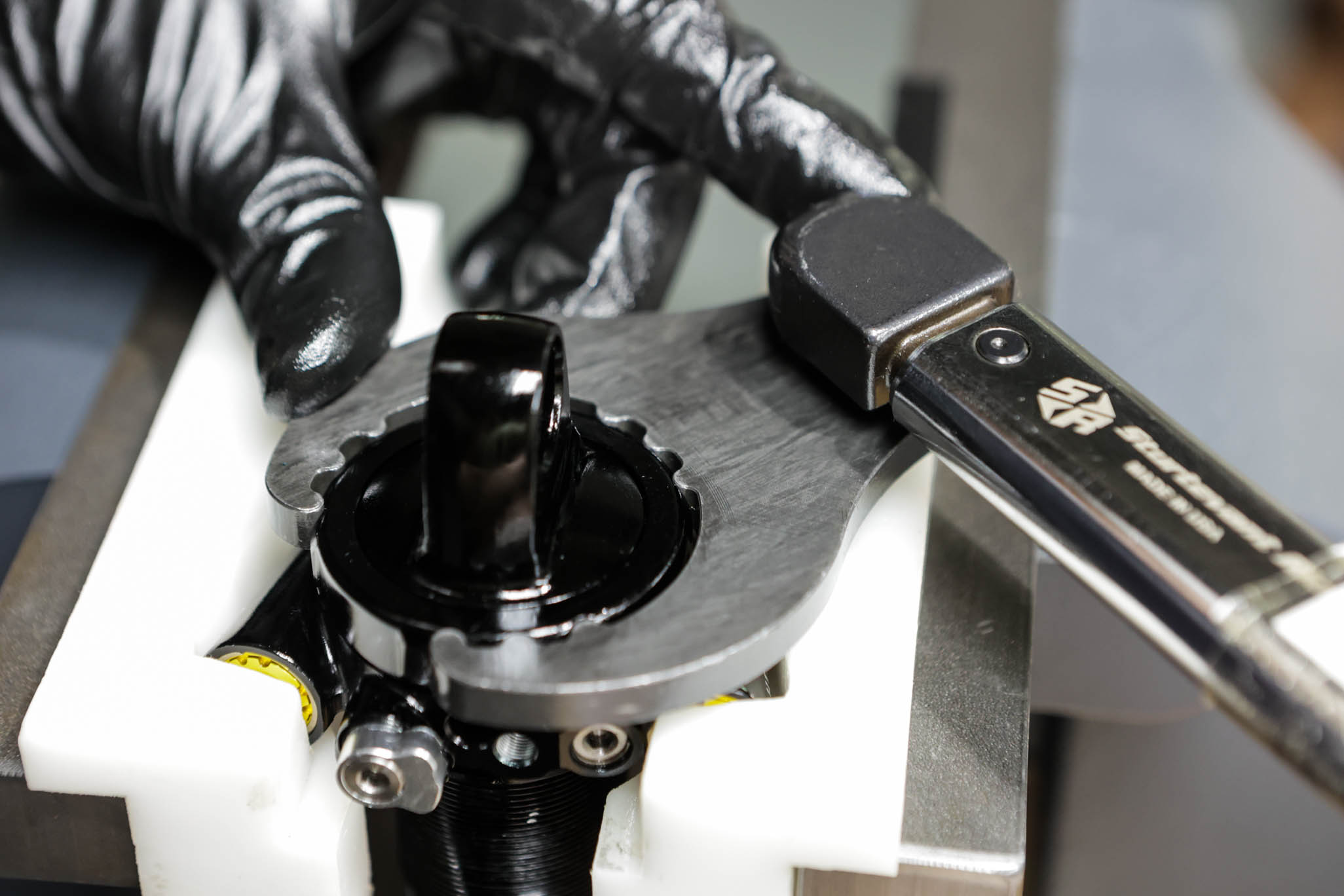
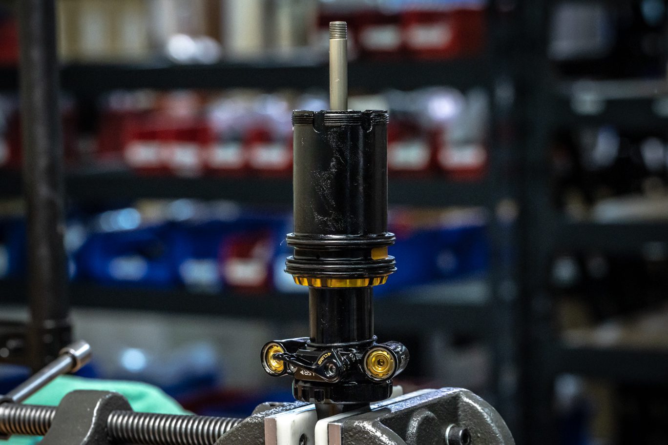
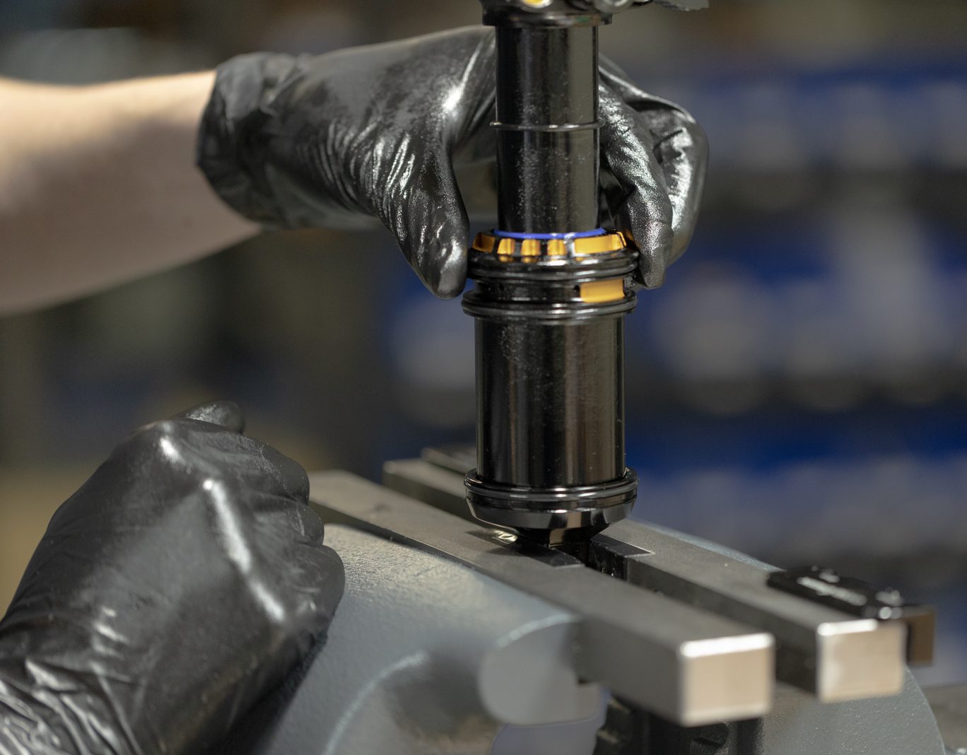
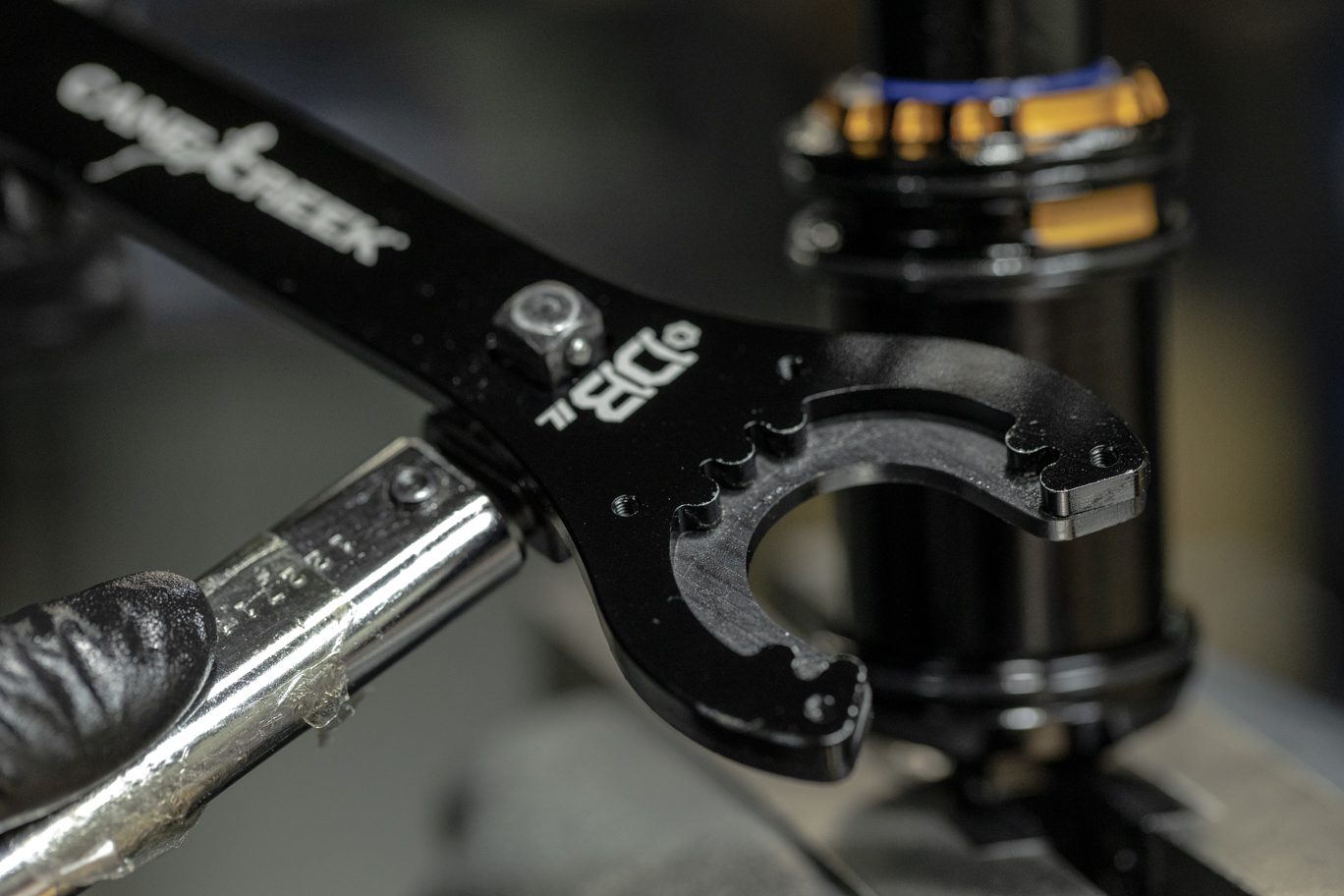
Place upper end eye on bladder. Do not push end eye onto valve body as it can unseat the bladder. Install gland nut using an inch feed of blue Loctite (243). Set correct end eye orientation and allow gland nut to self seat the end eye. Using Gland Nut Wrench and Keith Cradle torque gland nut to 52 Nm.
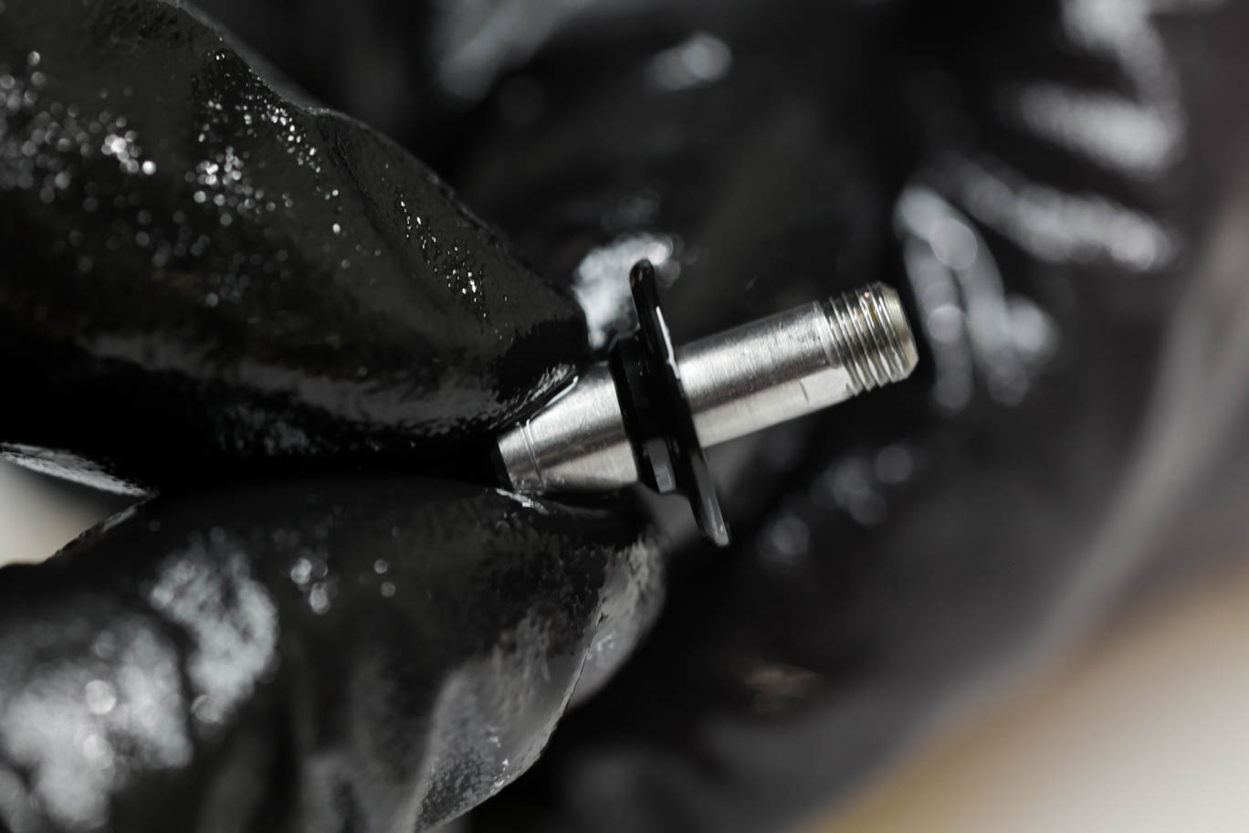
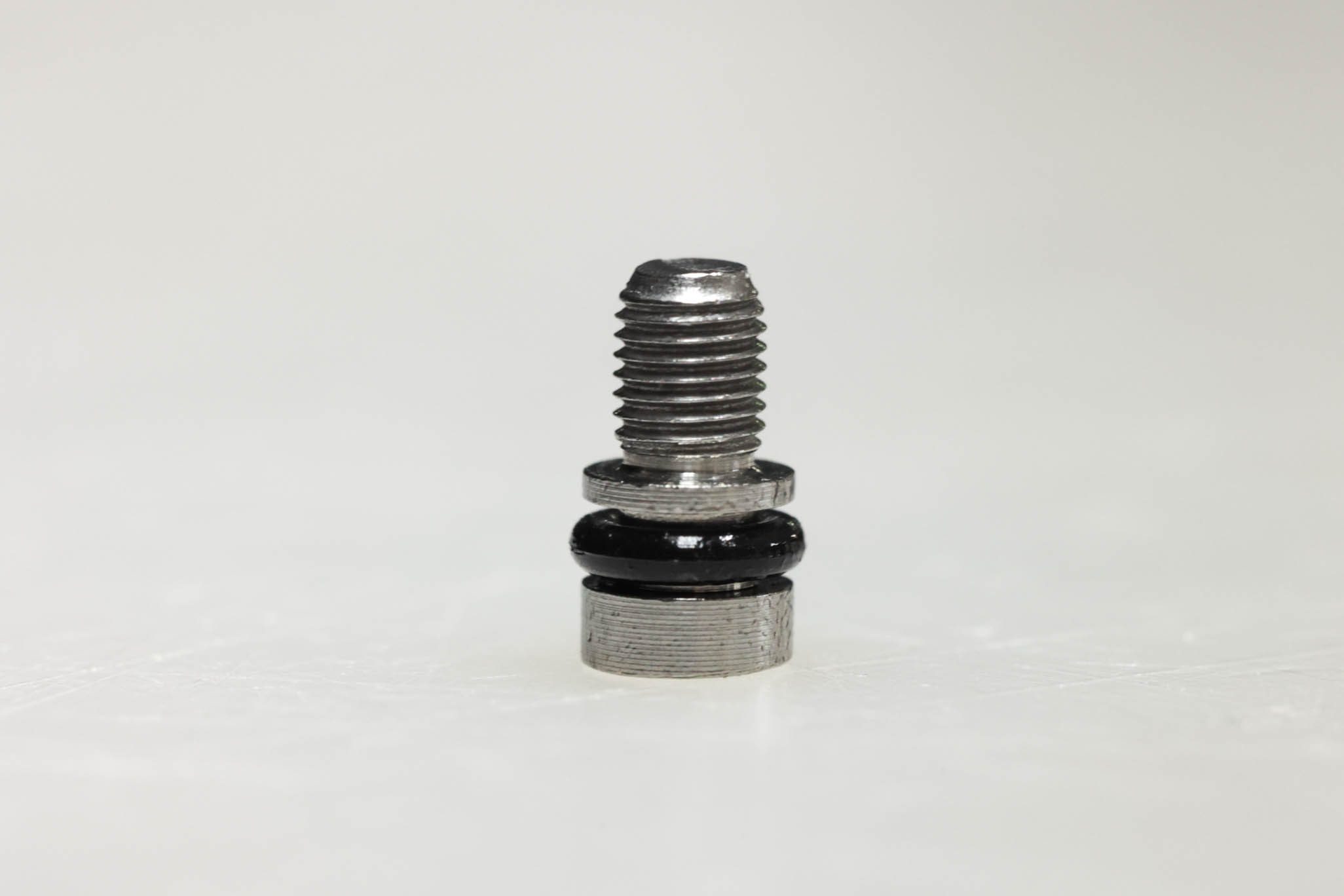
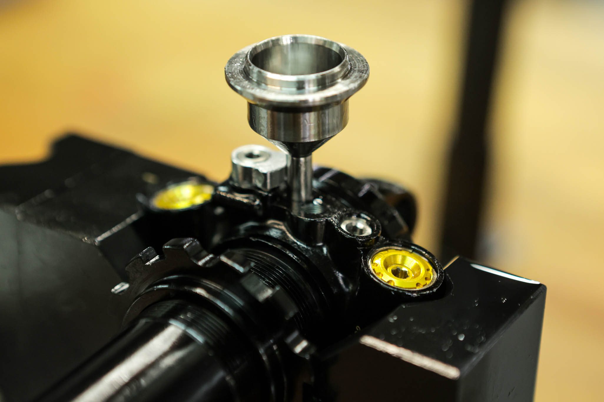
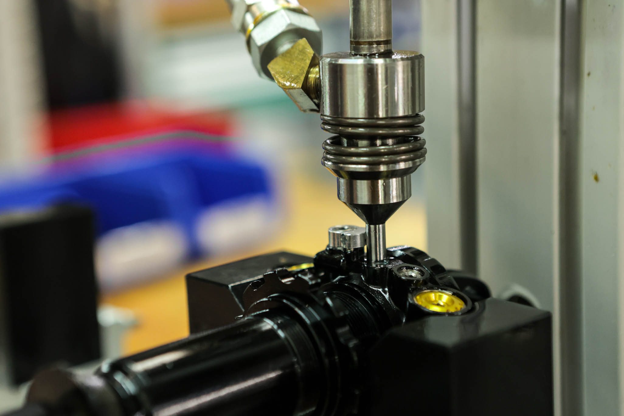
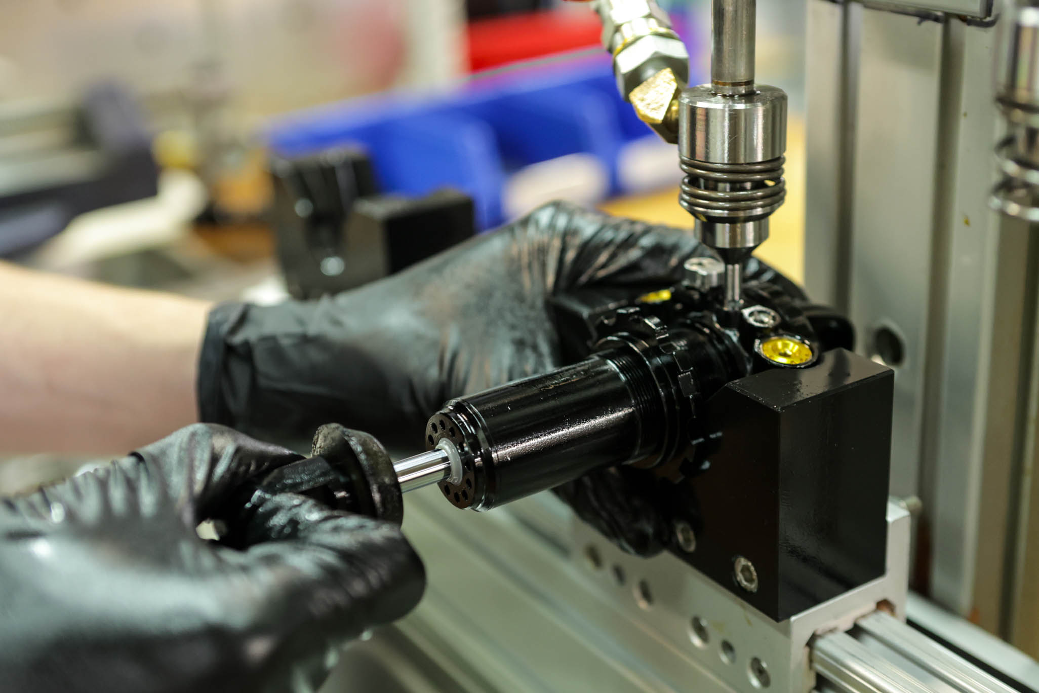
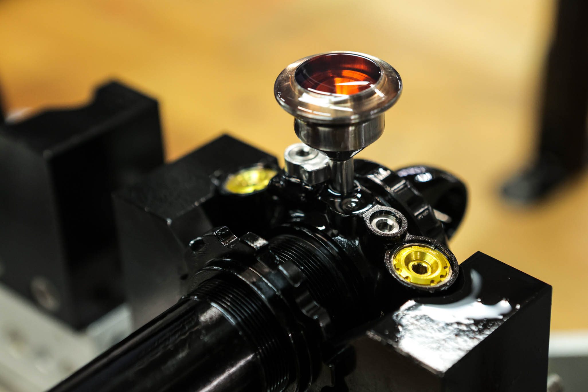
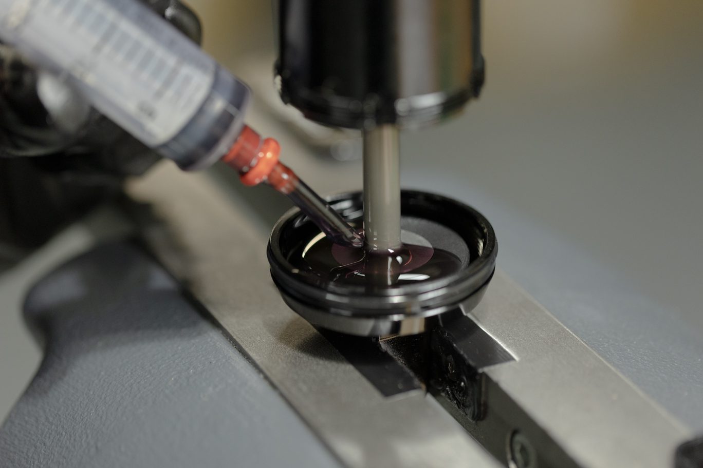
Install new o-ring (AAD0532) on fill plug screw. Temporarily install end eye on shaft. Secure shock in horizontal position with fill port facing up. Back all adjusters to fully open and open Climb Switch. Thread Inline oil fill adaptor (BAD1268) into fill port. Fully compress damper. Attach oil fill machine per your manufacturer’s instructions.
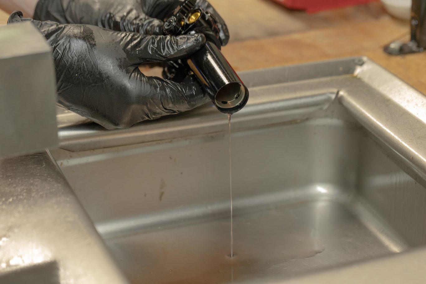
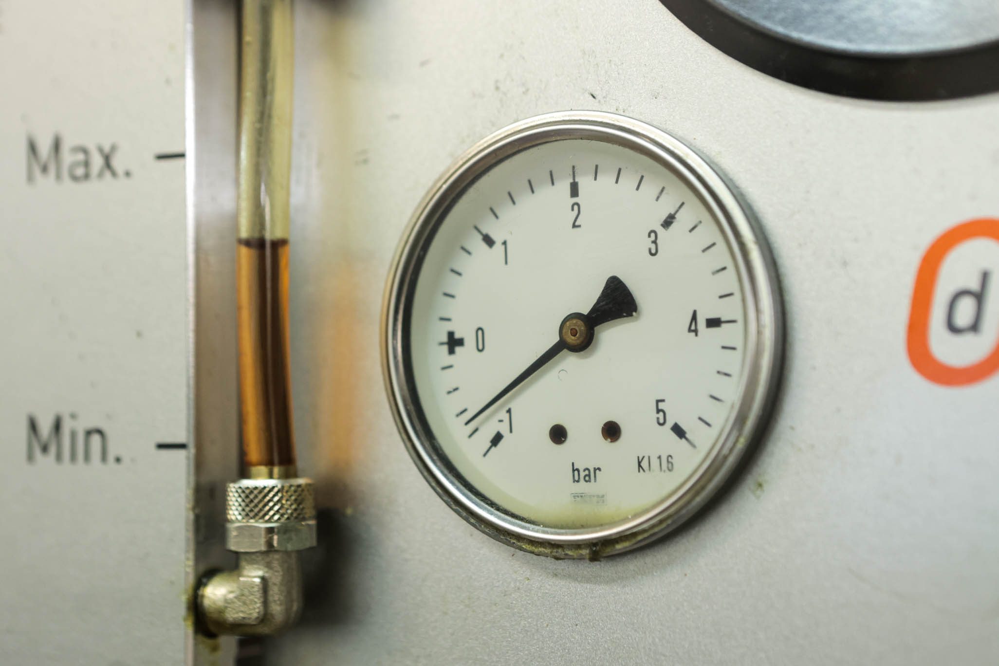
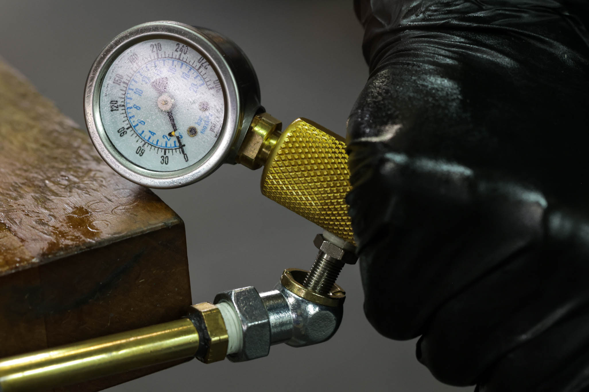
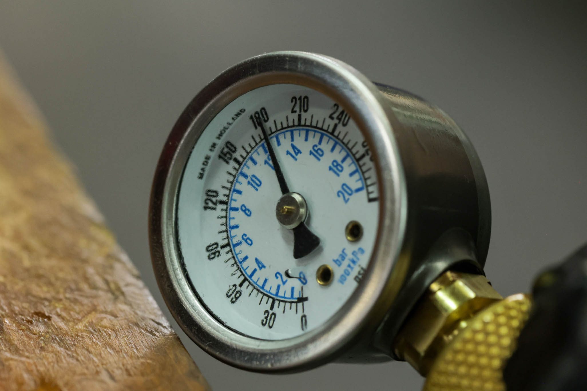
Vacuum system to (4) mbar. Pressure with Oil to (3) bar. Slowly cycle shaft finishing with shaft fully out. Cut fill and equalize pressure. Vacuum system to (4) mbar, leaving shaft out. Pressure again with Oil to (3) bar. Slowly cycle shaft finishing with shaft fully out. Cut fill.
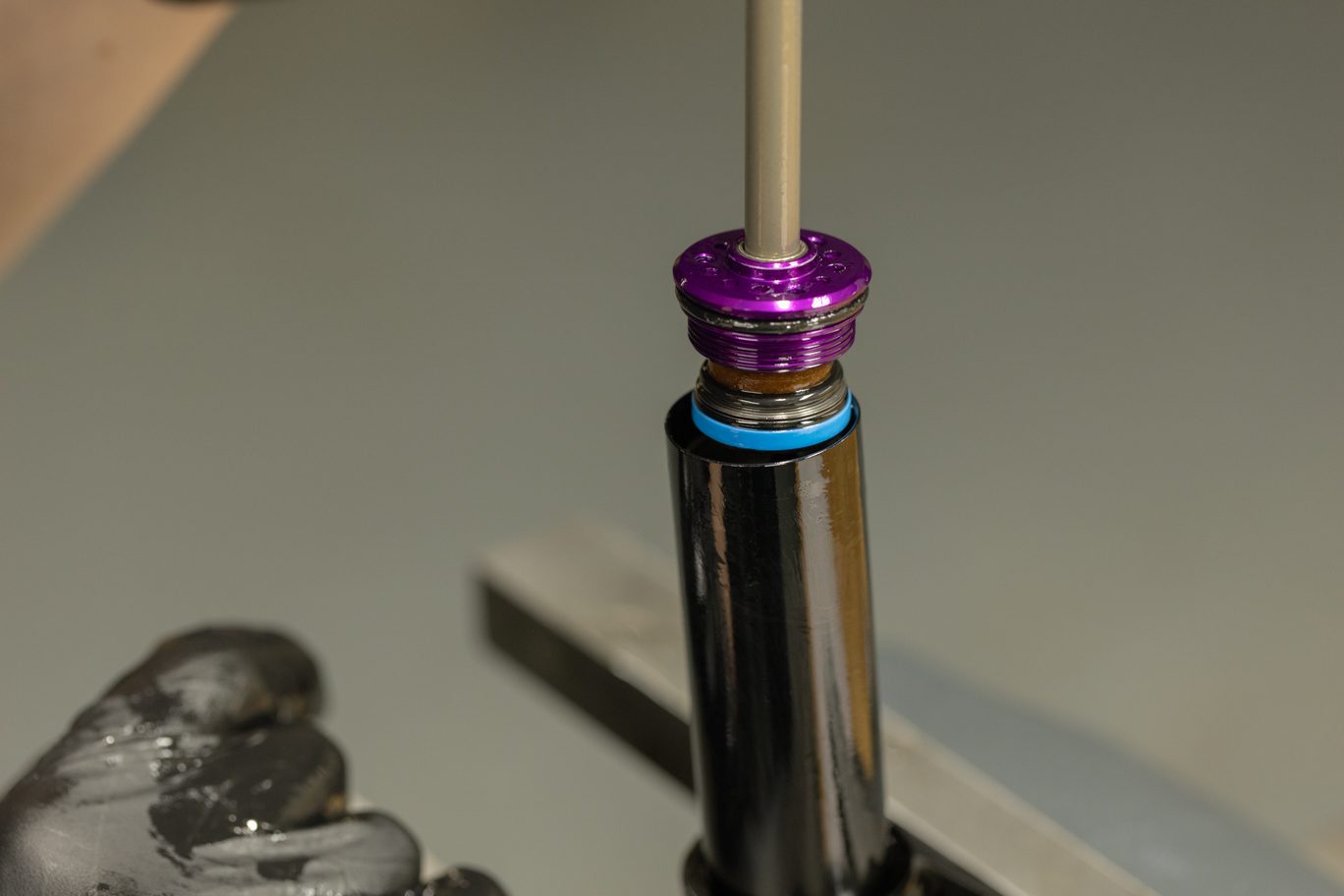
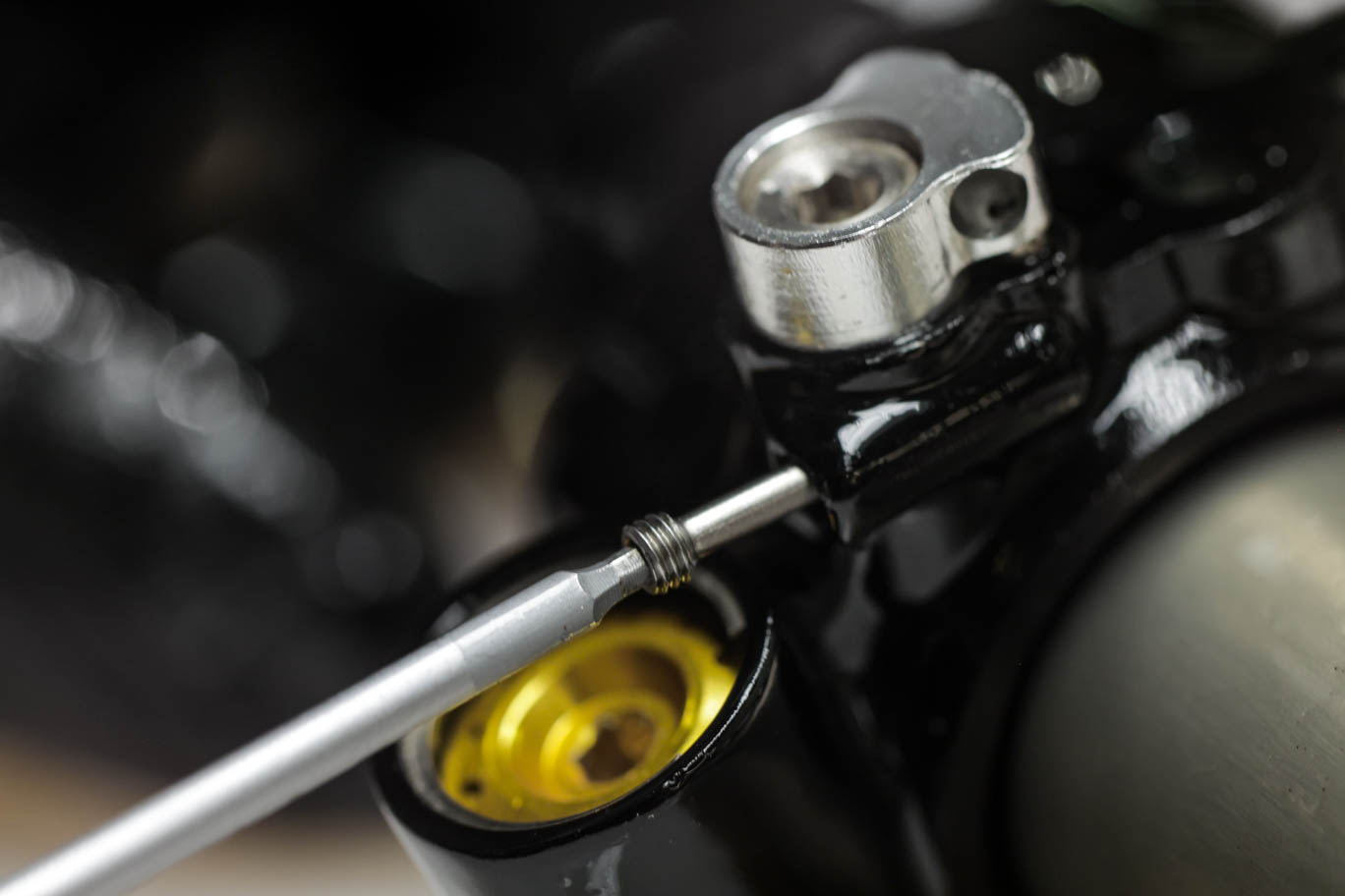
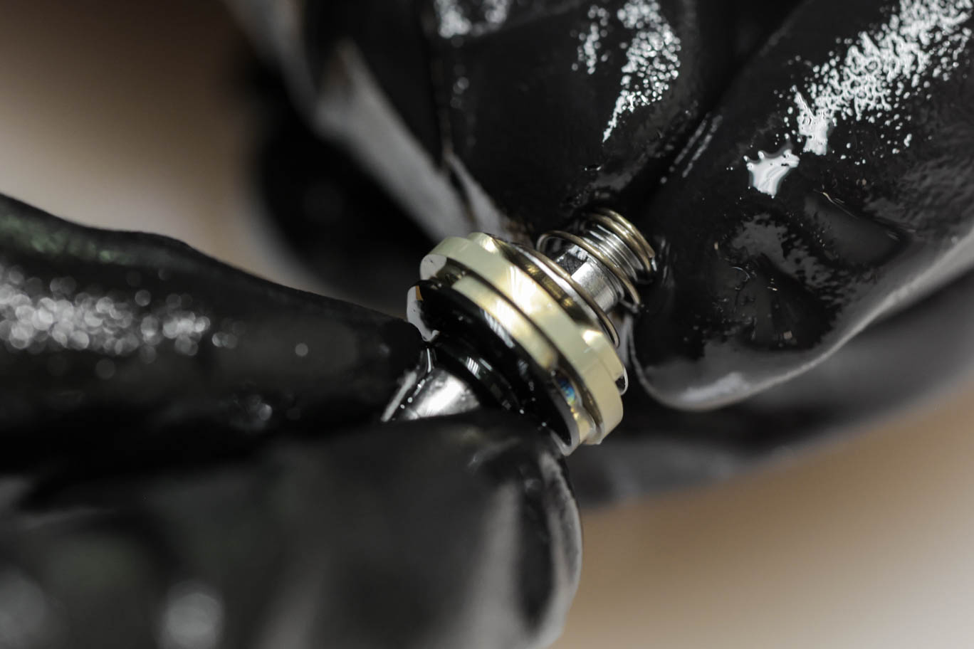
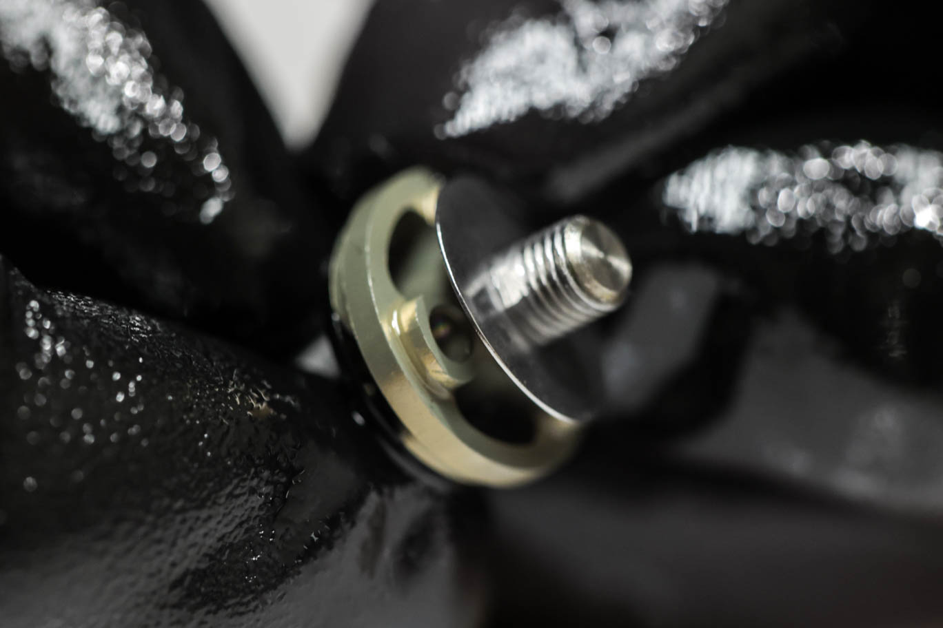
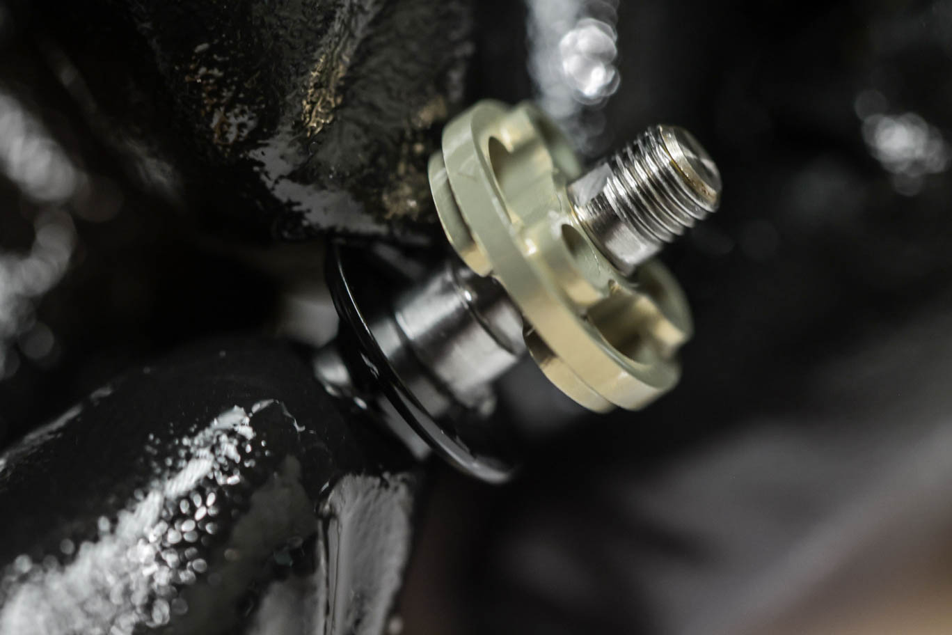
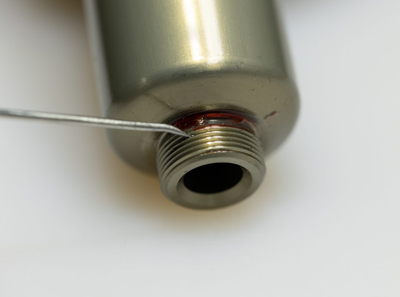
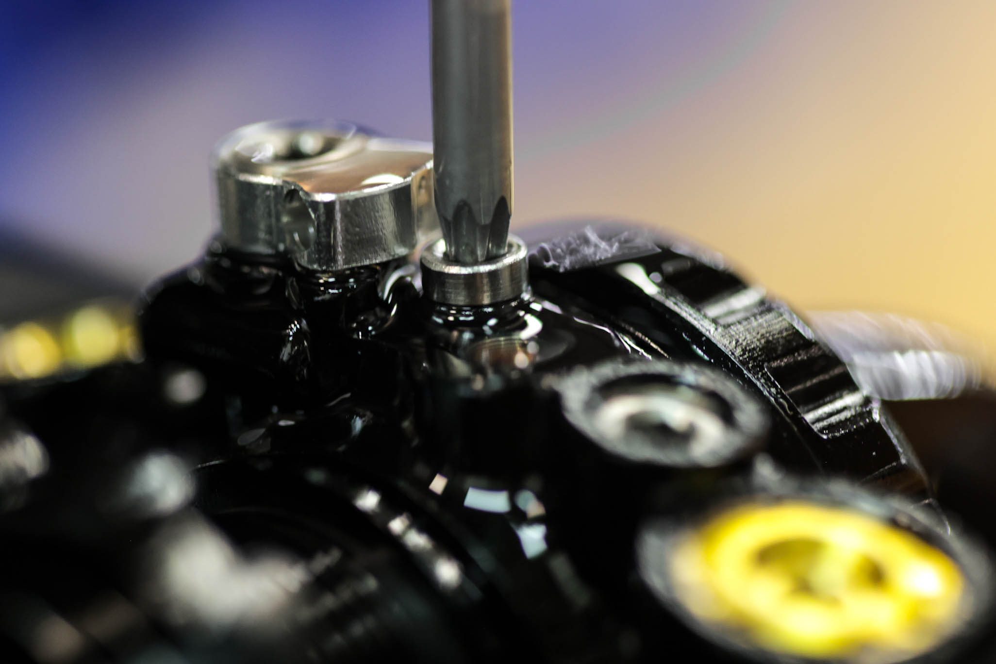
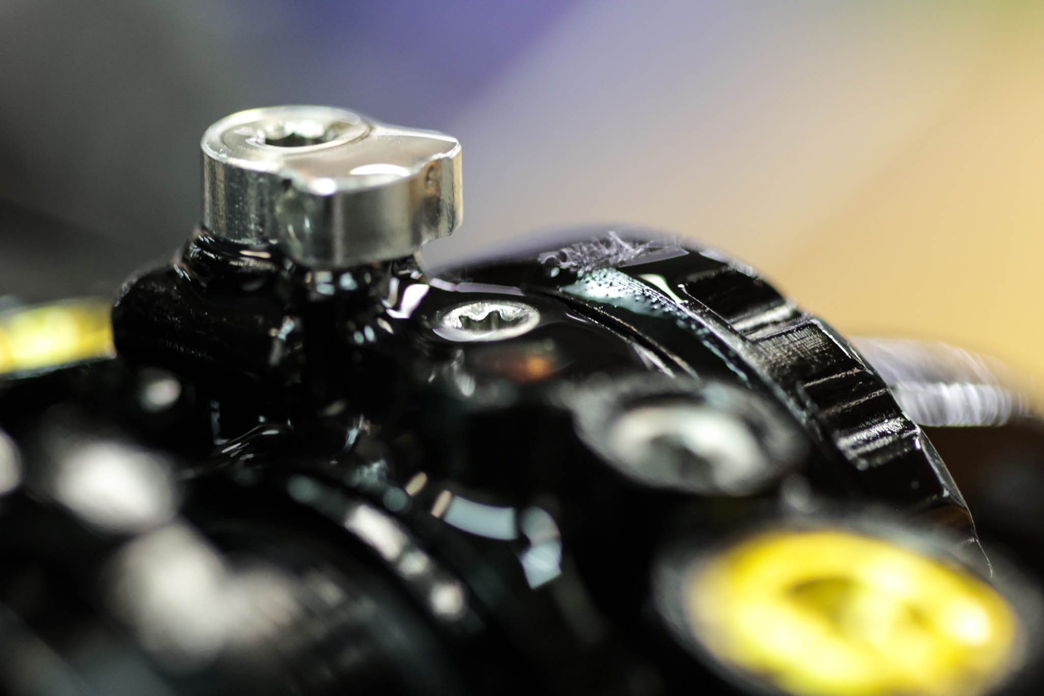
Leaving horizontal, disconnect fill machine. Unthread fill needle. Drip some oil on to top of fill. Install oil fill screw with T15. Insert new gas fill plug (.DB11115) leading with beveled edge. Thread gas fill plug screw in, leaving 2 threads exposed outside of the end eye.
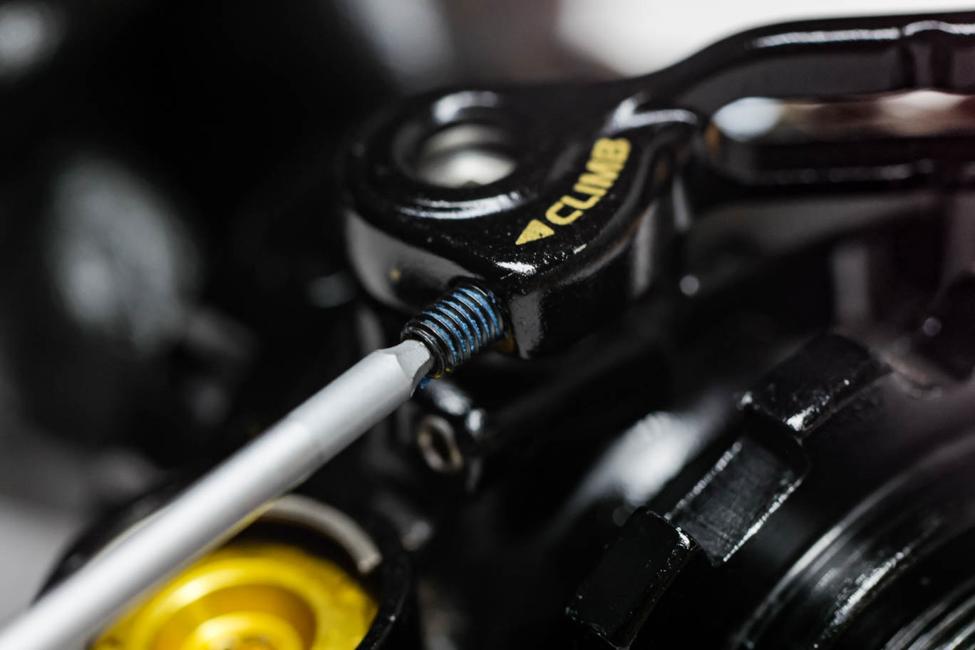
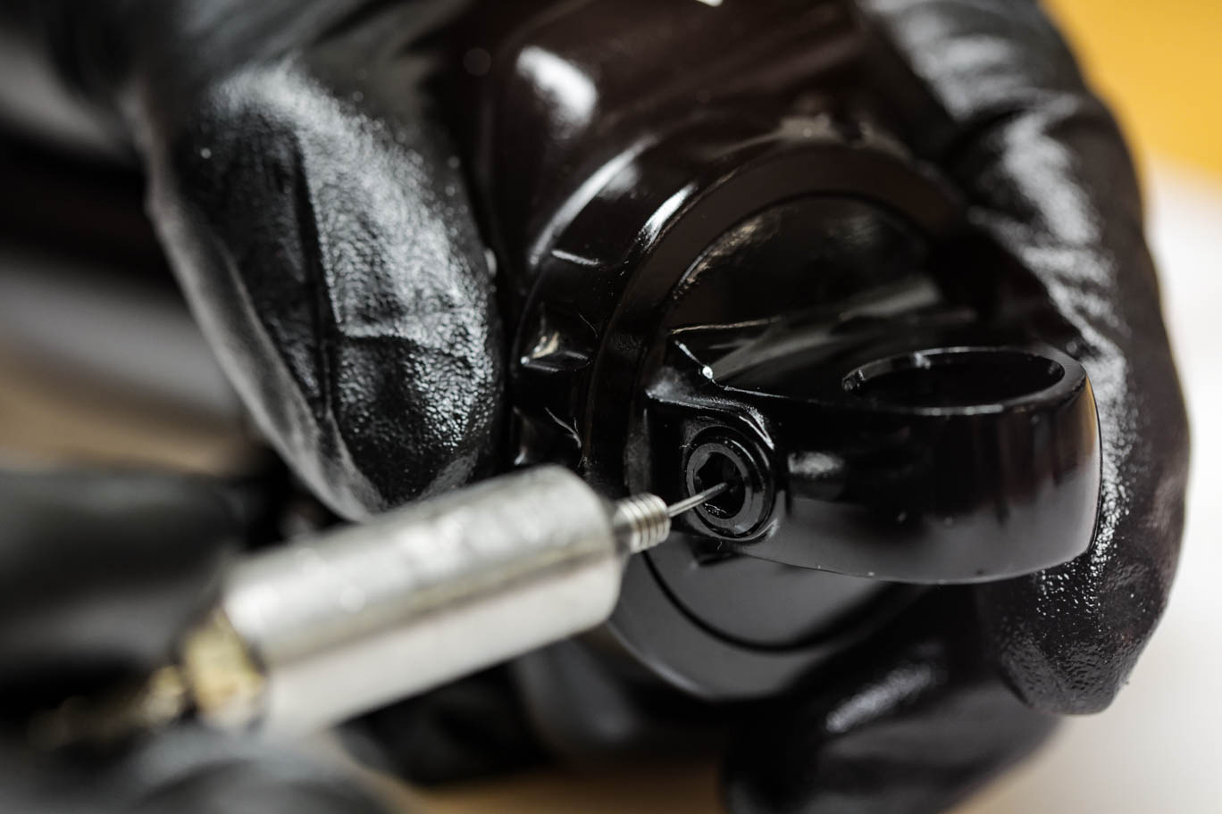
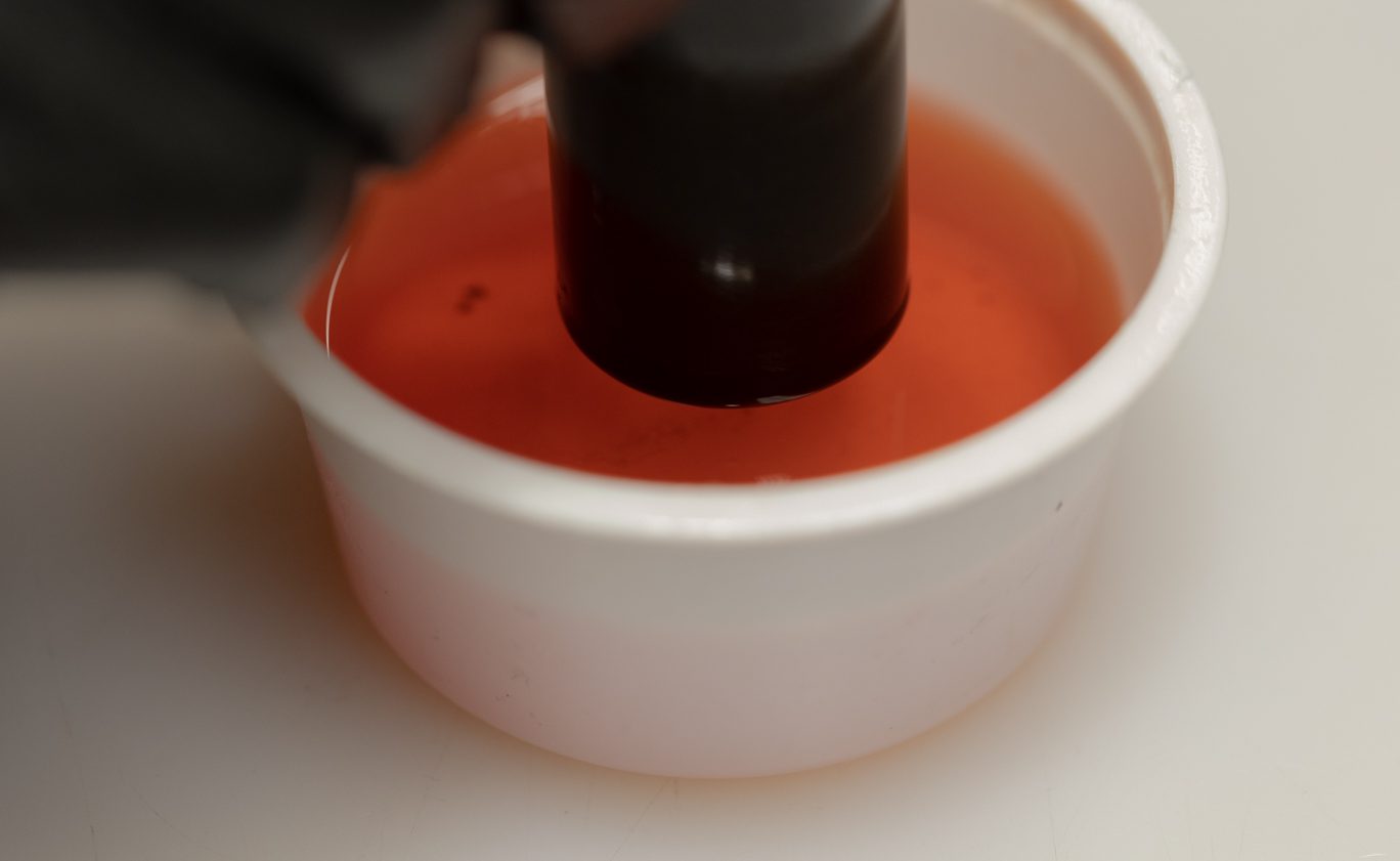
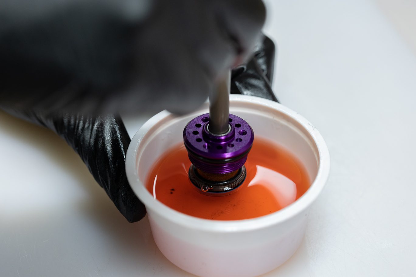
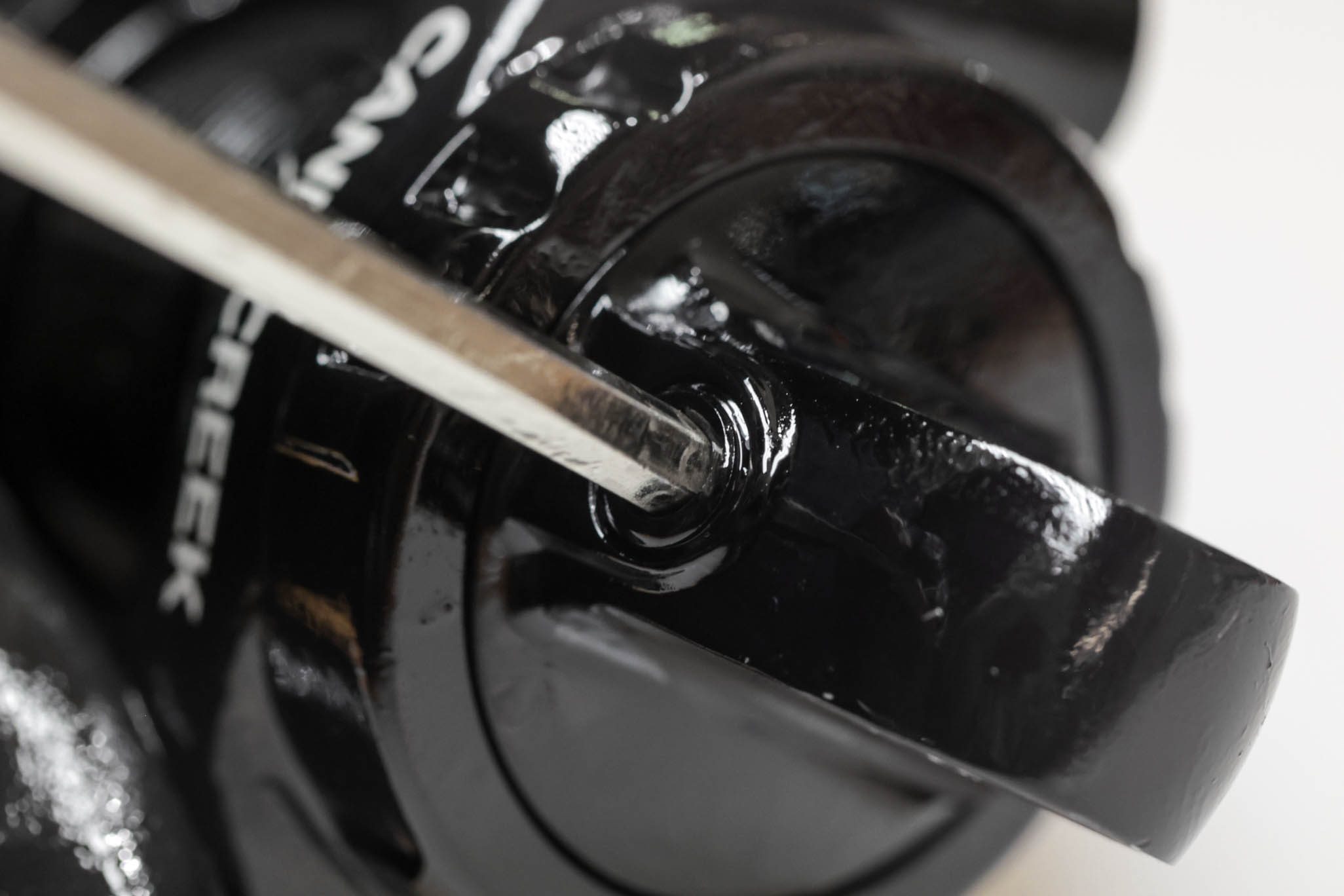
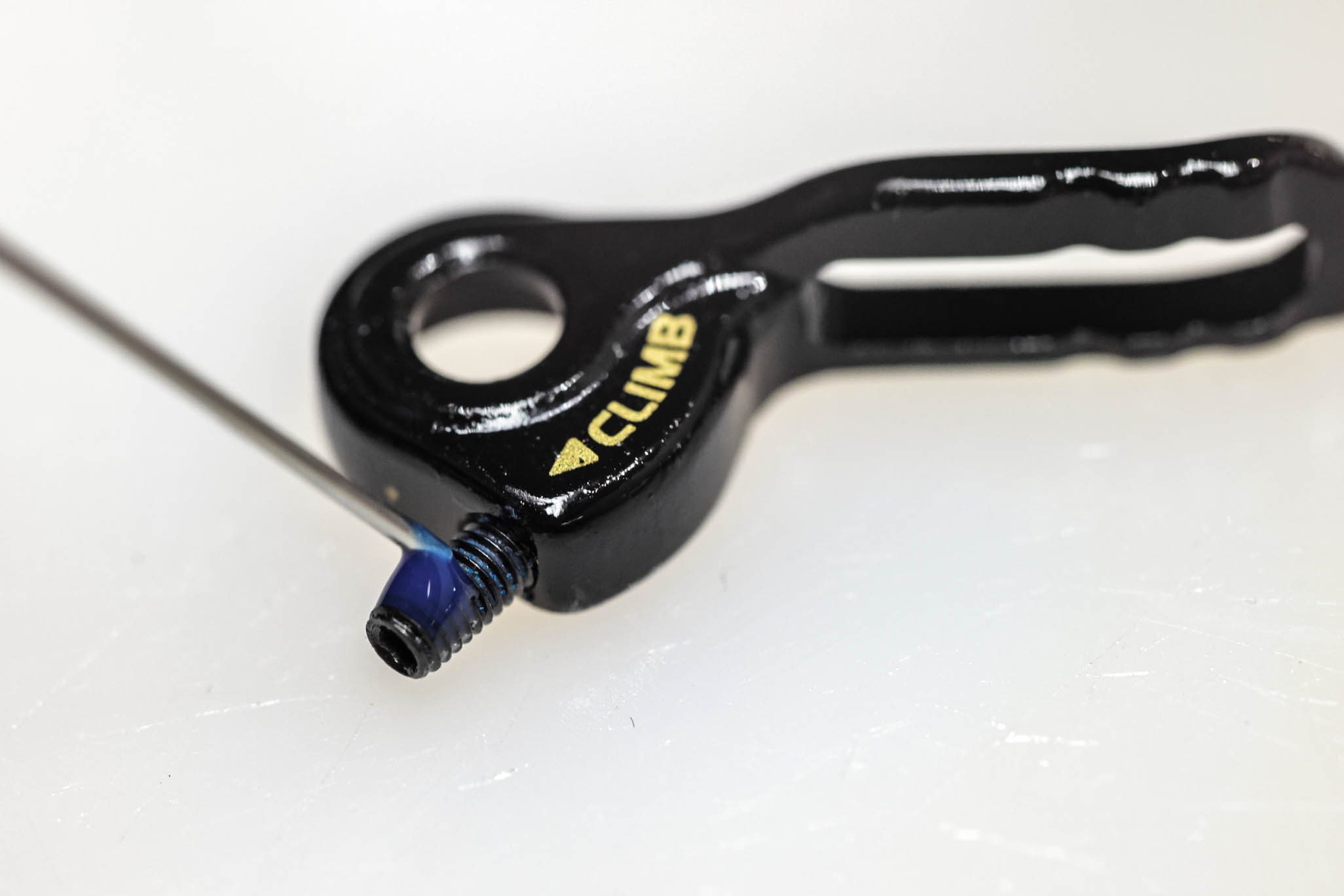
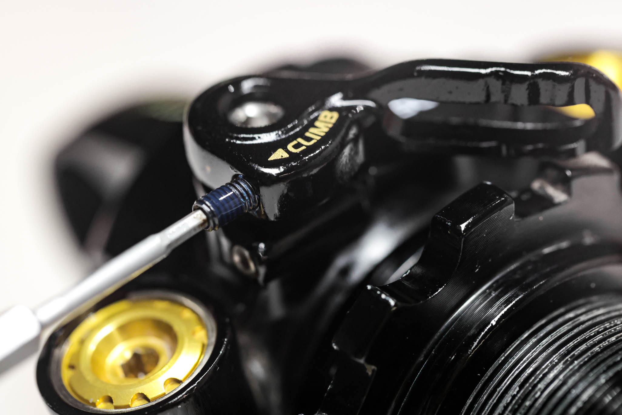
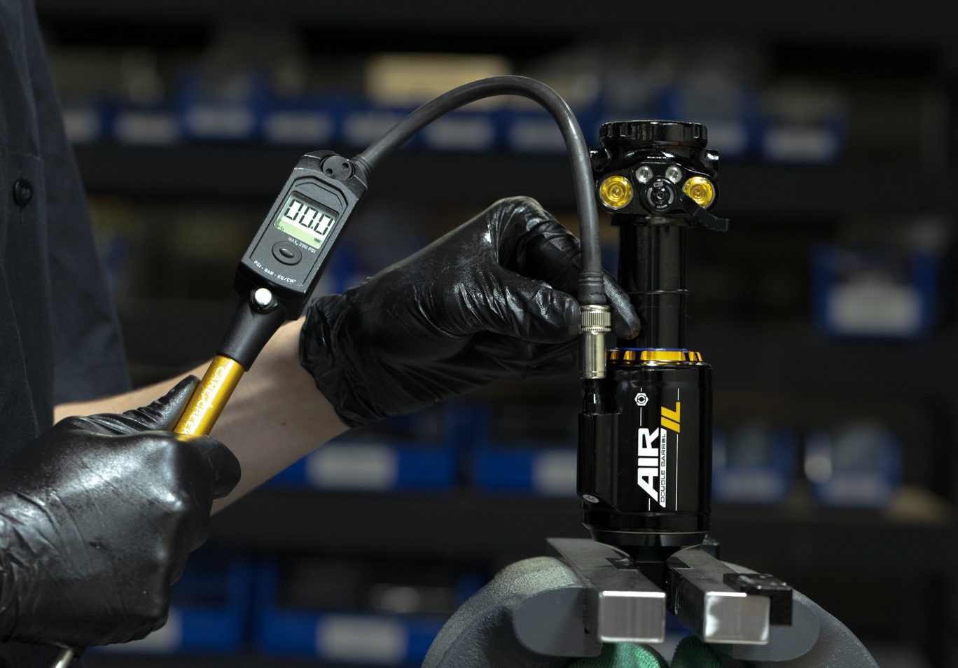
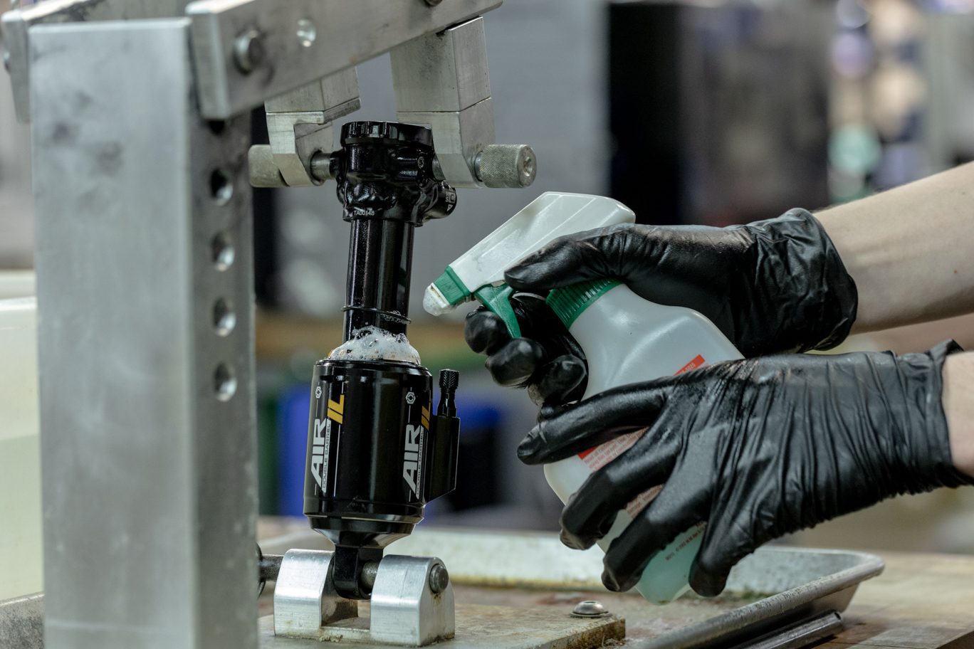
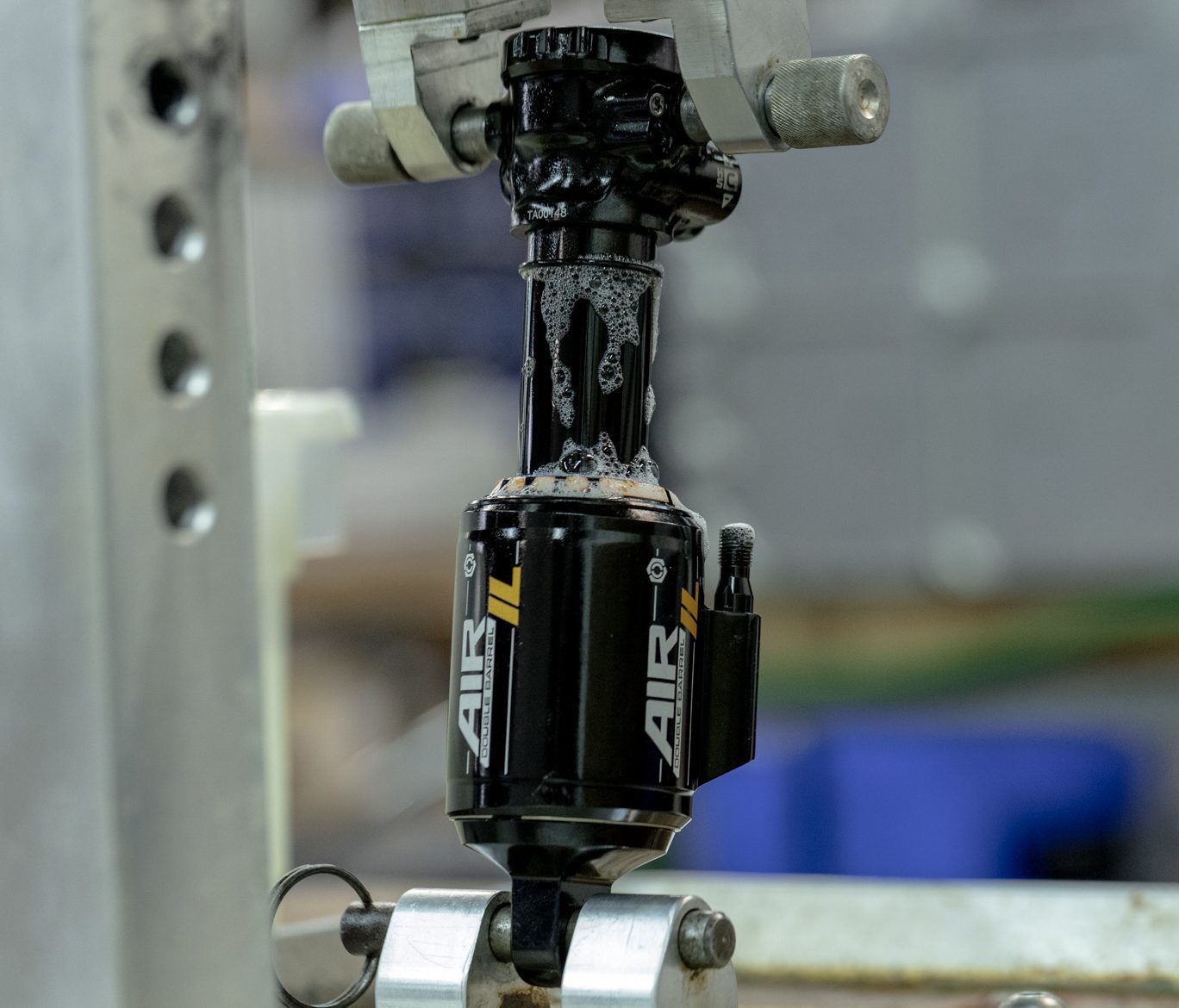
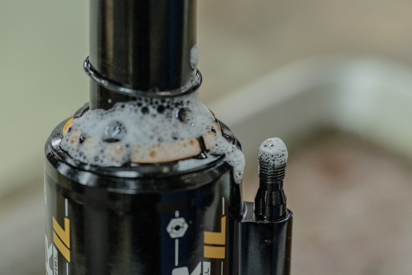
Submerge valve body in water to check for gas leaks. Rotate spool valve to down position. Reinstall oil fill cover. Apply a drop of blue Loctite (243) to Climb Switch set screw. Install Climb Switch on spool valve and install set screw. Torque to .16 Nm with 1.5mm Allen.
If mechanical dyno equipment is available, run shock on dyno at this point.
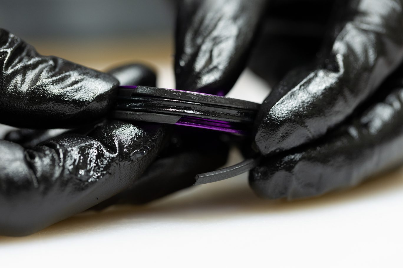
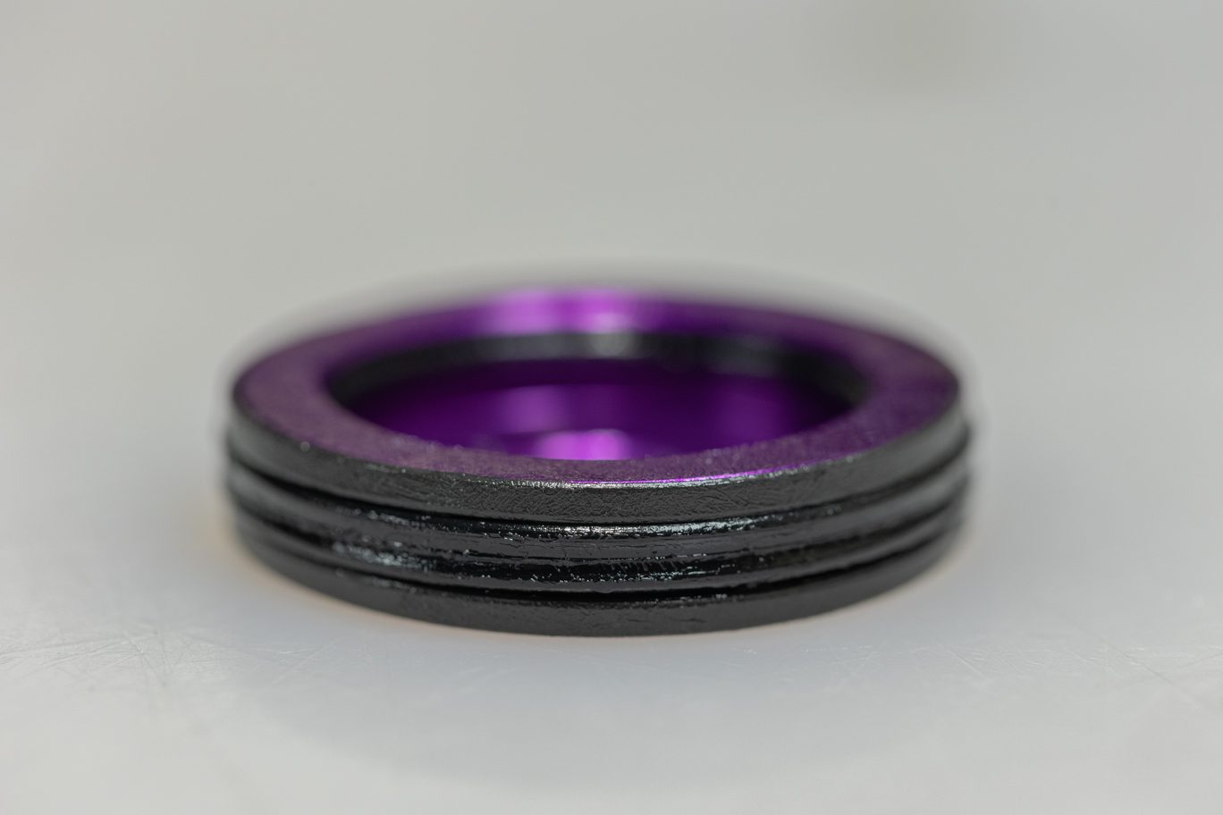
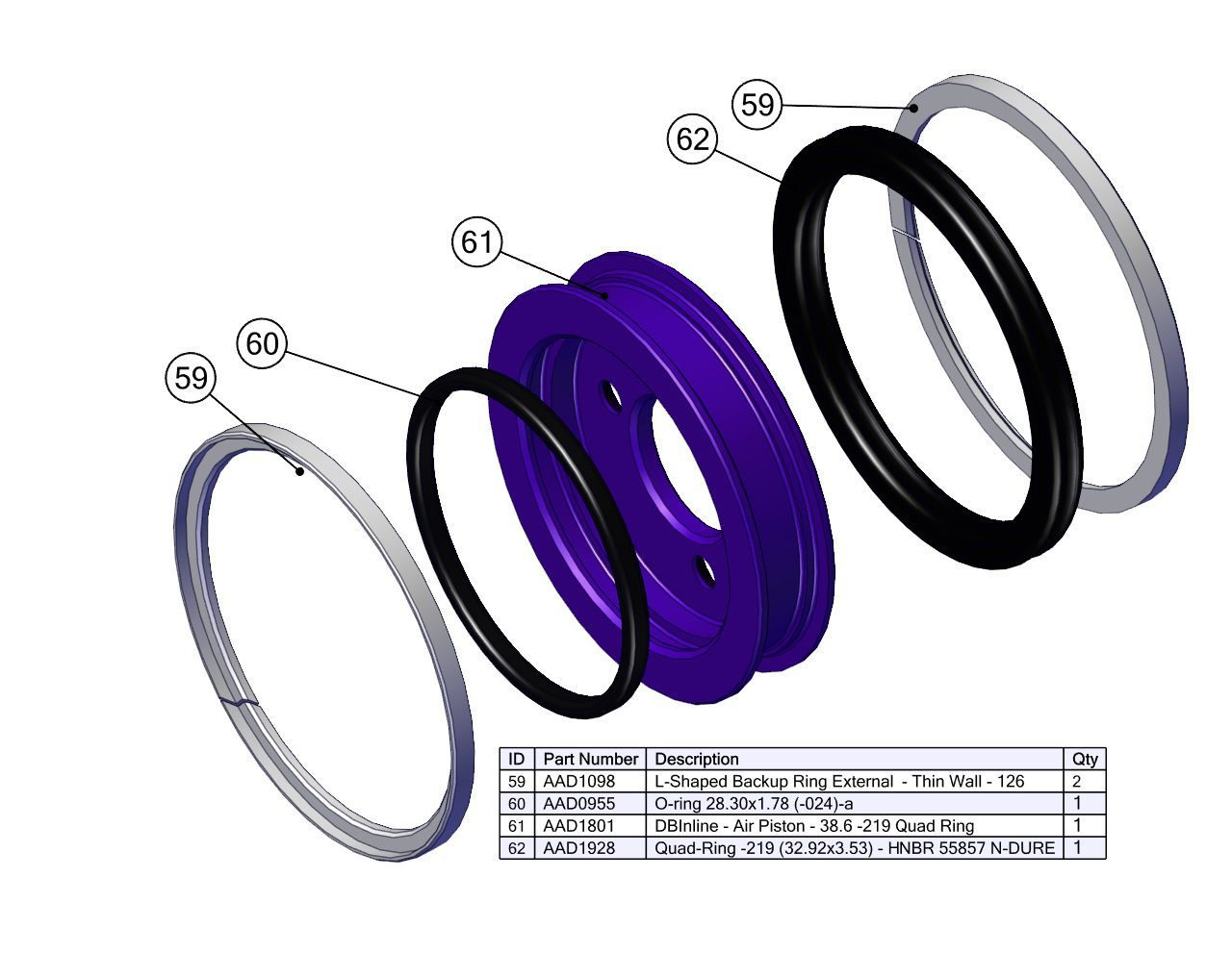
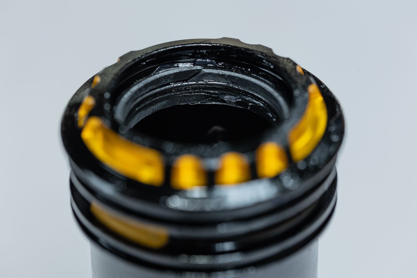
Ensure inner and outer air cans, end eye, and piston are thoroughly cleaned. Grease piston quad ring channel. Thoroughly grease all sides of quad ring (AAD1928). Install quad ring on piston channel. Pre-compress back up L-rings (AAD1098) to improve fit on piston. Install back up L-rings on either side of quad ring, ensuring that flat side contacts quad ring. Lightly grease and install piston o-ring (AAD0955) on bottom side of piston.
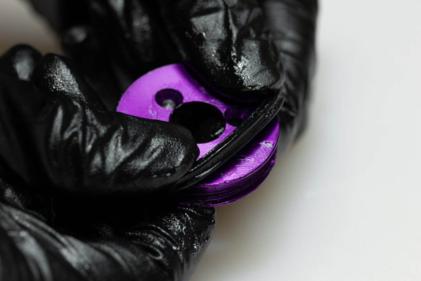
Grease lower channel on interior of inner air can.
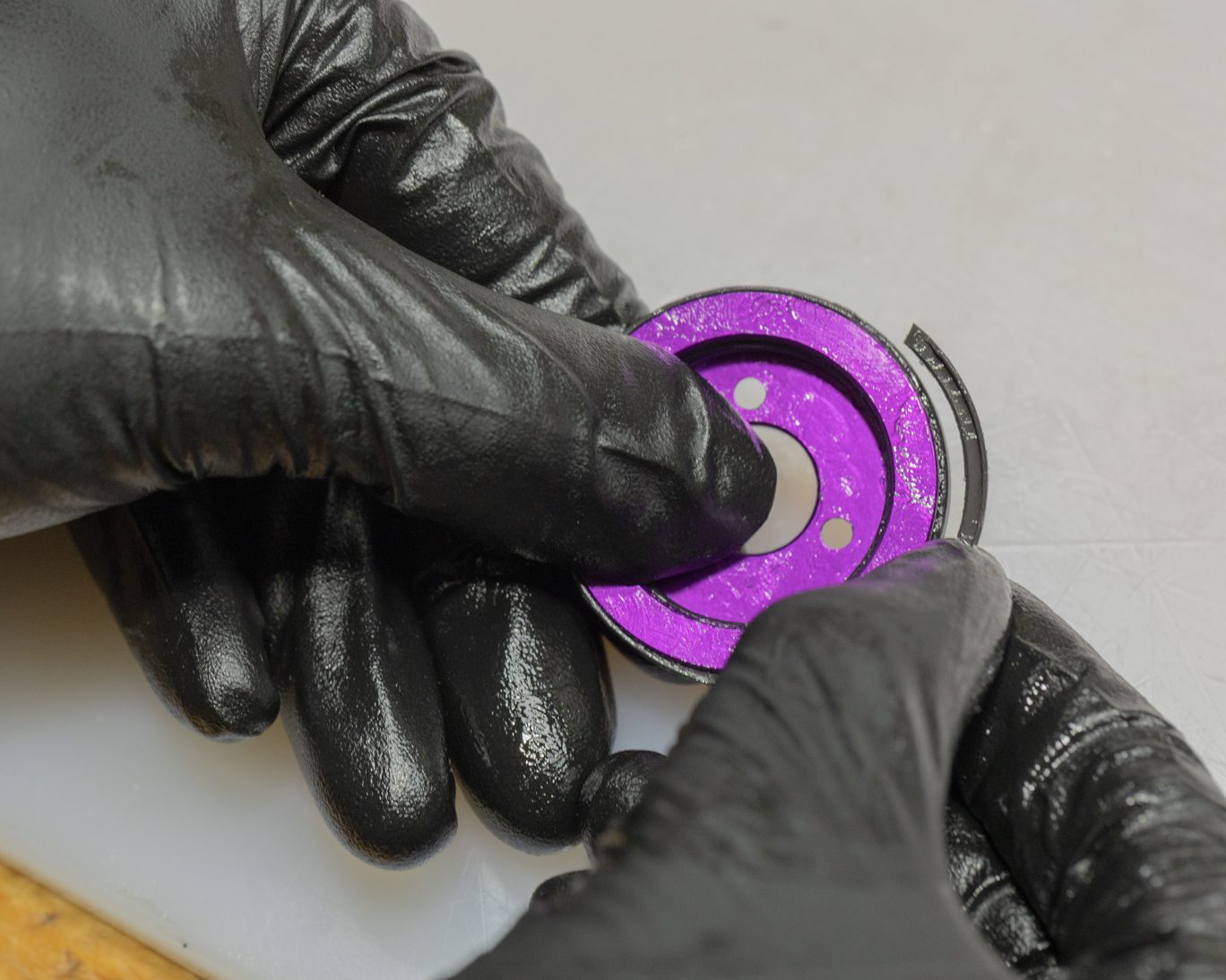
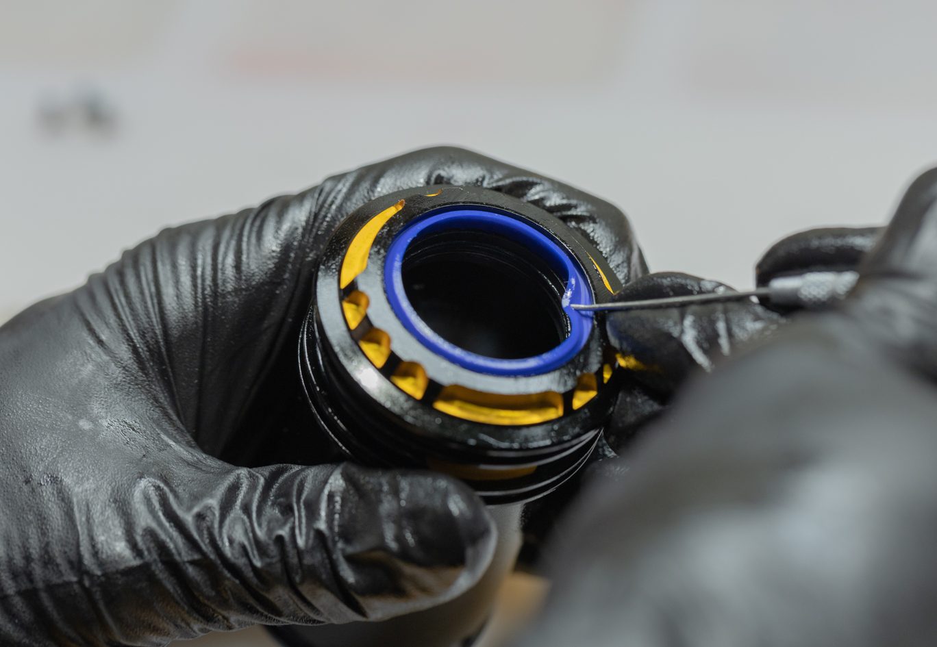
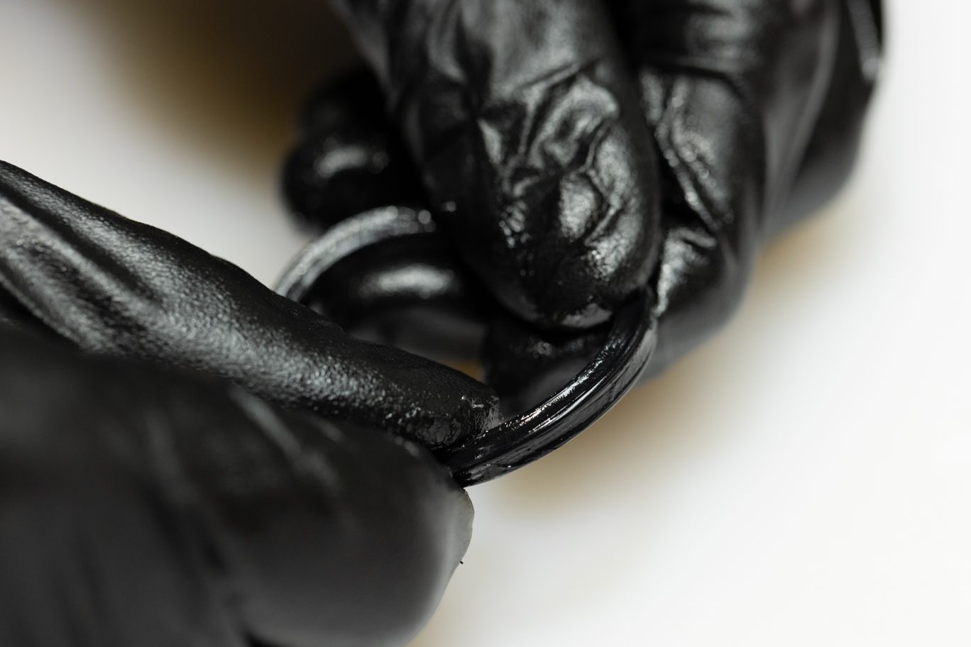
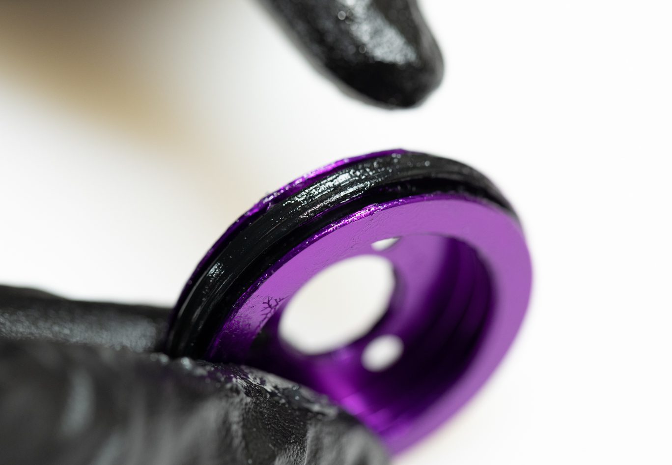
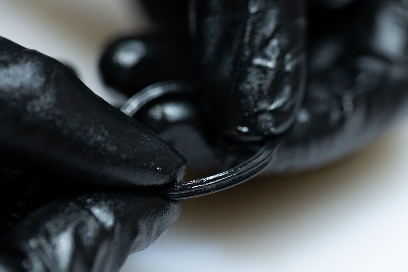
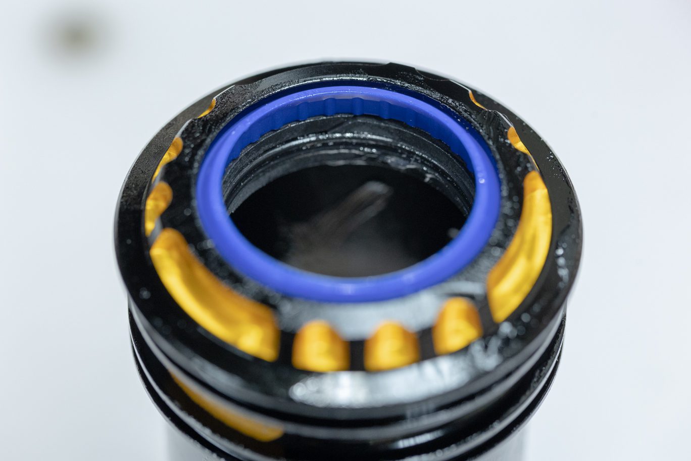
Install first L-ring (AAD1134) on lower shelf with flat side toward interior of channel. Thoroughly grease all sides of quad ring (AAD1846). Install quad ring into channel. Install second L-ring (AAD1134) on top of quad ring with flat side against quad ring.
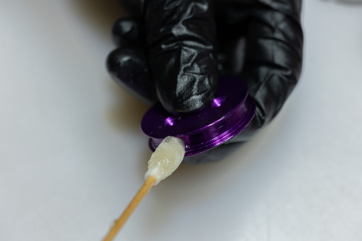
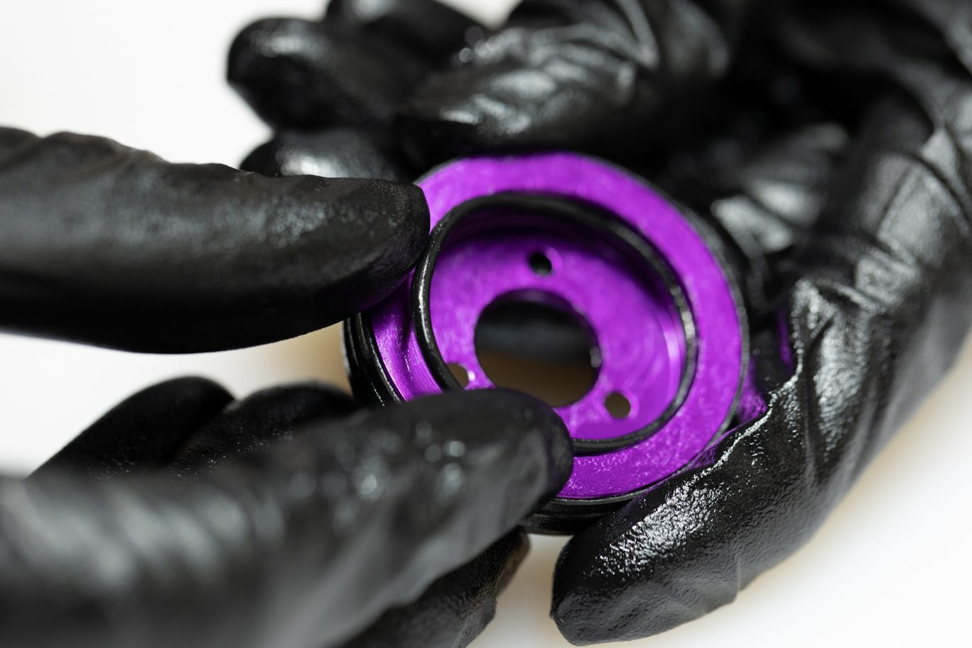
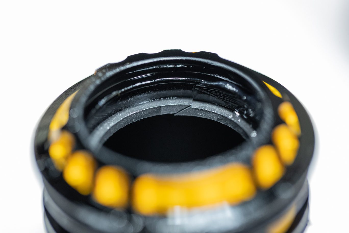
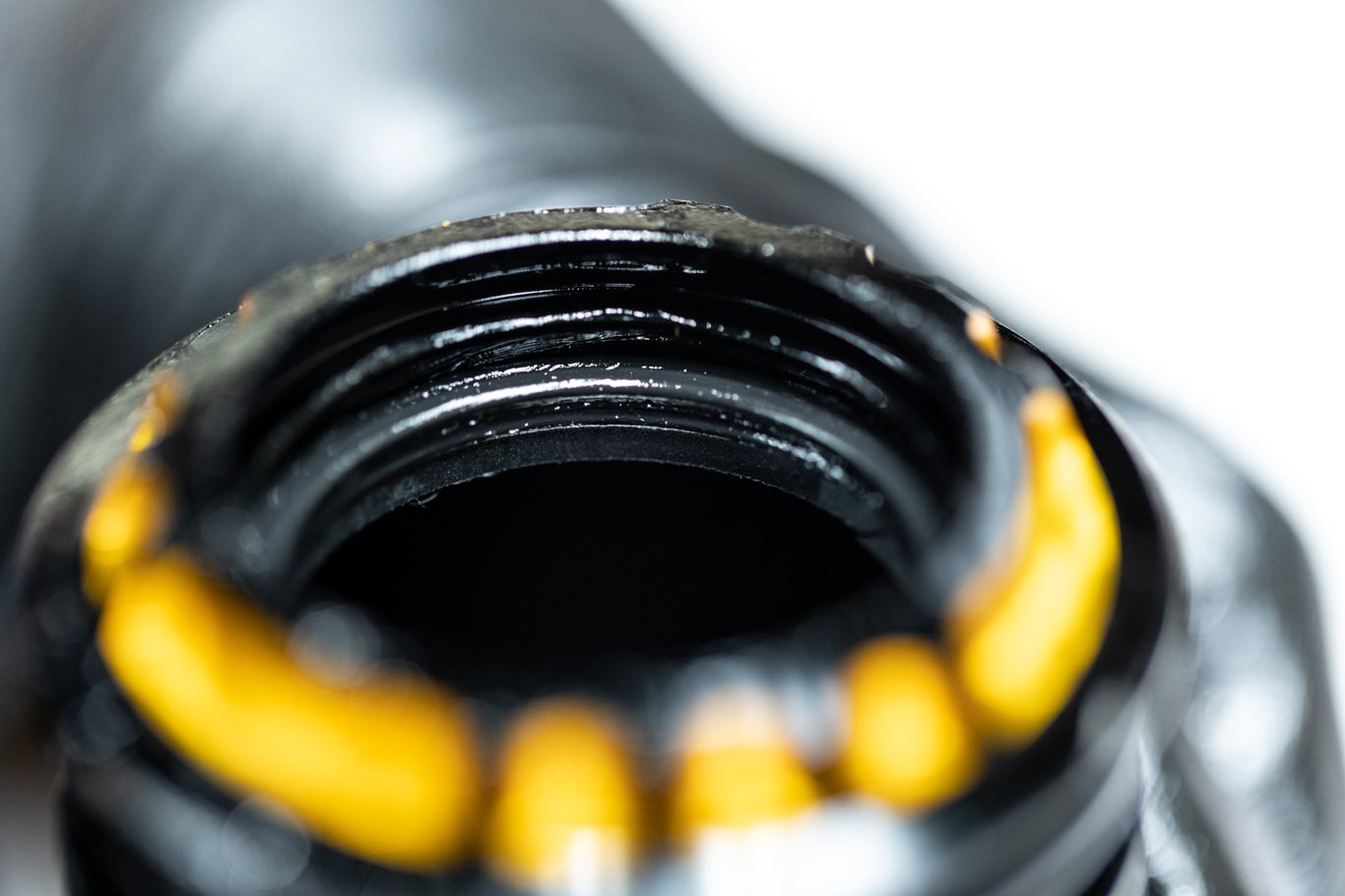
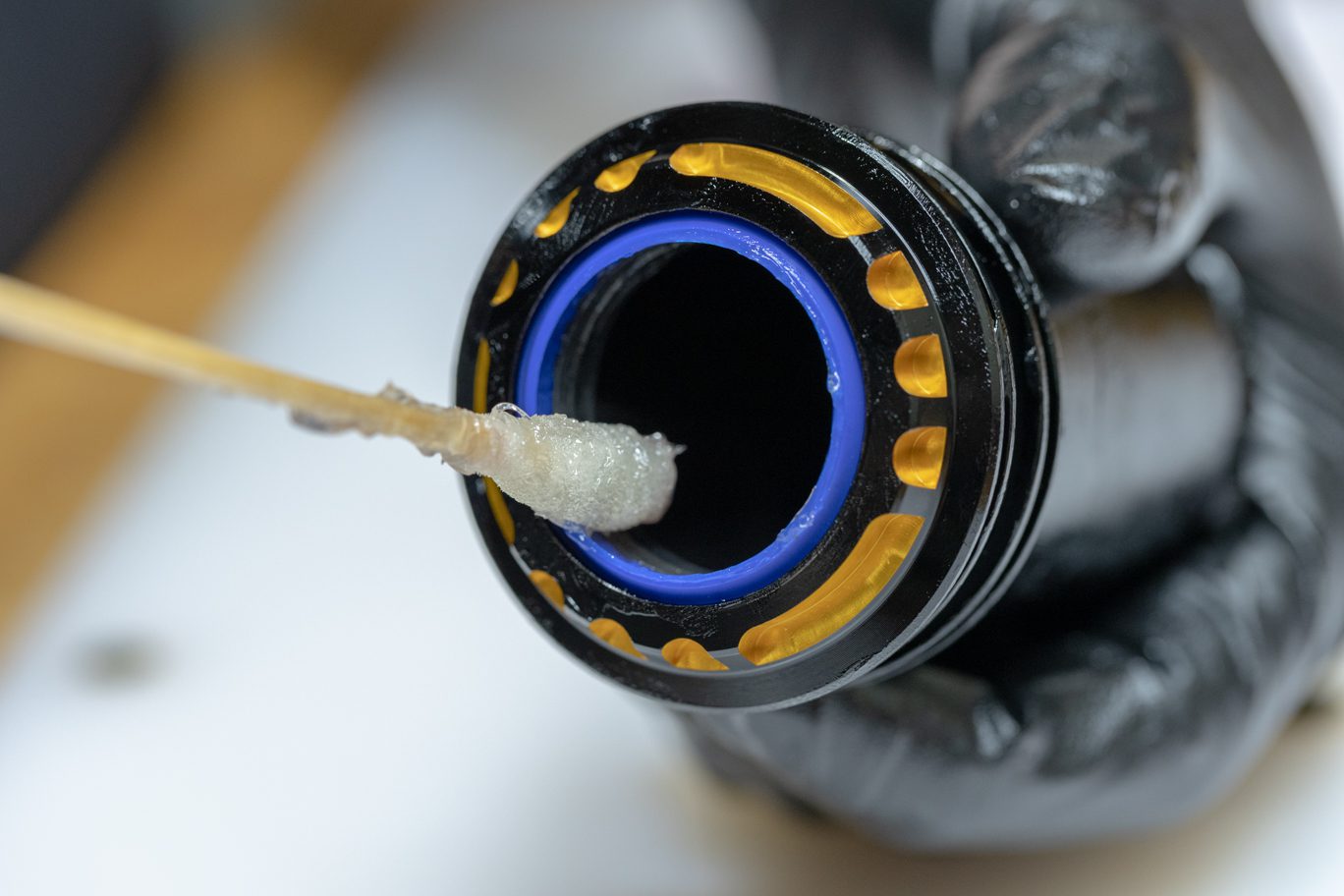
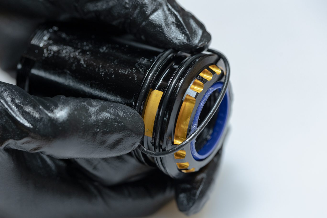
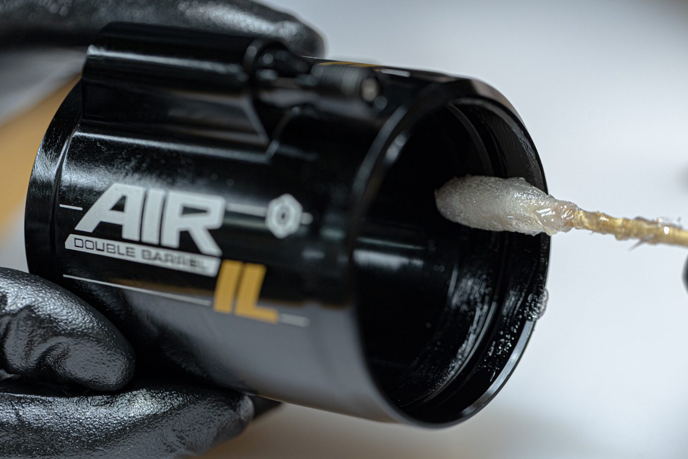
Install dry wiper seal (AAD0415) into top groove of inner air can. Thoroughly grease upper inner assembly of air can. Grease and install inner air can outer o-rings (AAD2142) on exterior of air can in the two grooves. Lightly grease the lower interior inner air can. Excess grease can clog charge port.
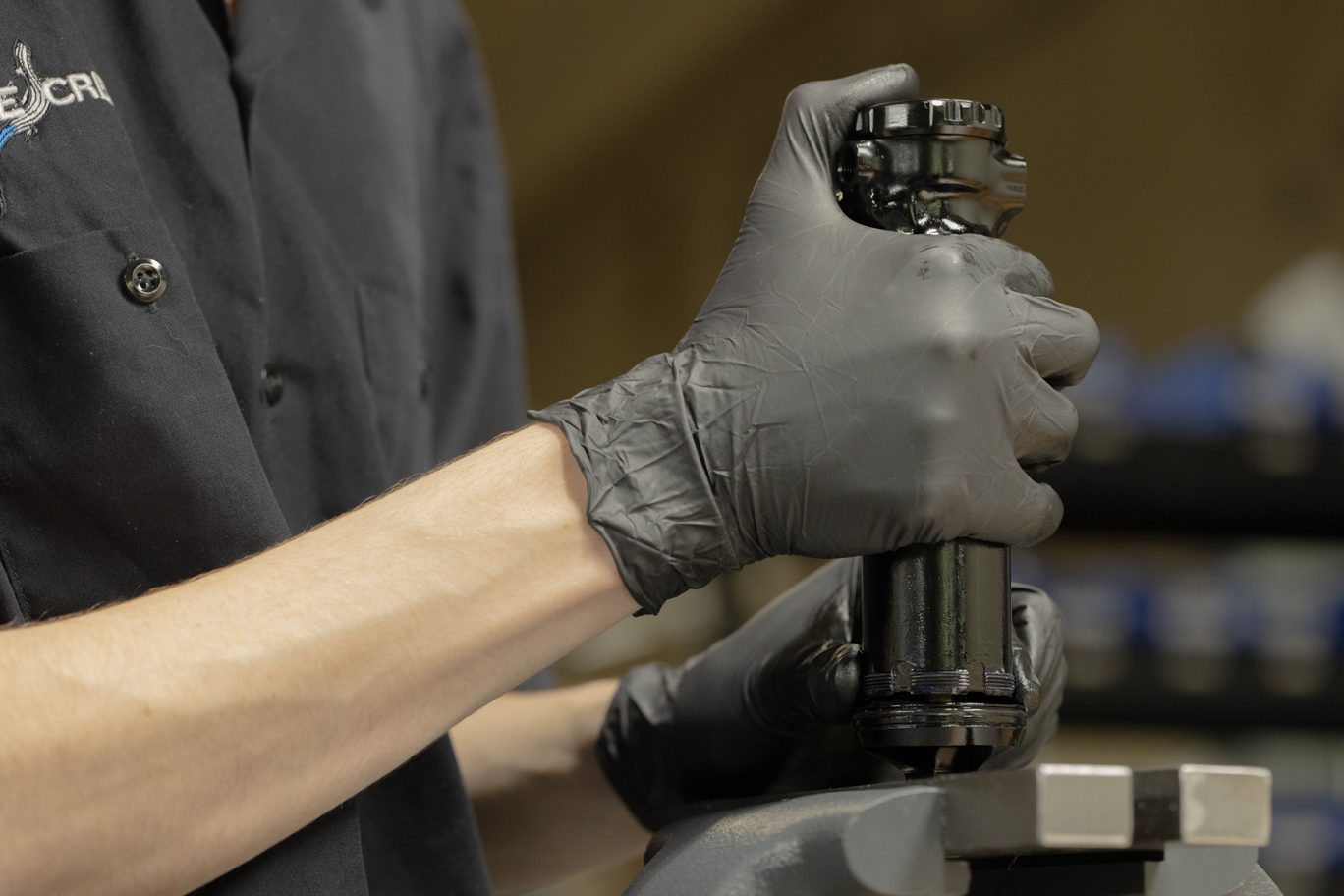
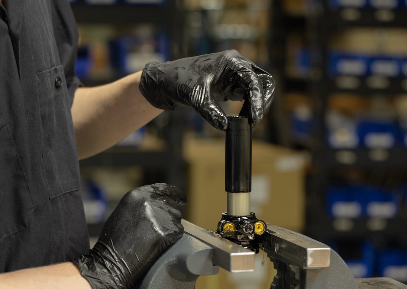
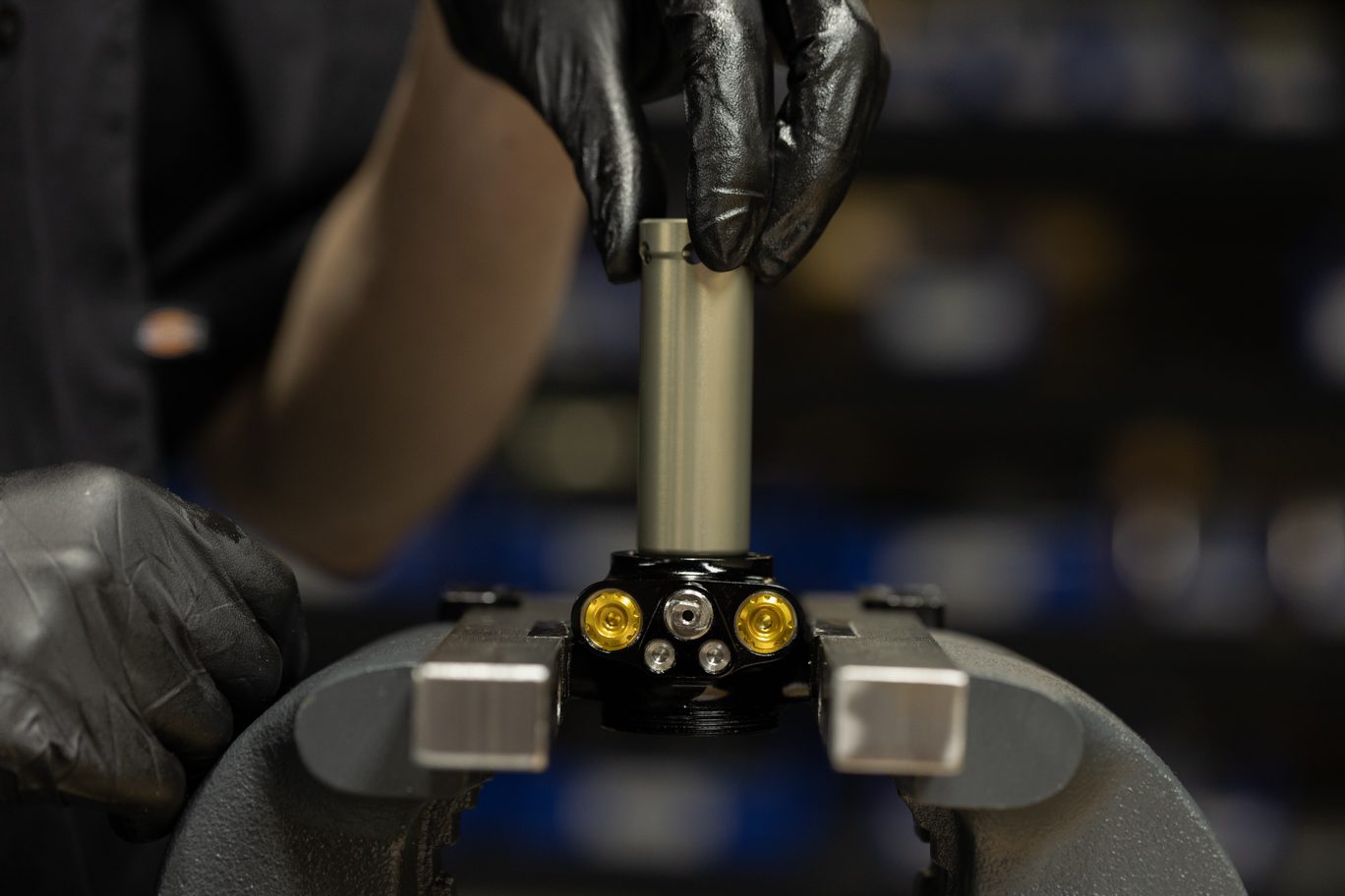
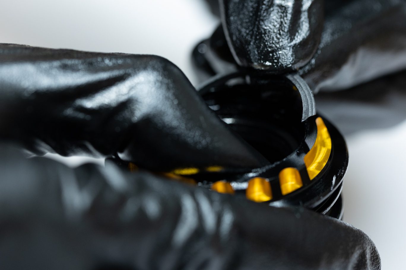
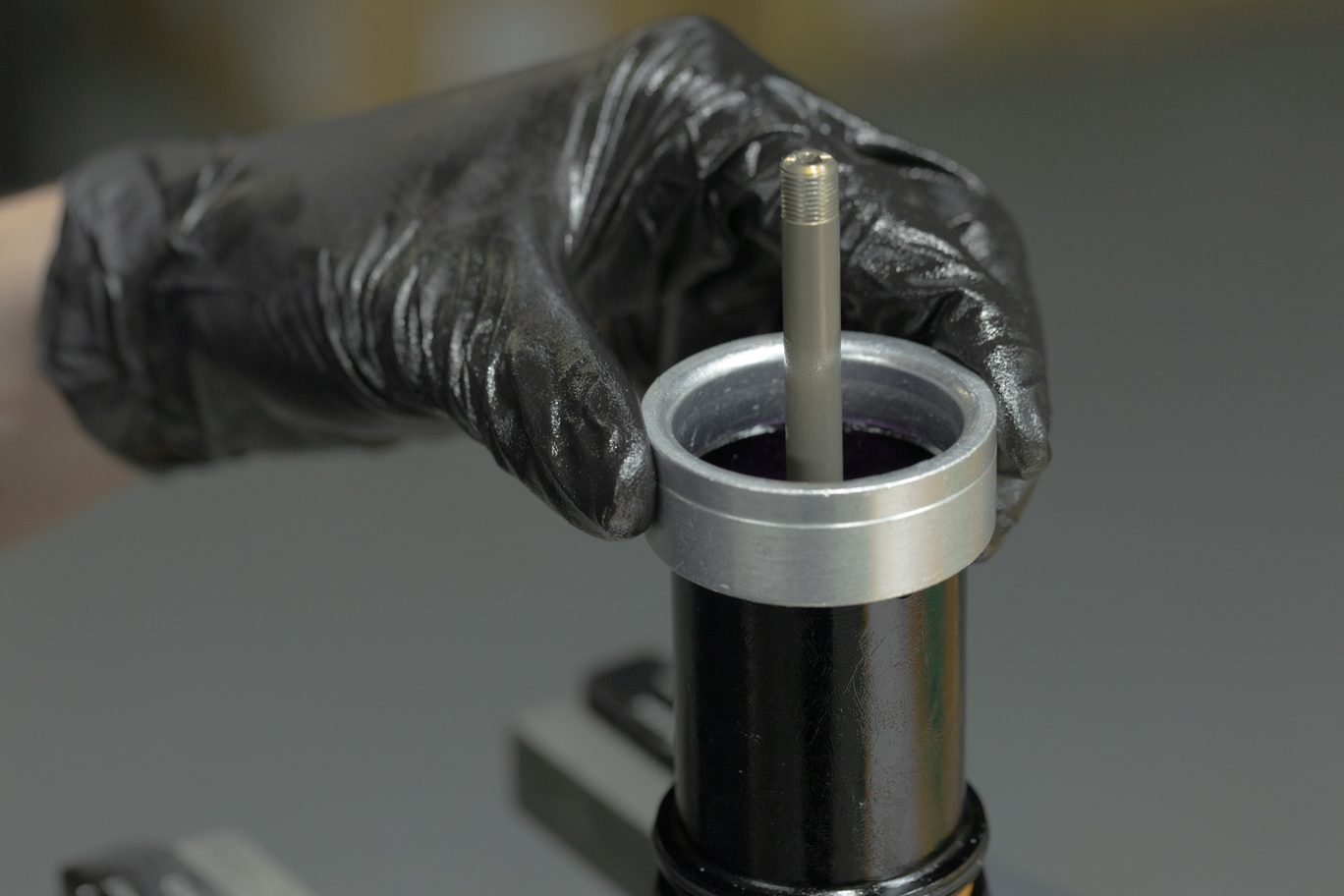
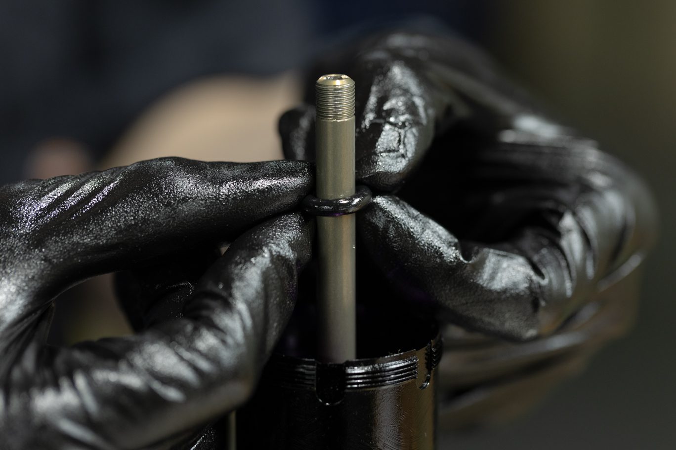
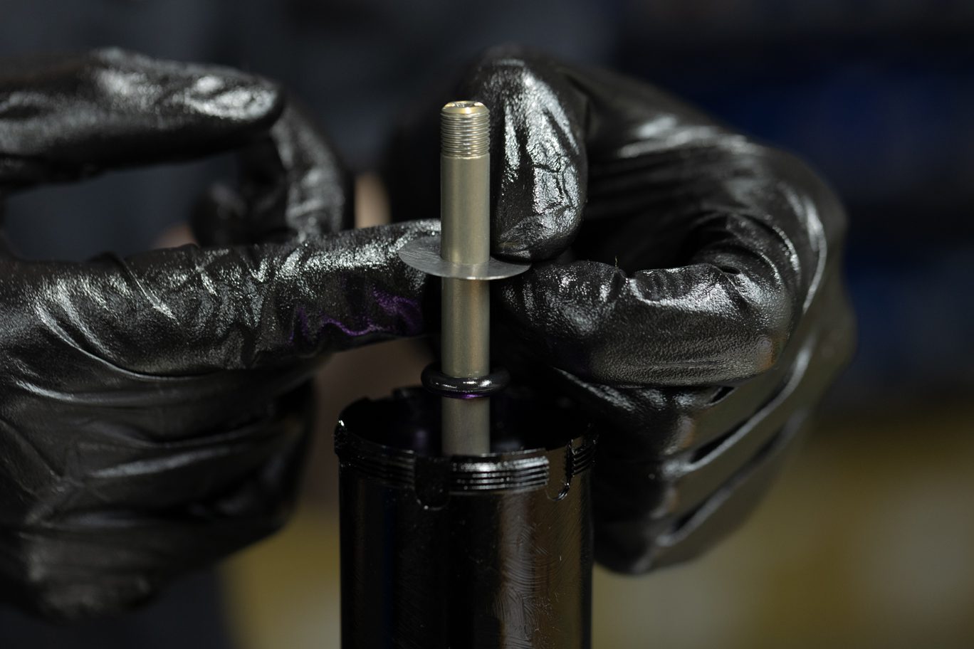
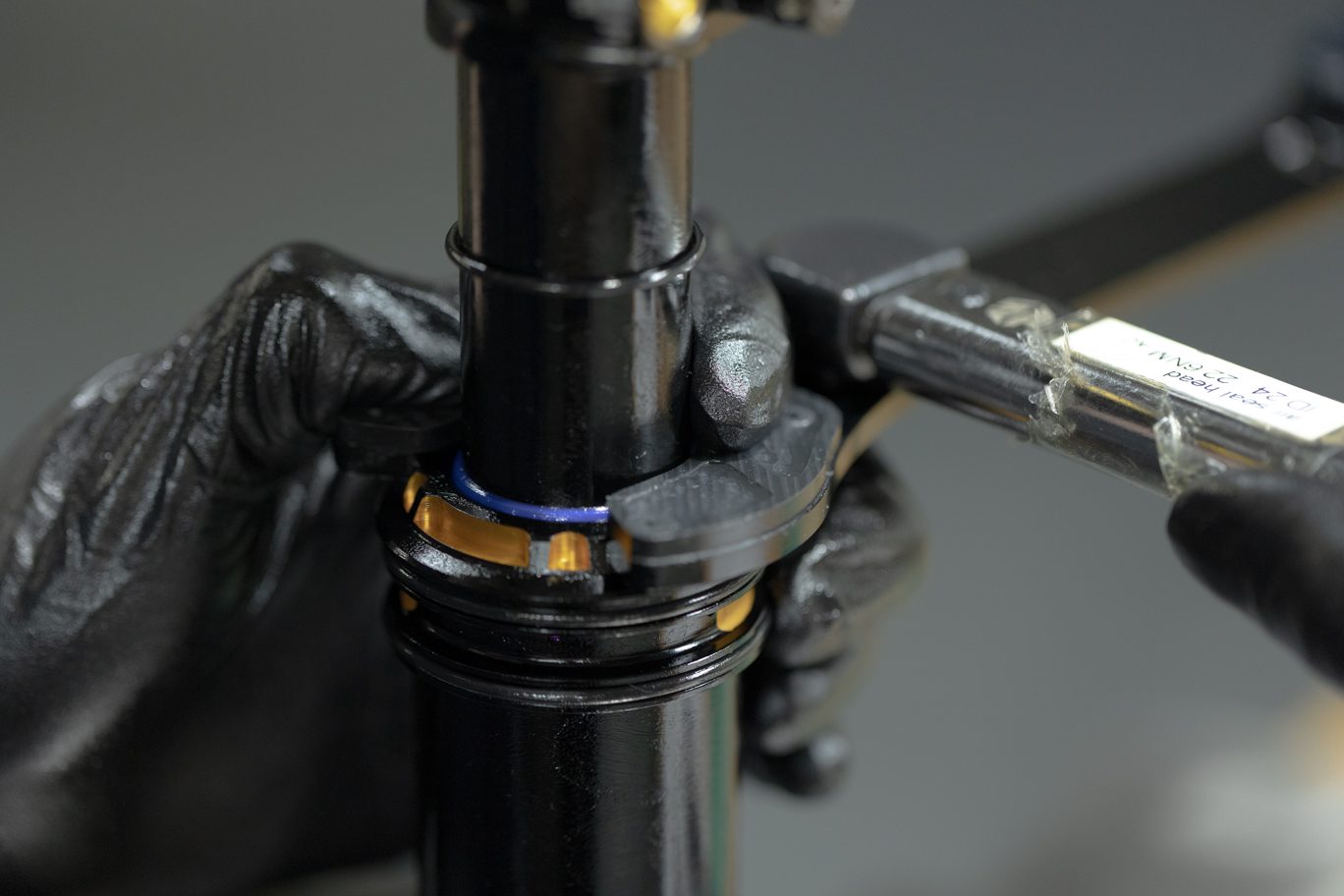
Clamp valve body end eye in vise or use Keith Cradle. Place Oil Seal Head Bullet (AAD1193 or AAD1182) onto shaft. Install sag indicator o-ring (.DB11108). Install inner air can. Gently work the can past the bullet tool onto the body with a slight rotation and even pressure.
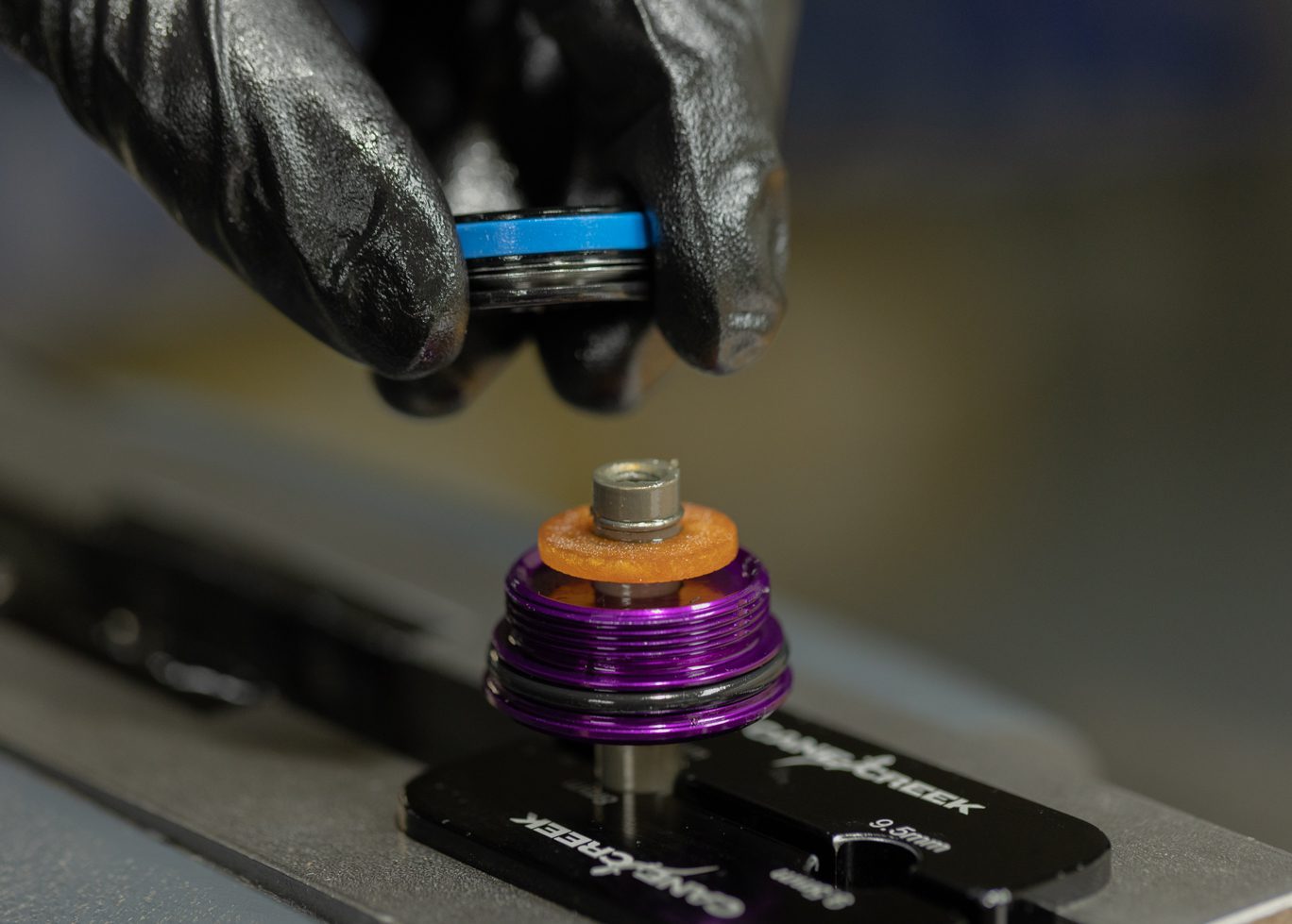
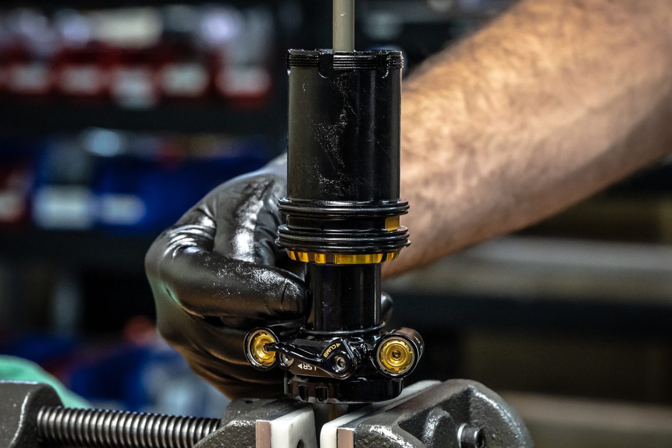
Thoroughly grease the exterior of air piston. Apply blue Loctite (243) to three air piston set screws. Place Air Piston Funnel (BAD1459) on inner air can. Set inner air can halfway on outer damper tube to allow for space to install air piston. Install piston with set screw holes facing out. Gently work piston past funnel into inner air can. Bottom piston onto seal head. Once flush with seal head, rotate inner can and piston to align screw holes with seal head threads.
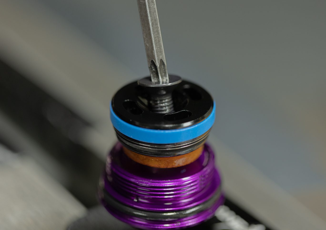
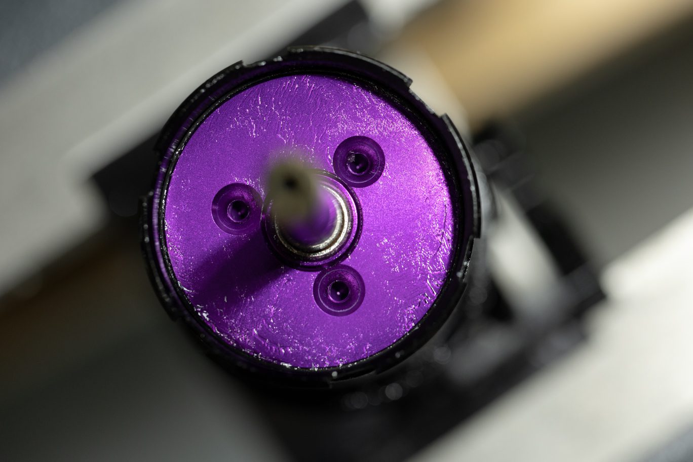
Install piston set screws. Torque to 3.2 Nm with T10.
Reinstall bottom out bumper, shim and stroke reduction (if present). Apply blue Loctite (243) to shaft threads and end eye threads. Thread end eye onto the shaft. Clamp shaft into vise with shaft clamp allowing space for end eye to clear vise when tightened. Using 1/2″ crowsfoot, torque end eye to 4.8 Nm. Clean any extra Loctite from shaft and end eye.
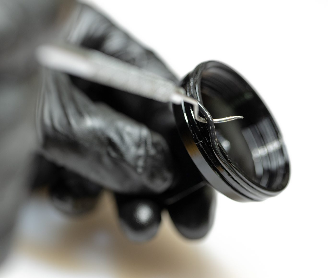
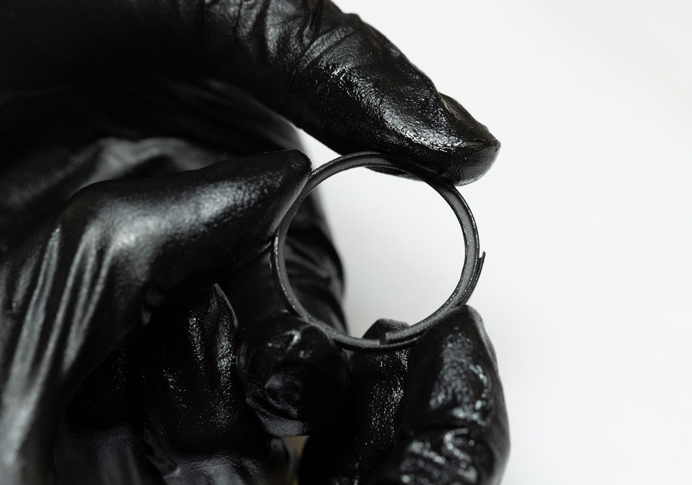
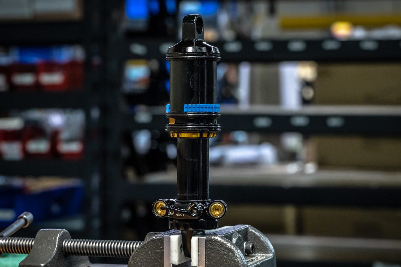
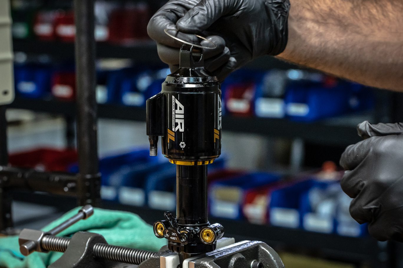
Clamp valve body end into vise. Work outer air can gently past o-rings. Note correct orientation of air can and reinstall any volume reduction. Final o-ring will be tight. Strap wrench may be necessary. Engage Climb Switch to aid installation. Ensure valve is oriented away from Climb Switch. Install outer air can retention clip.
Set adjusters to factory neutral: HSC & HSR 2.5 turns from full bottom (or 2 turns from full open); LSC 11 clicks from full bottom; LSR 13 from full bottom. Using hand dyno, test shock for function. Ensure Climb Switch engages and operates properly. Turn individual adjusters to test each one. Set back to original tune if desired.
Install any bushings and hardware.

Monday: 10:00 am – 5:00 pm
Tuesday – Thursday: 10:00 am – 5:00 pm
Friday: 10:00 am – 5:00 pm
Saturday – Sunday: Closed