We Are Open and Have Returned to Normal Operations
Previous slide
Next slide
May 2023 orig.
Please dispose of all waste products and materials through proper channels to avoid contamination of the environment.
Any damage or issues resulting from improper service will not be covered by warranty. If you have a shock still in its original warranty period and do not wish to void your warranty, please contact an authorized Cane Creek service center.
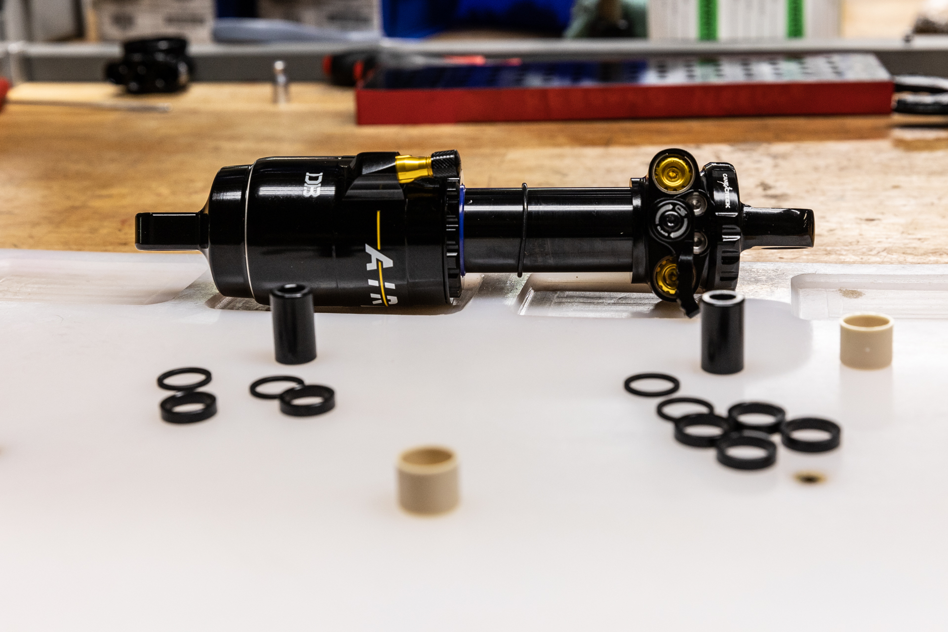
This service covers changing stroke ONLY on a new Air IL shock. As o-rings are considered new as part of this service, they will not be replaced. If this stroke change is being done on an older shock, a full 100 hour service is recommended.
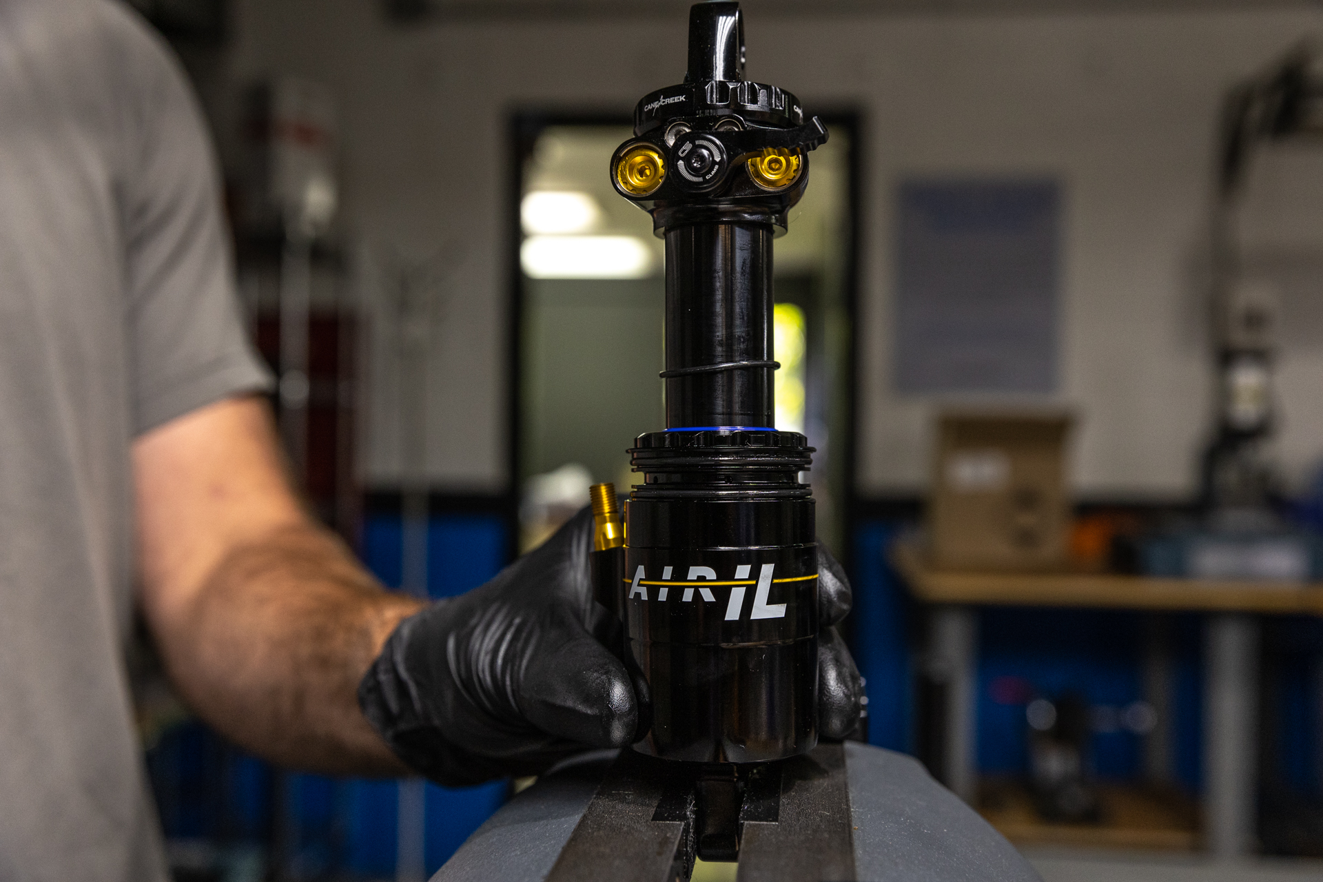
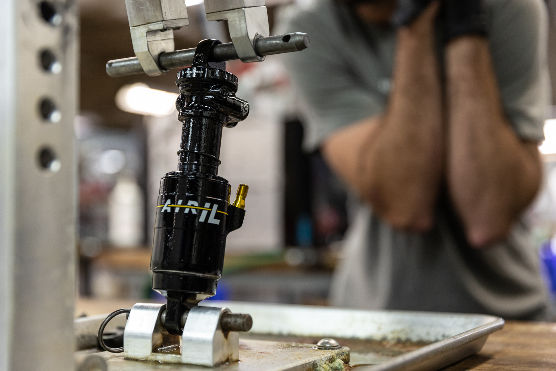
The stroke change procedure is the same for Standard and Trunnion mount shocks. Images of both are used interchangeably here.
No service kits required. If reducing stroke, 2.5mm stroke reduction pucks (AAD2578) are required.
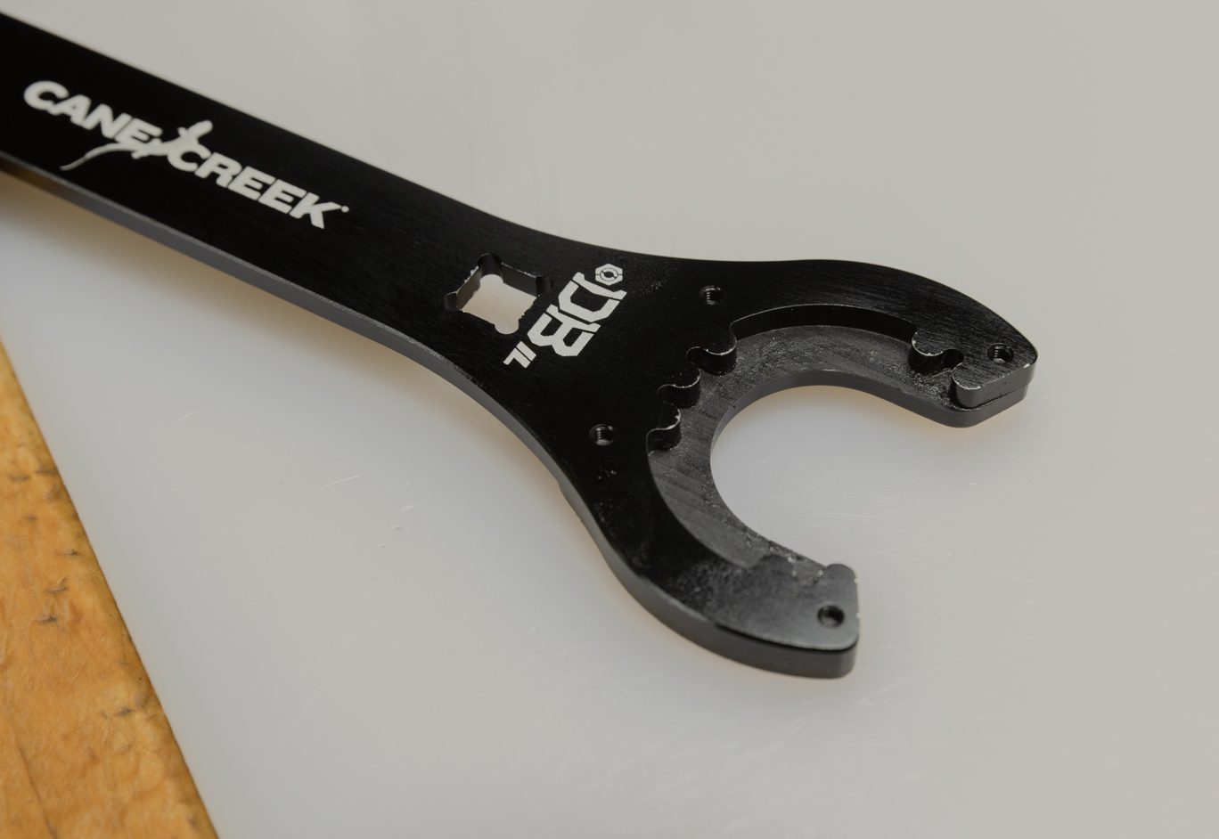
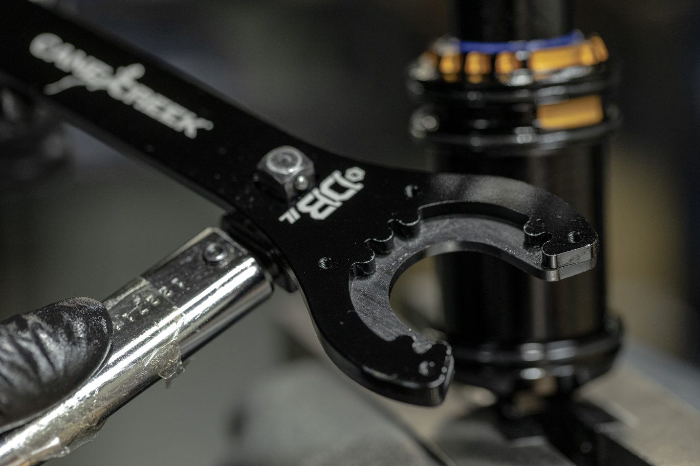
BCD0344 – Kitsuma/DBair/DBair IL Air Seal Head Tool
Torque & Loctite Chart
| Part | Torque Spec | Loctite Spec |
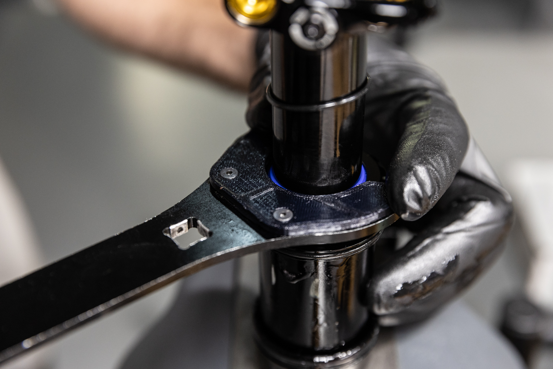
| Inner Air Can/Air Seal Head | 22.6 Nm | None (PolyLube) |
Oil Chart
| Oil Location | Oil Type | Oil Amount |
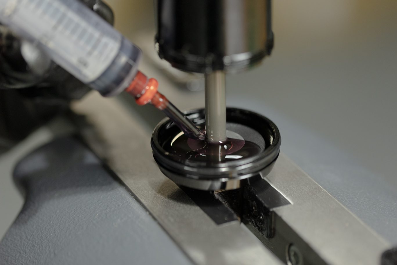
| Air Can | Royal Purple 10w-30 | 5 mL |
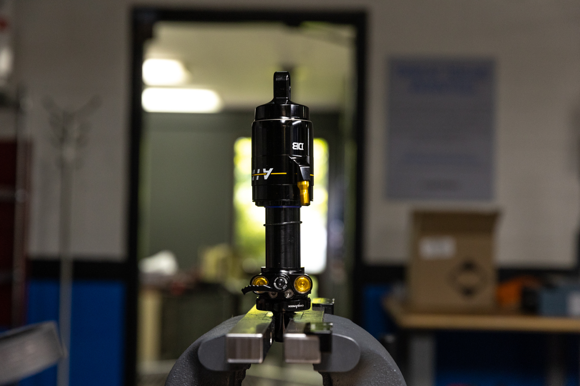
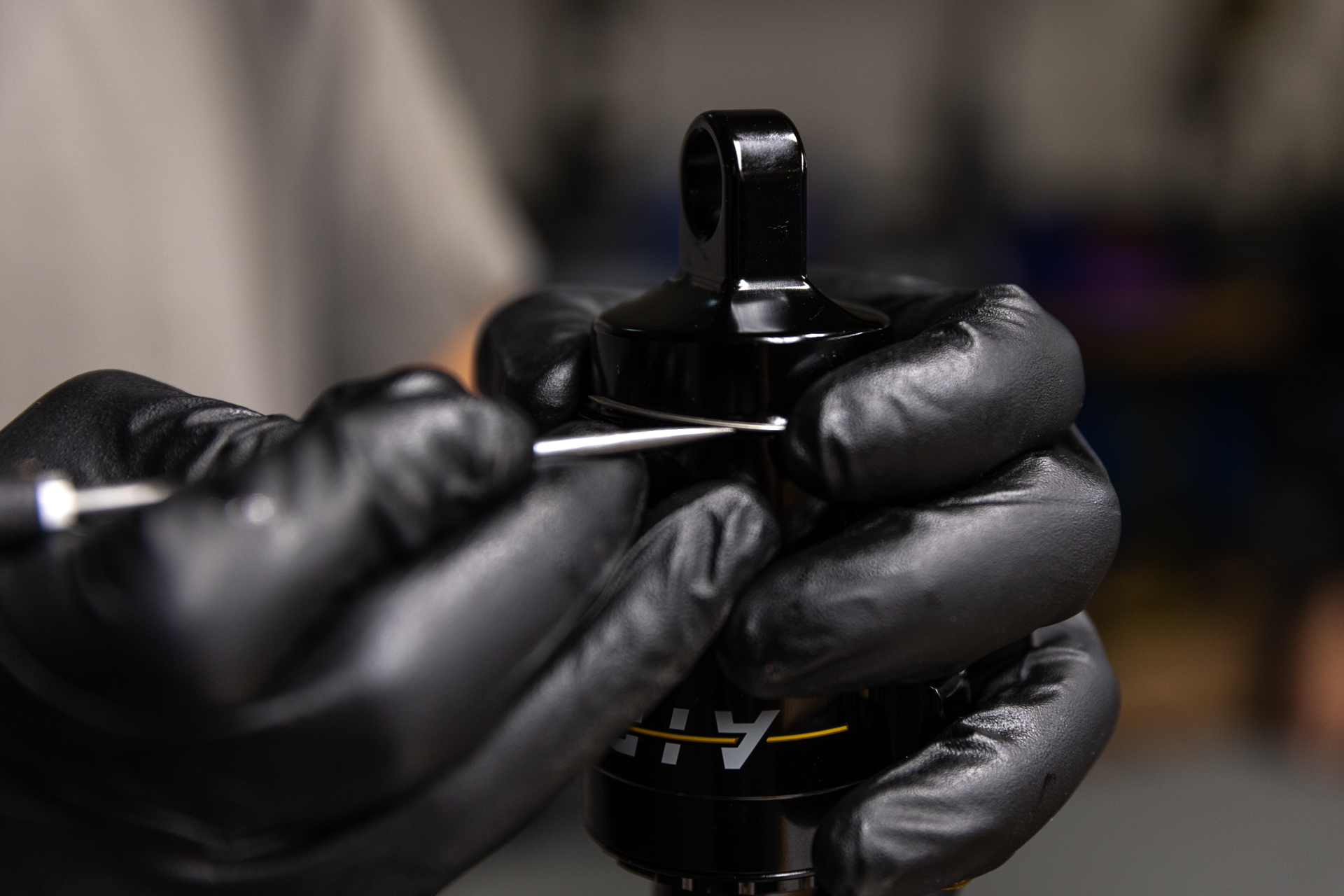
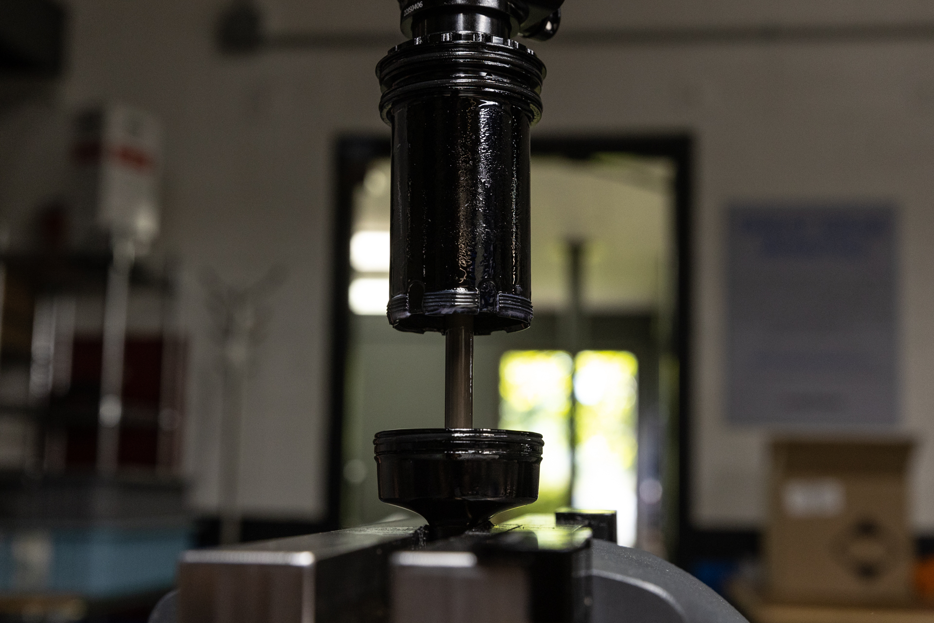
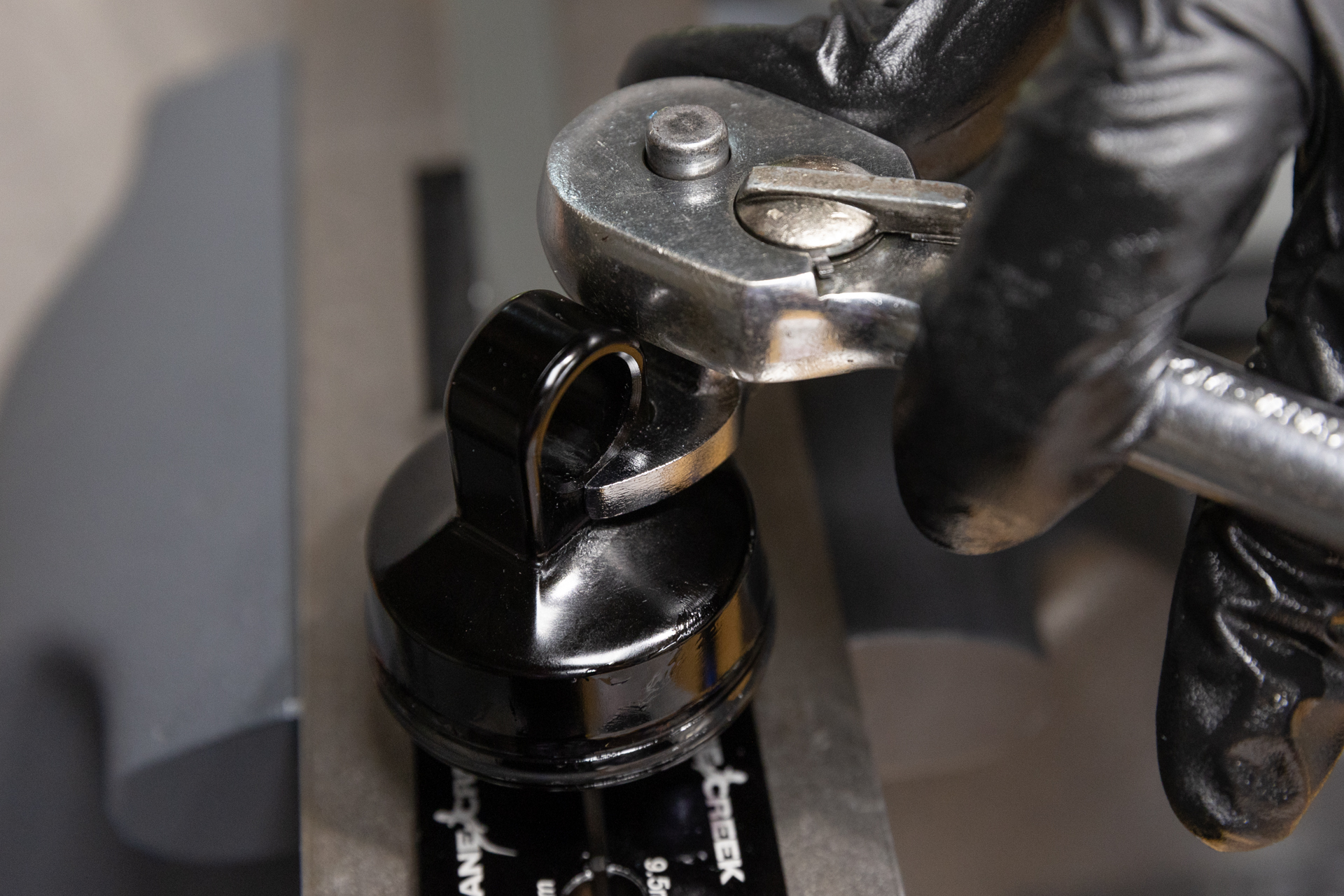
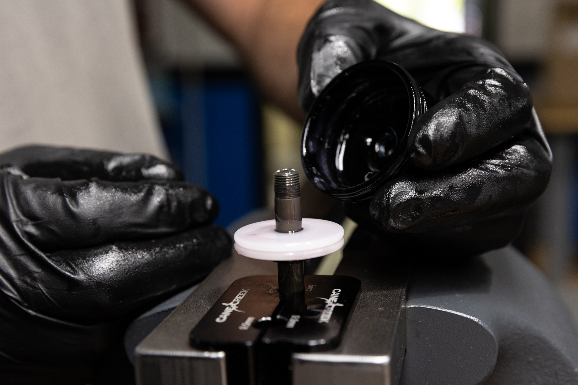
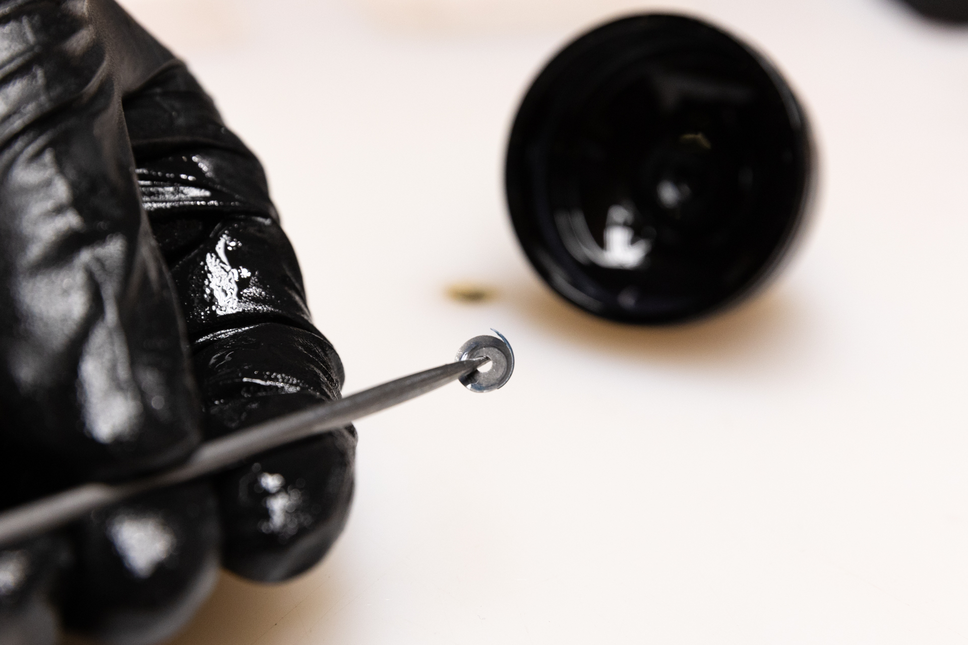
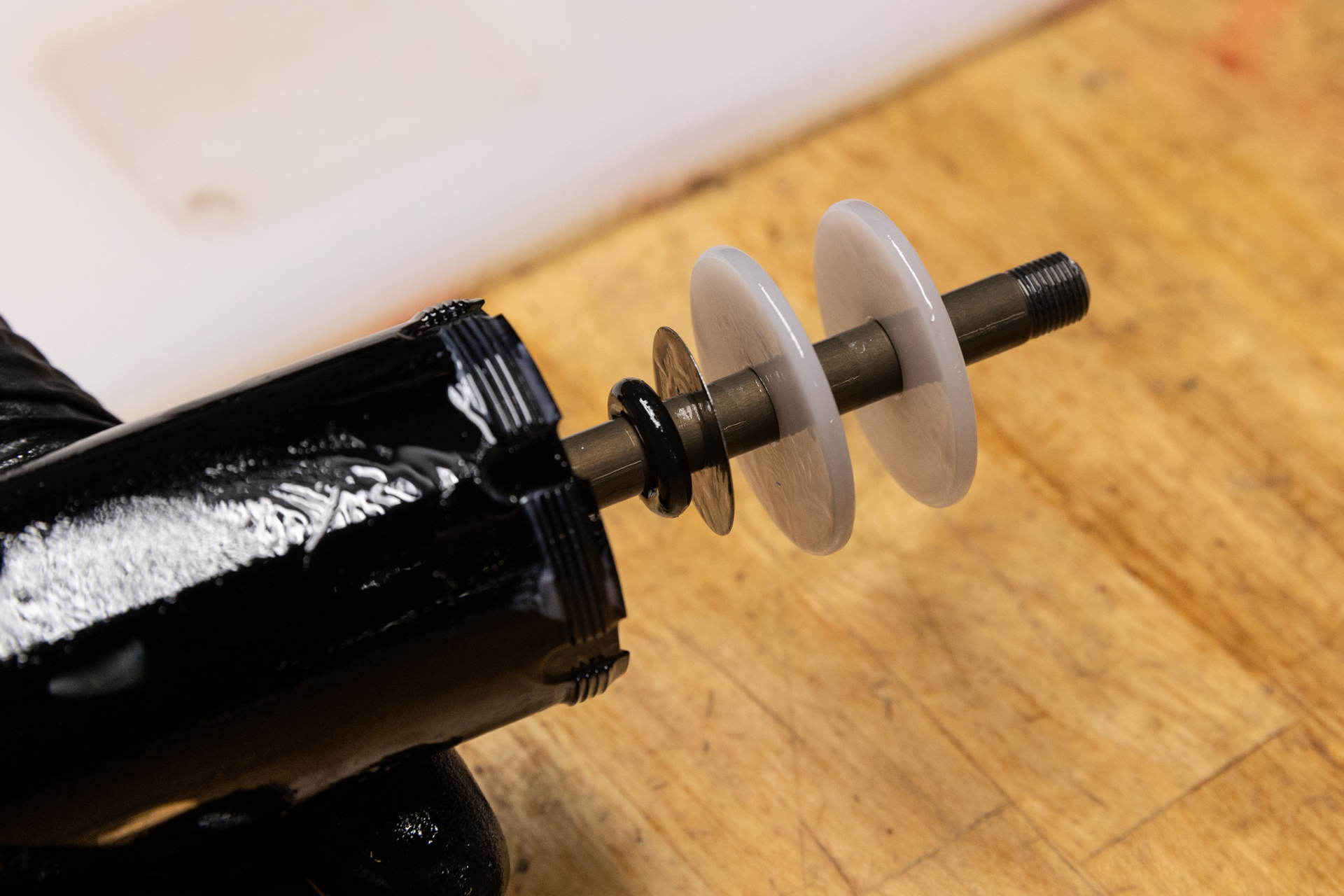
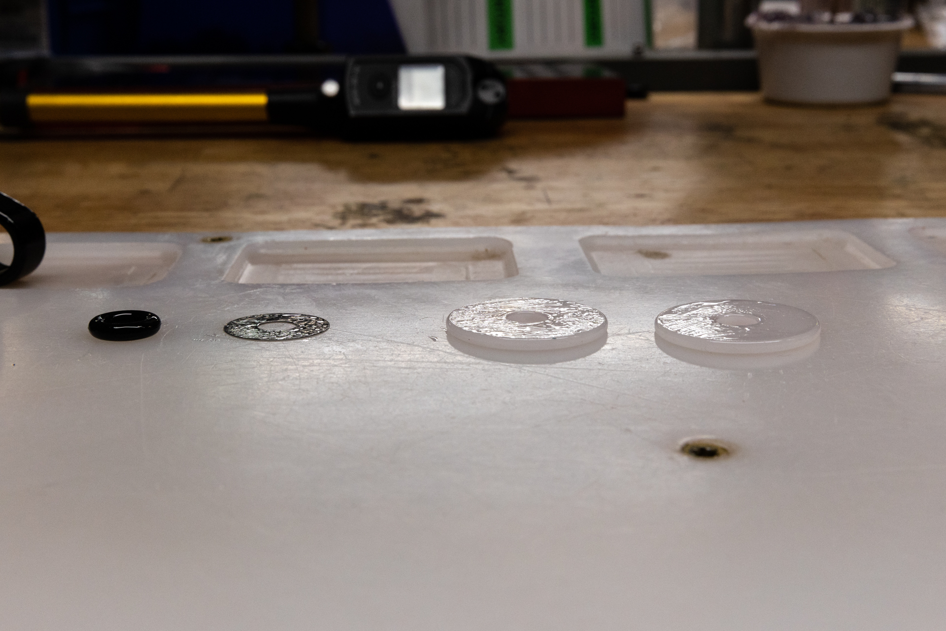
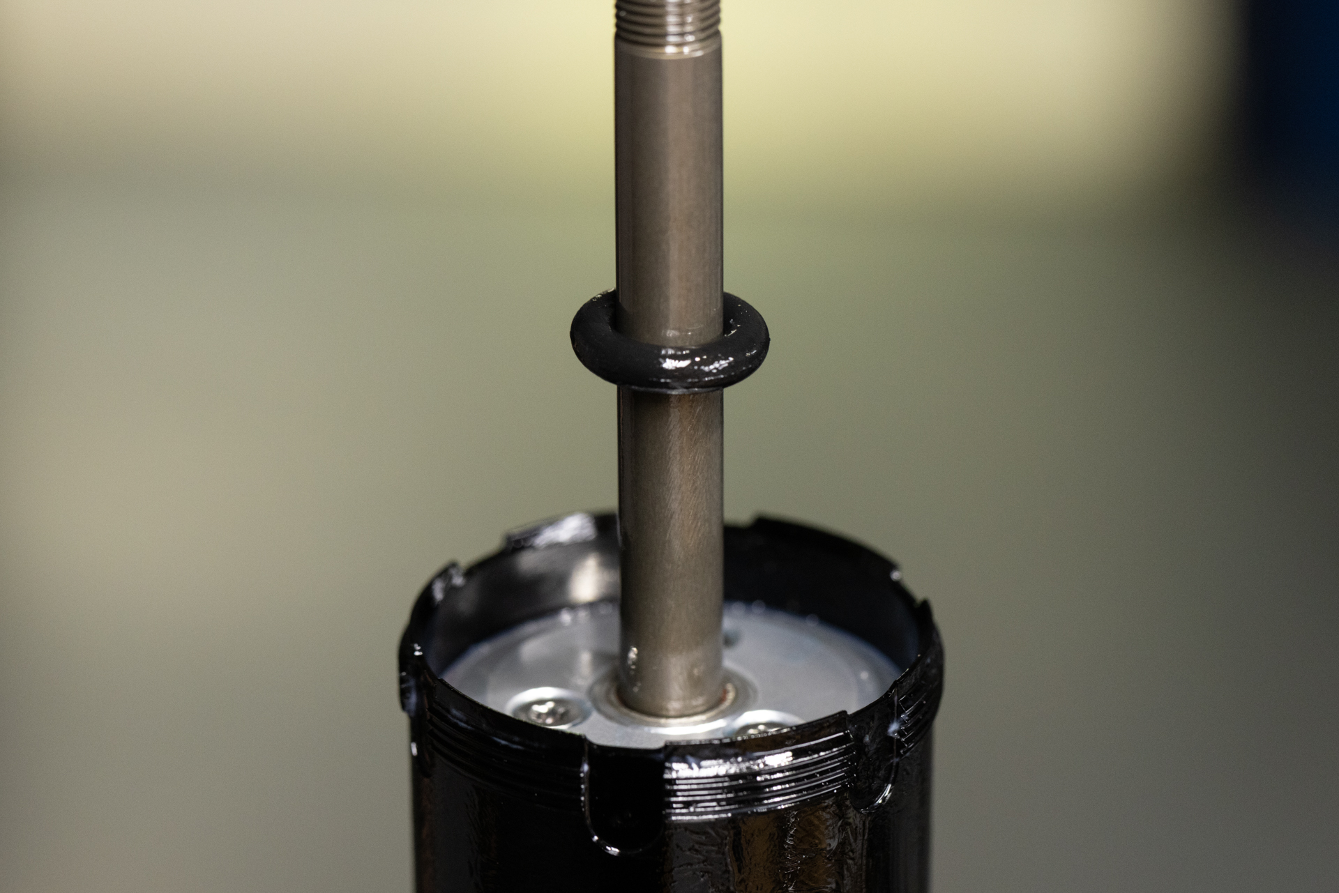
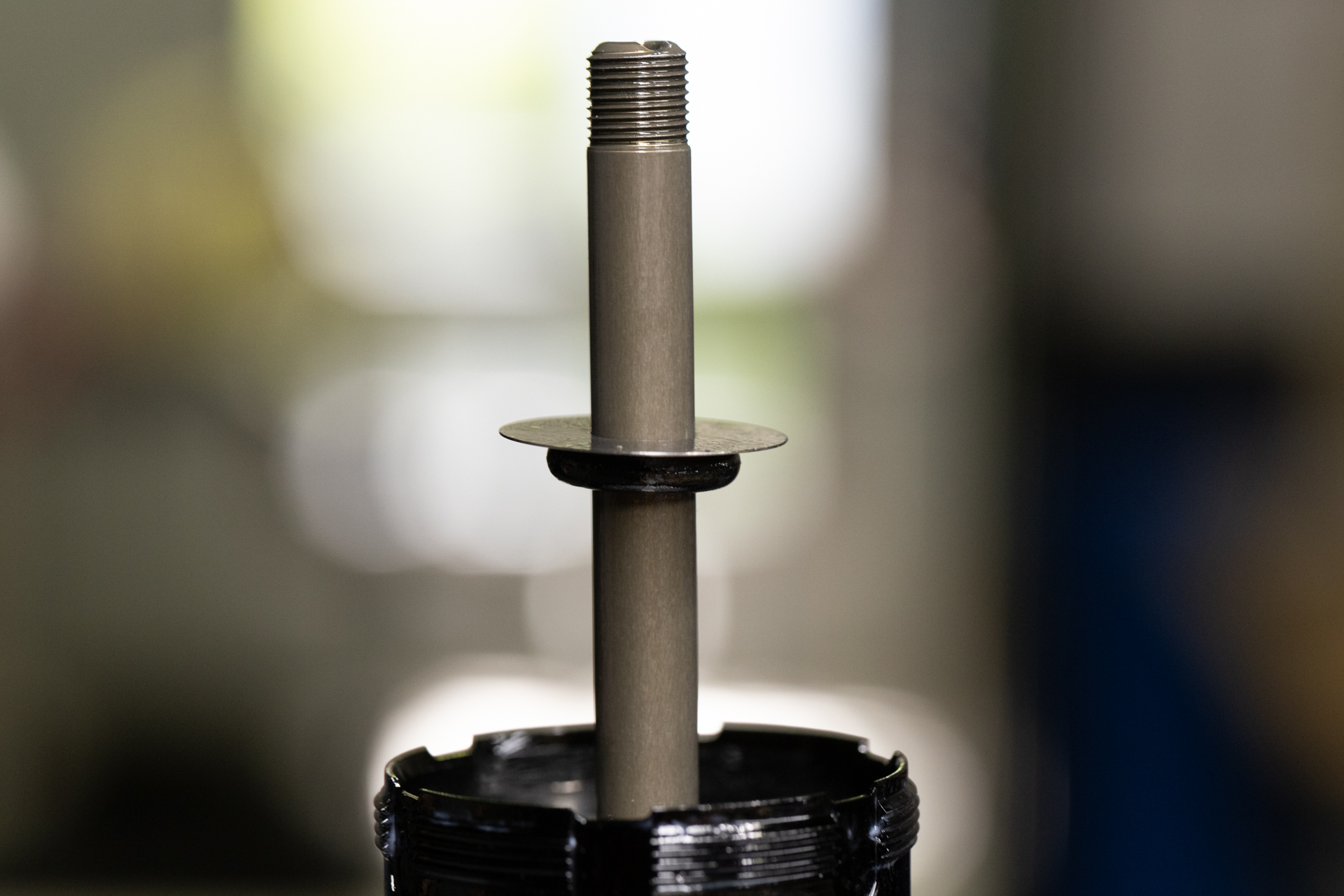
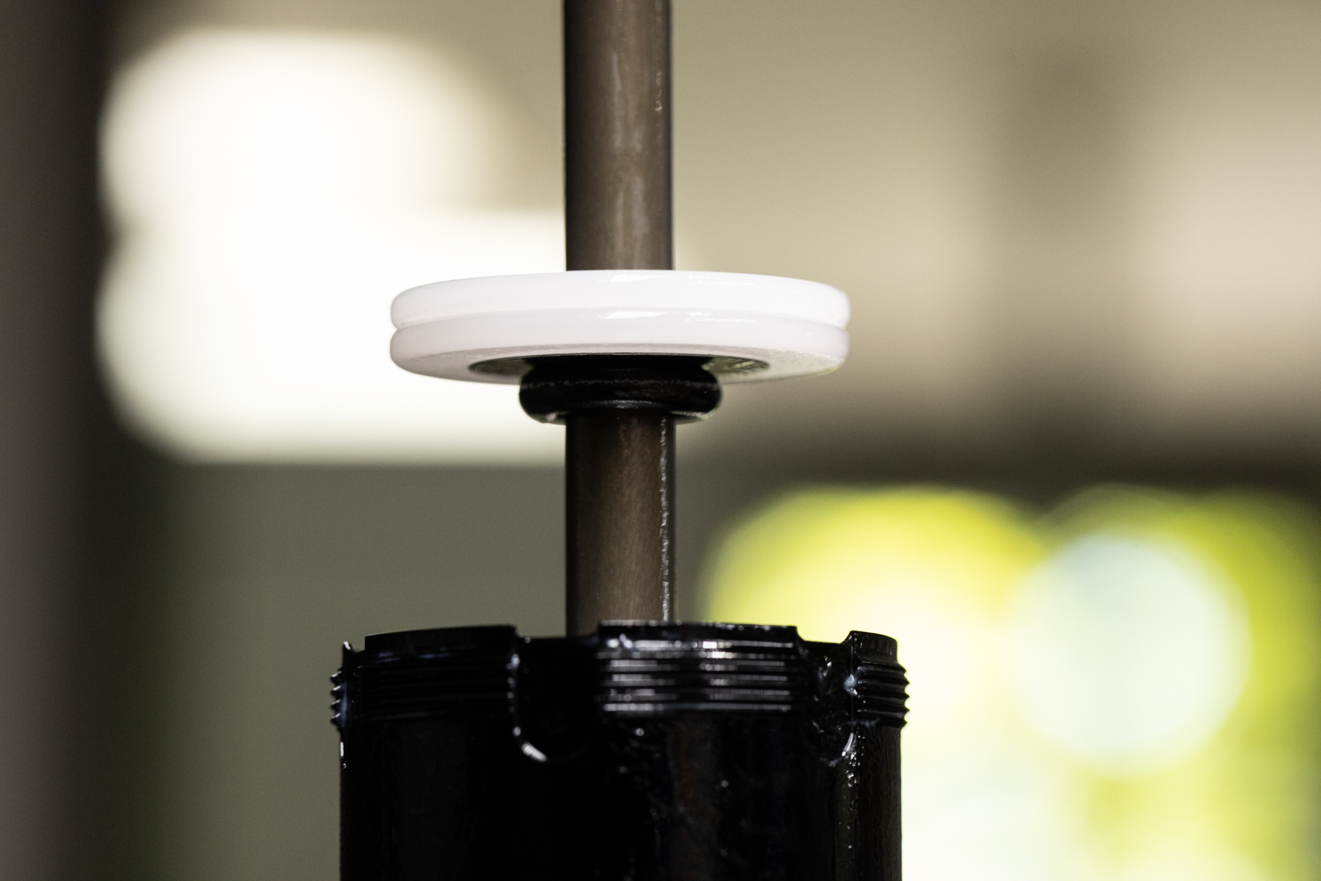
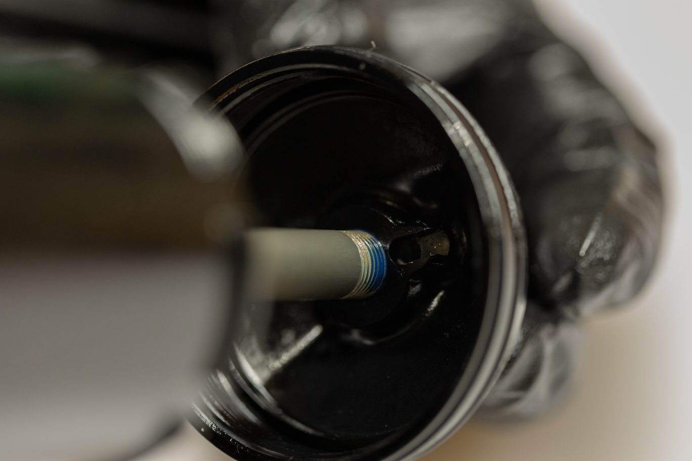
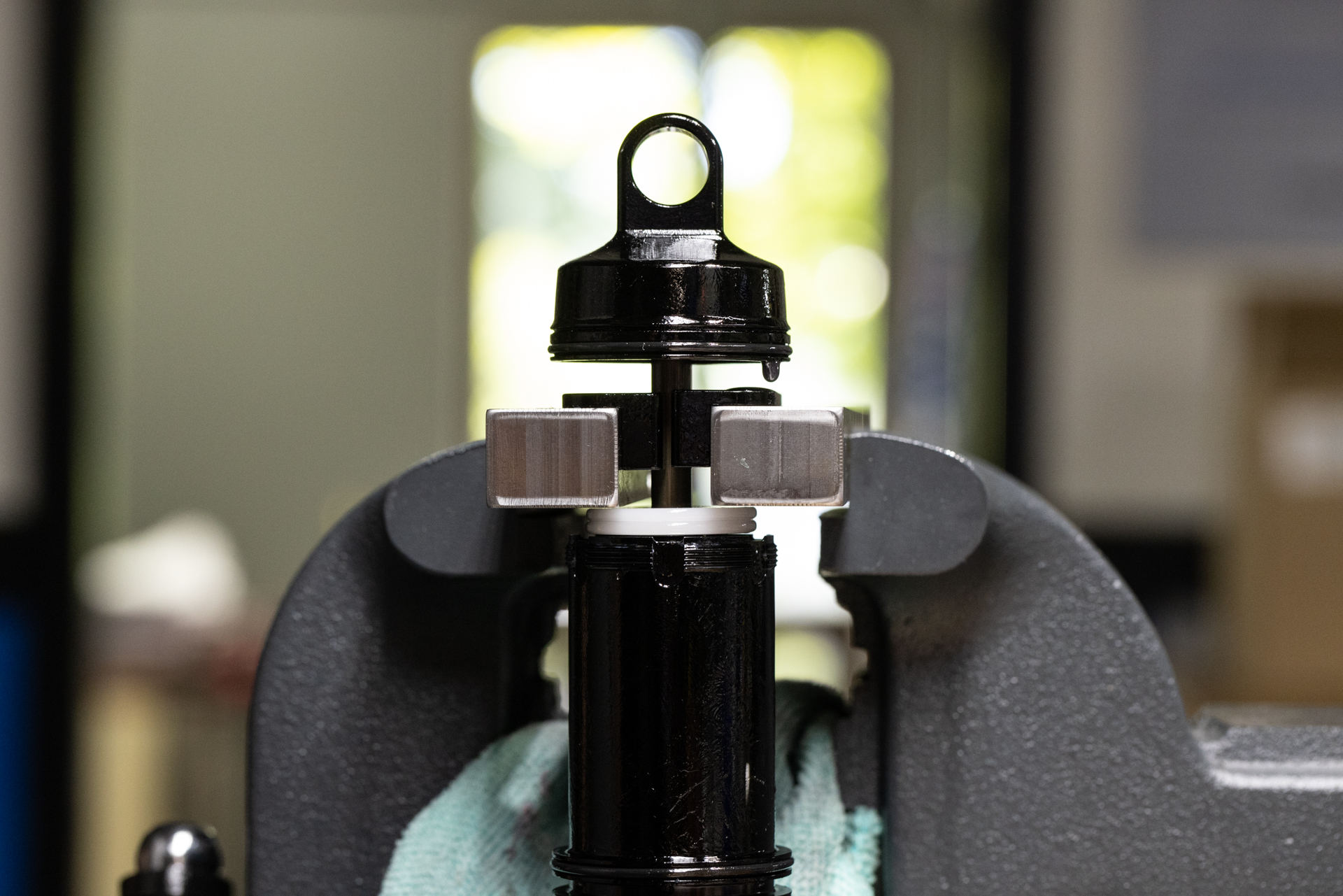
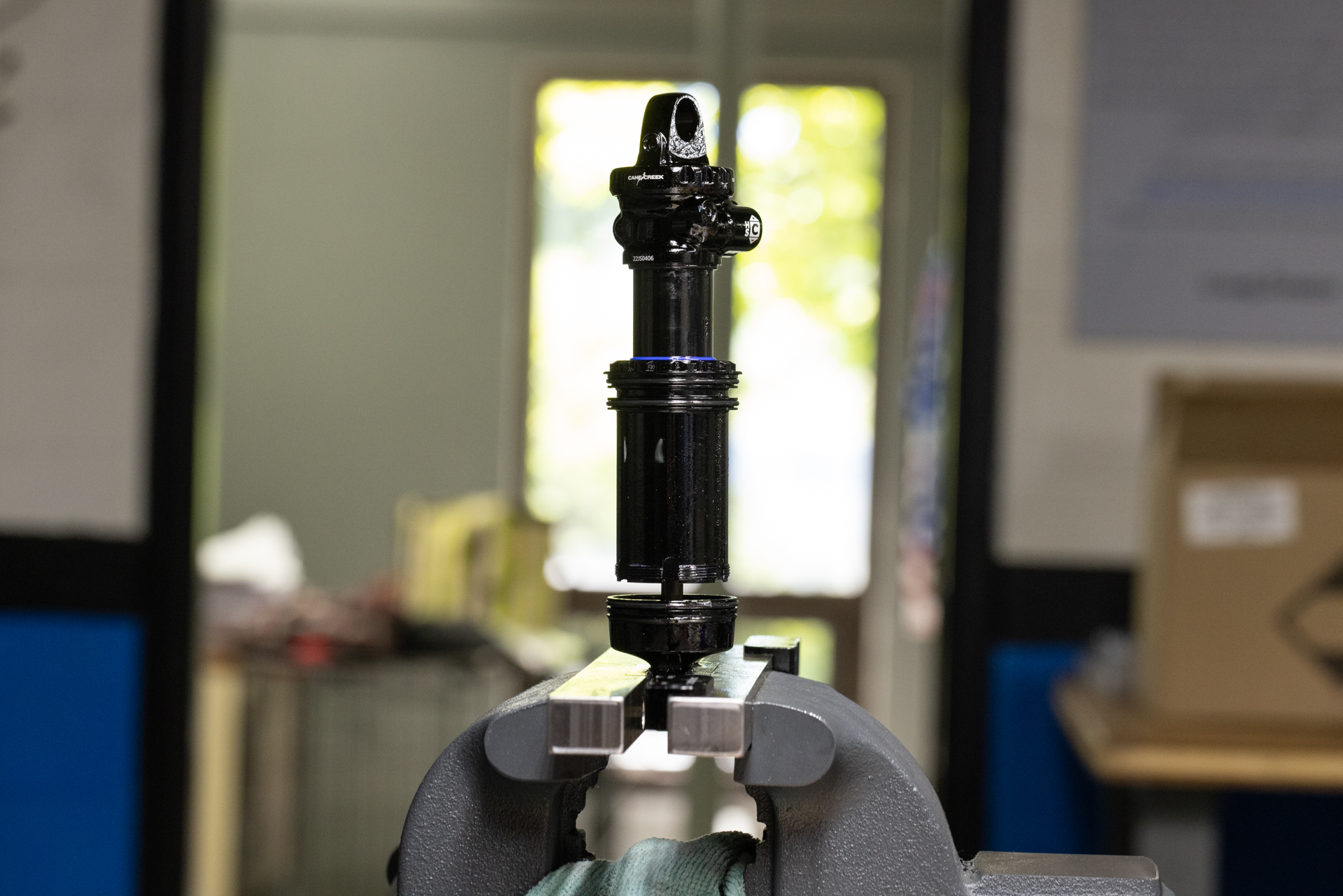
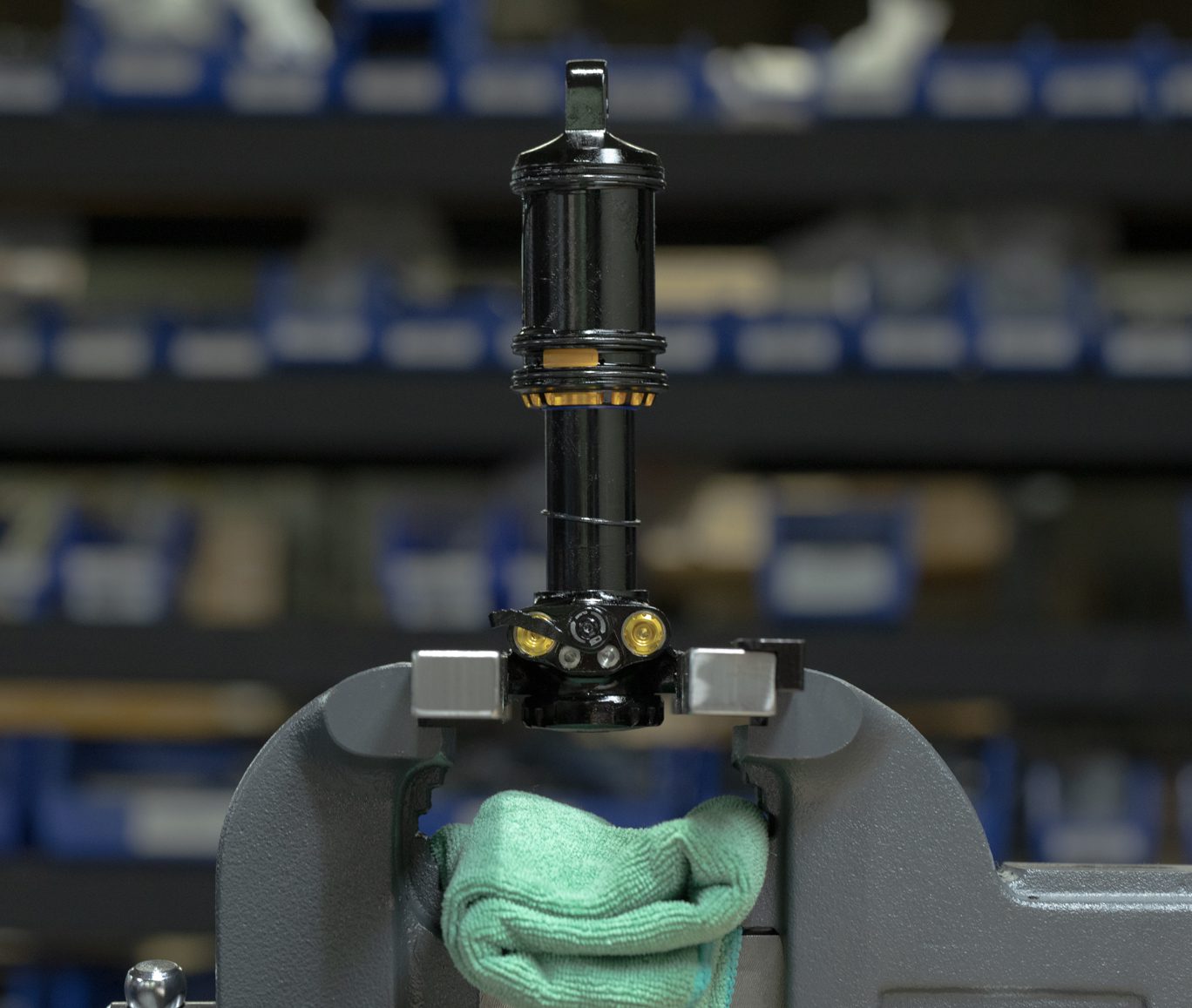
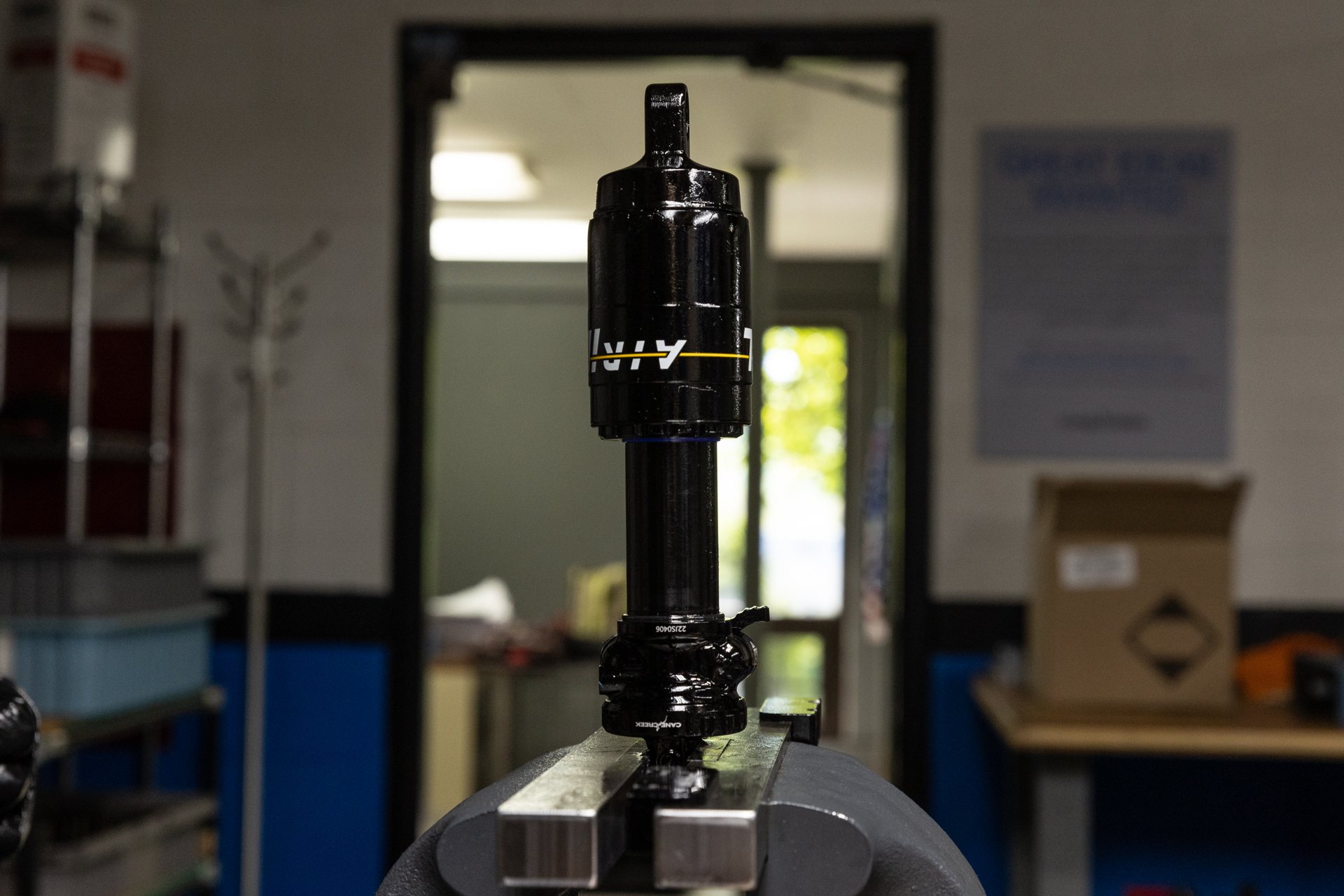
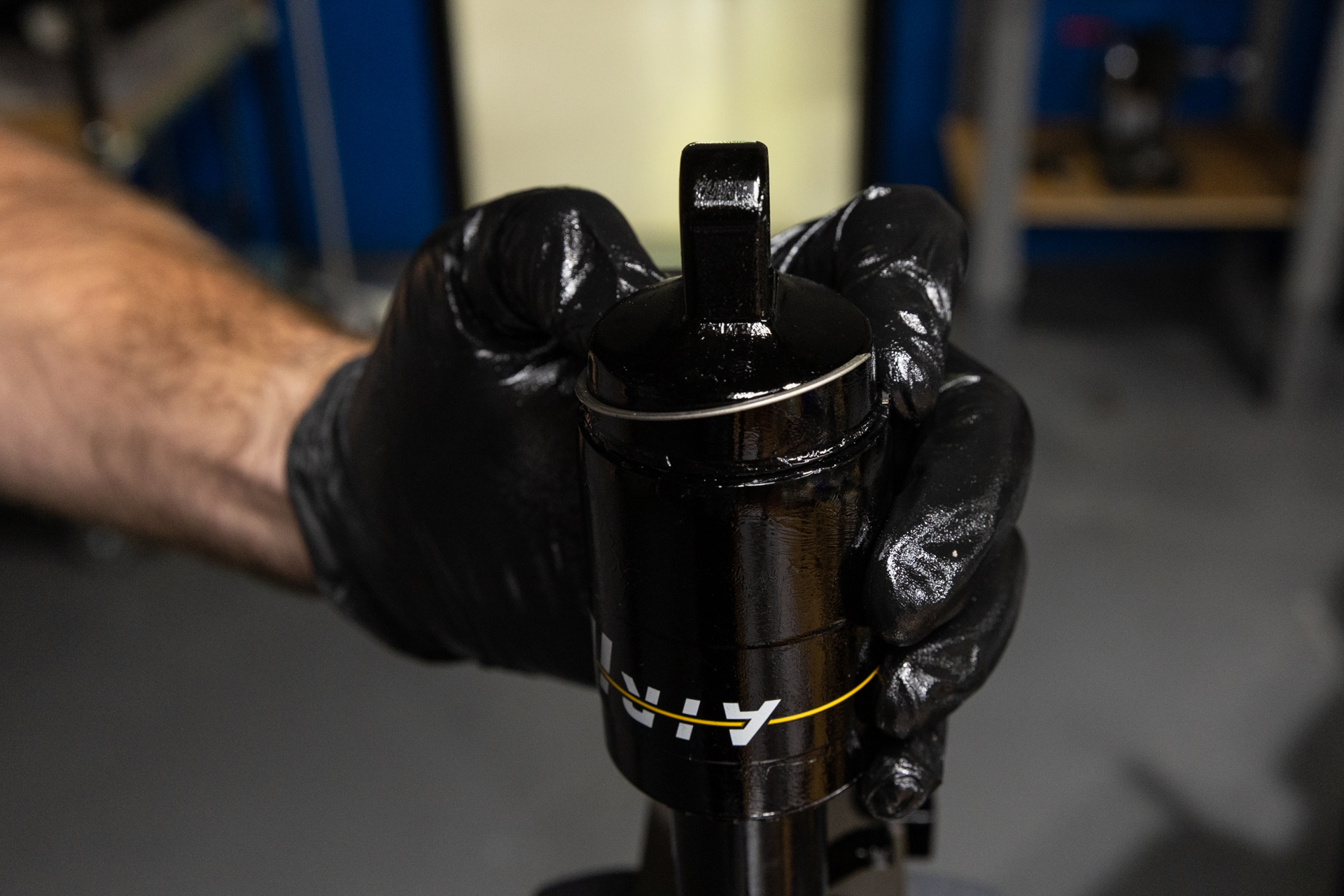
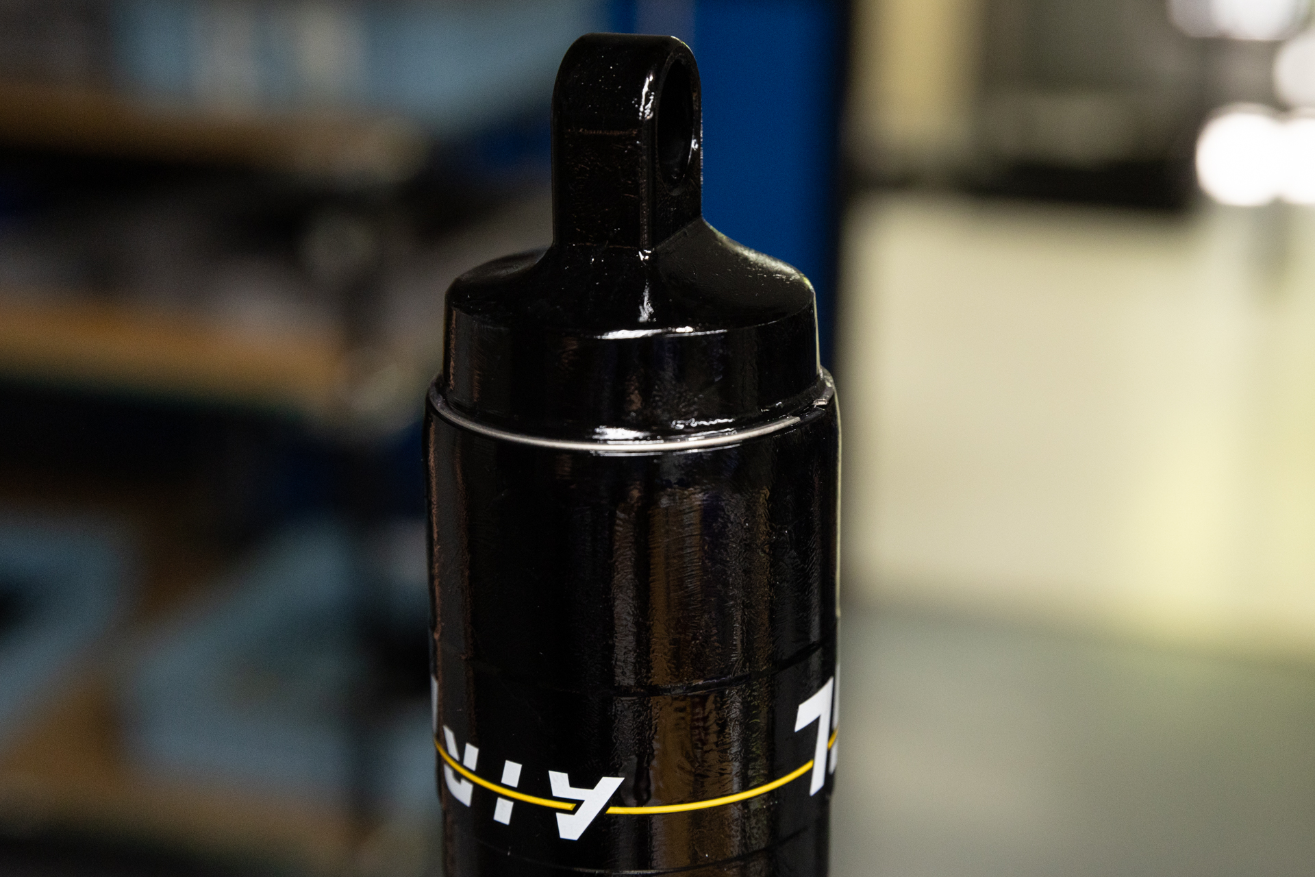
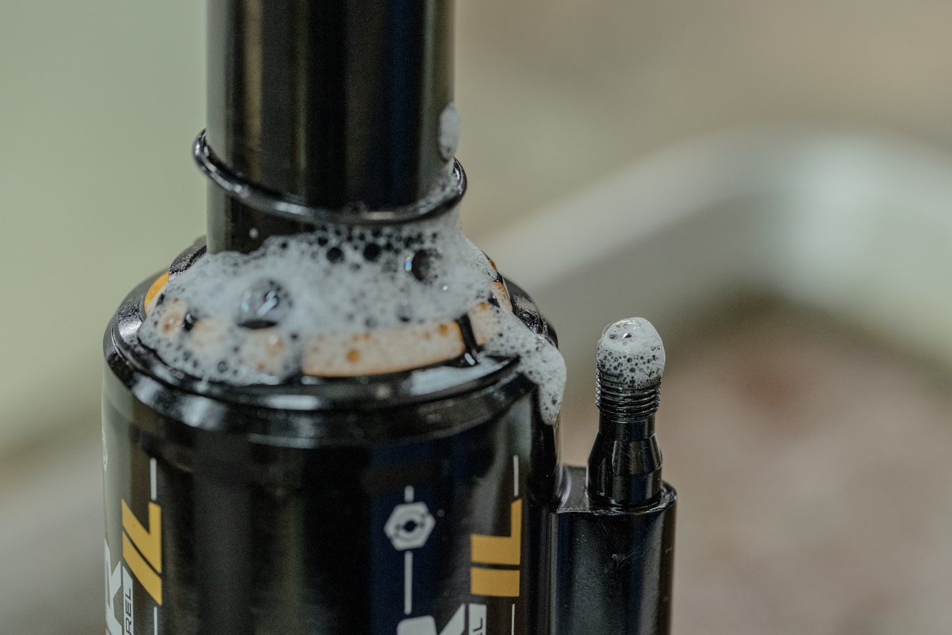
Slide inner air can up shock body to expose shaft. Clamp shaft in 8mm shaft clamp with end eye up. Remove end eye using 1/2″ crows foot. Pinch & remove then discard inner can o-ring and stop shim from end eye. Remove any stroke reduction spacer, shim and bottom out bumper.
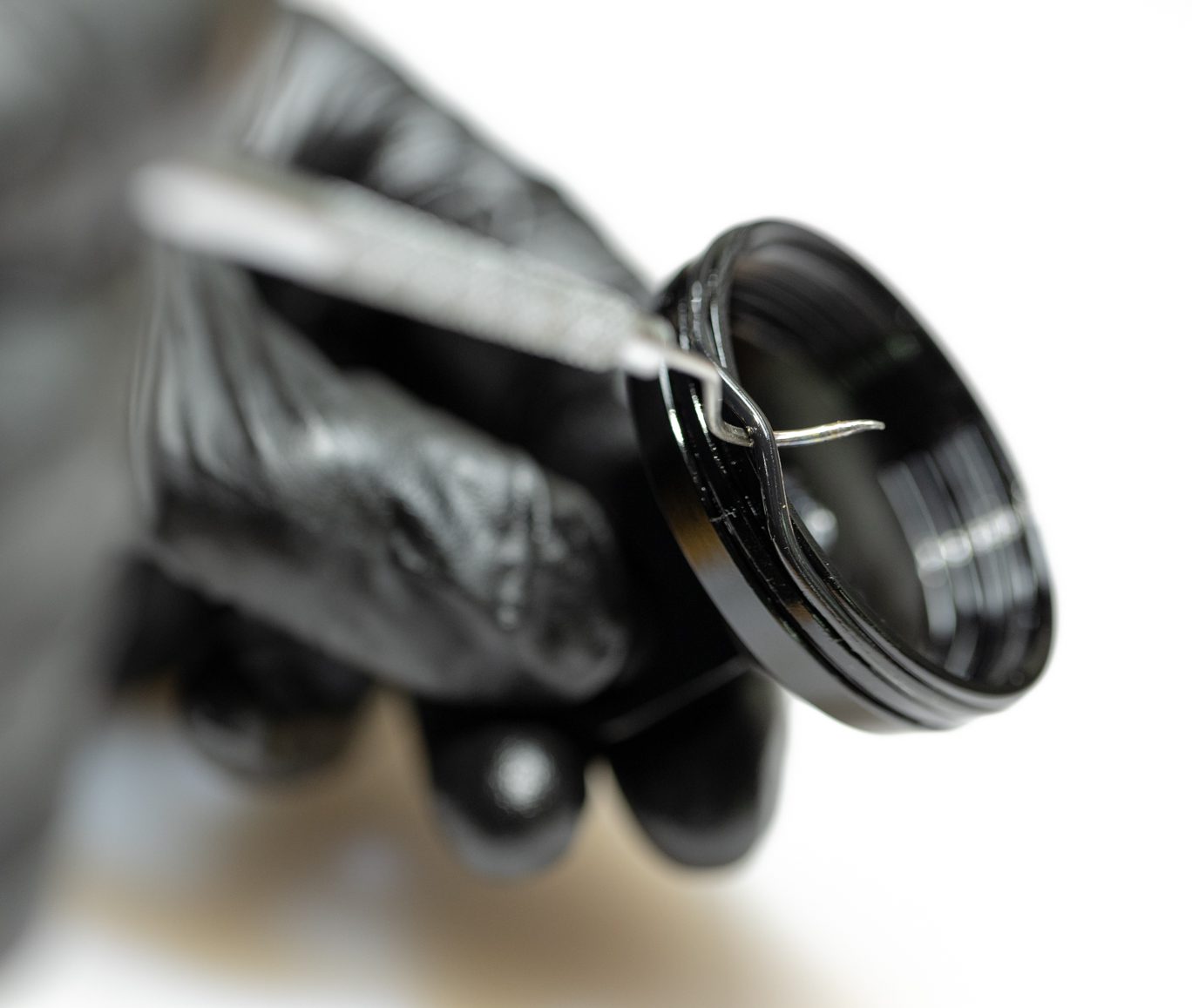
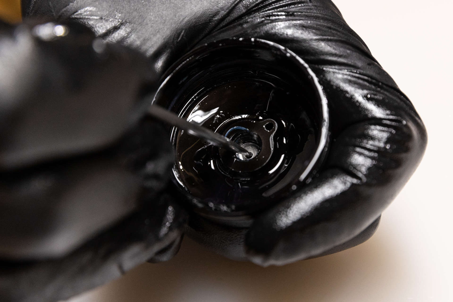
Always use extreme caution when using a pick in this step or others to avoid scratching metal parts. Failure to do this can create scratches in the o-ring glands which cause leak paths for oil or gas. When possible, pinch and remove o-rings rather than using a pick.
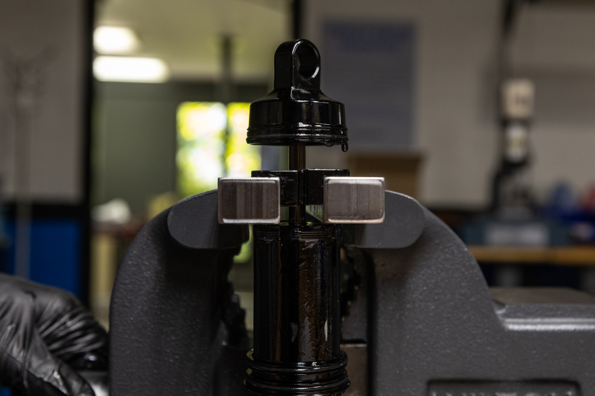
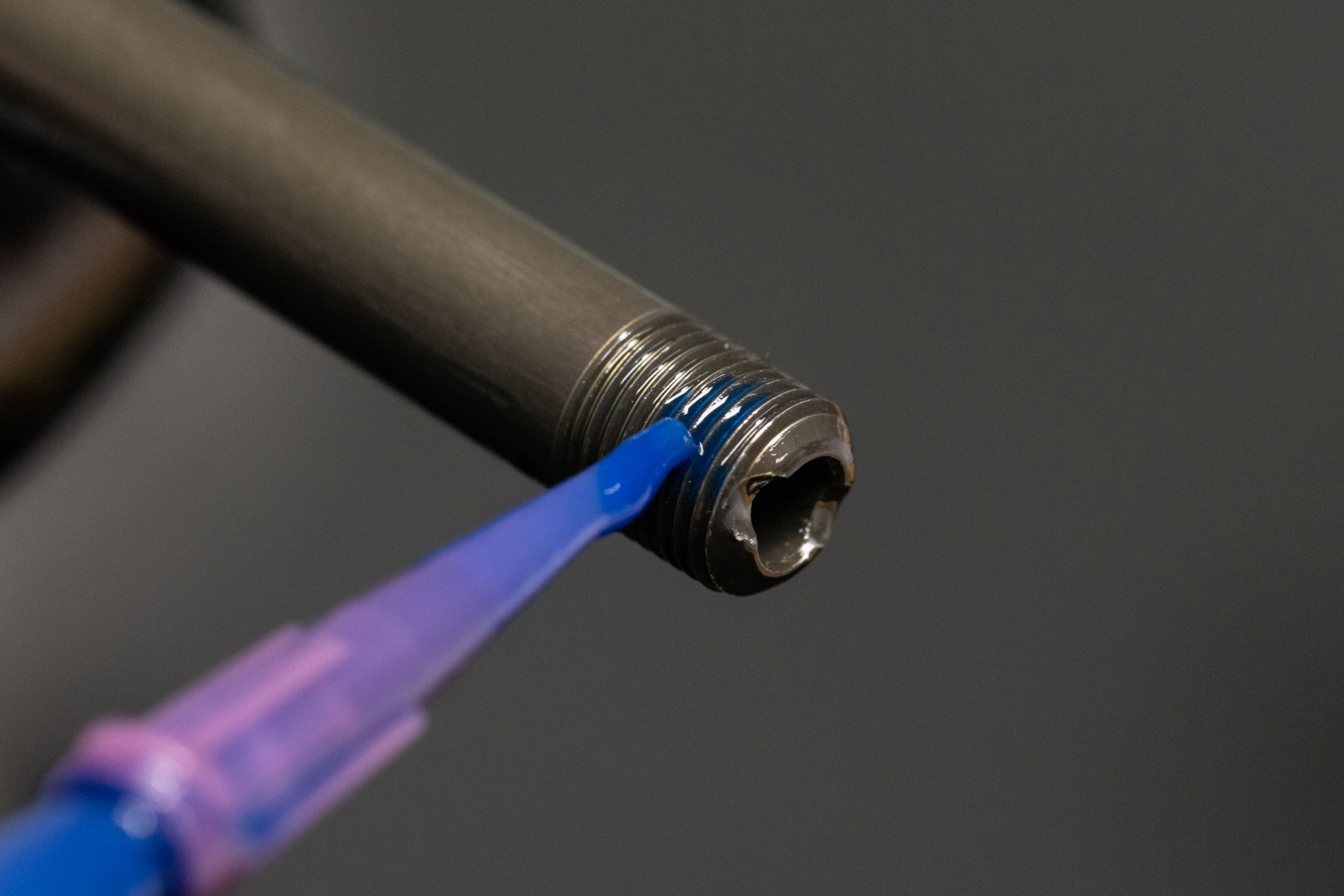
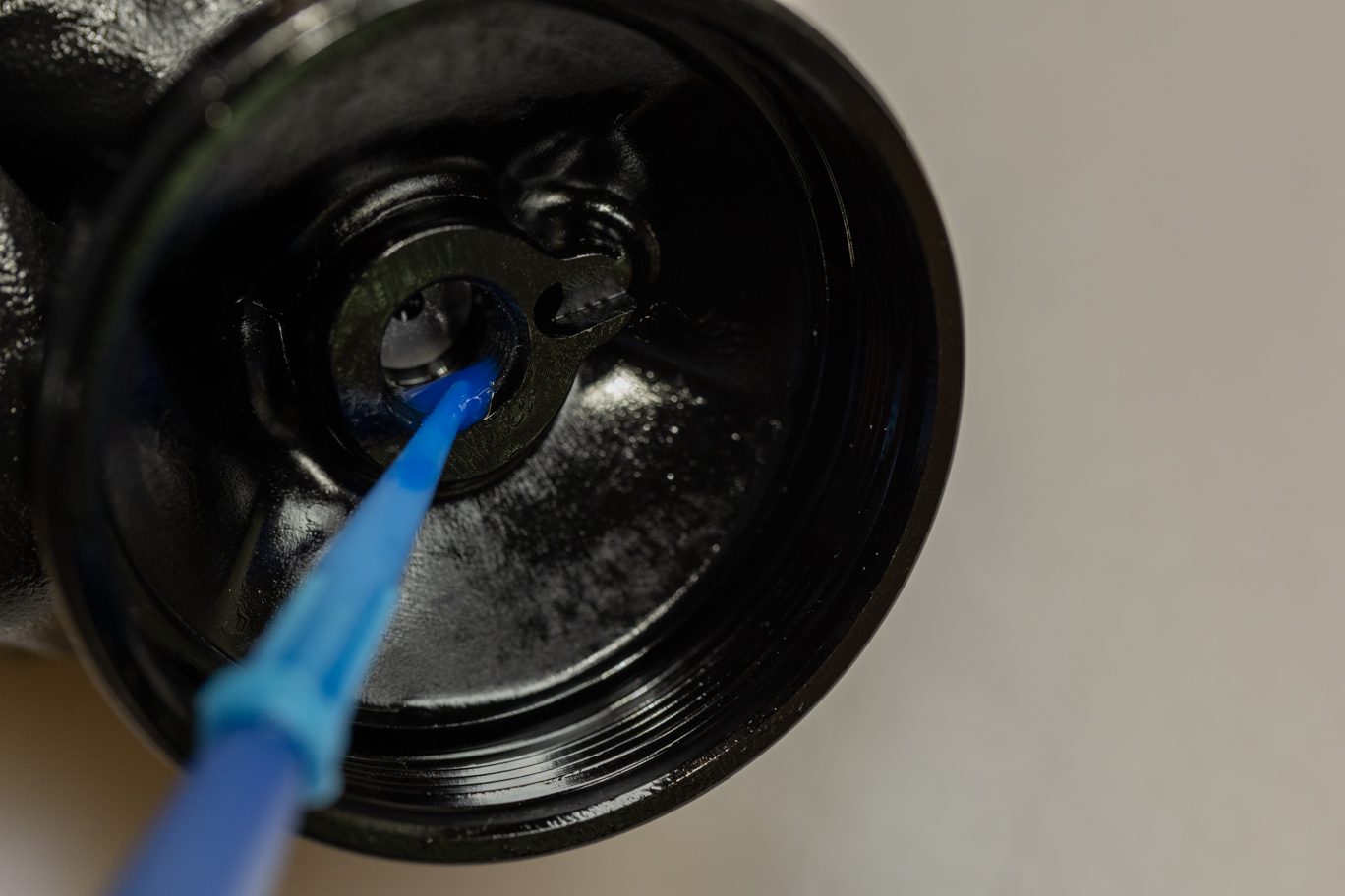
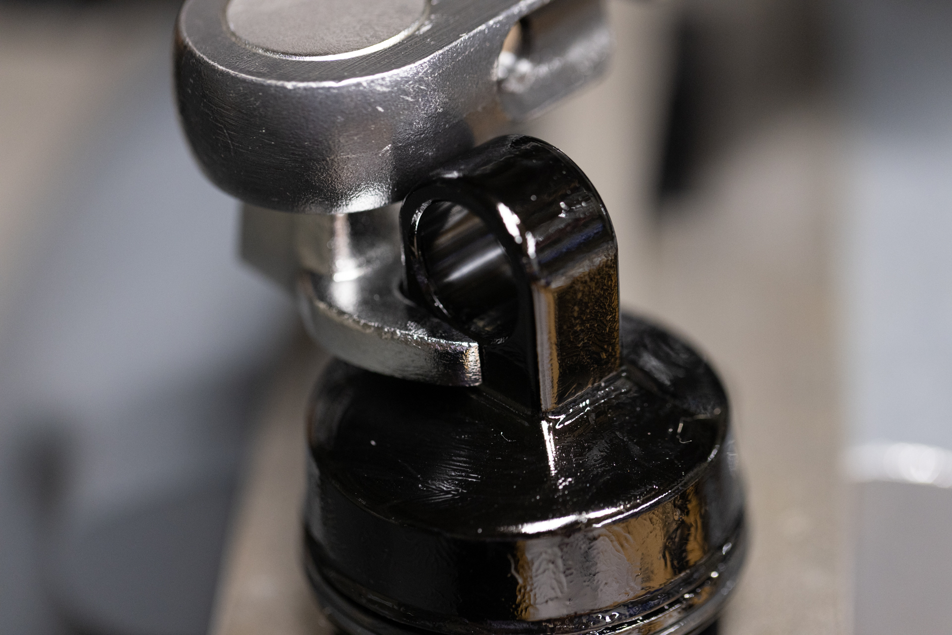
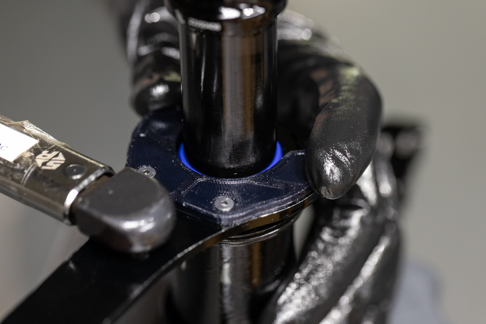
Reinstall bottom out bumper, shim and stroke reduction (if needed). Apply blue Loctite (243) to shaft threads and end eye threads. Thread end eye onto the shaft. Clamp shaft into vise with shaft clamp allowing space for end eye to clear vise when tightened. Using 1/2″ crowsfoot, torque end eye to 4.8 Nm. Clean any extra Loctite from shaft and end eye.
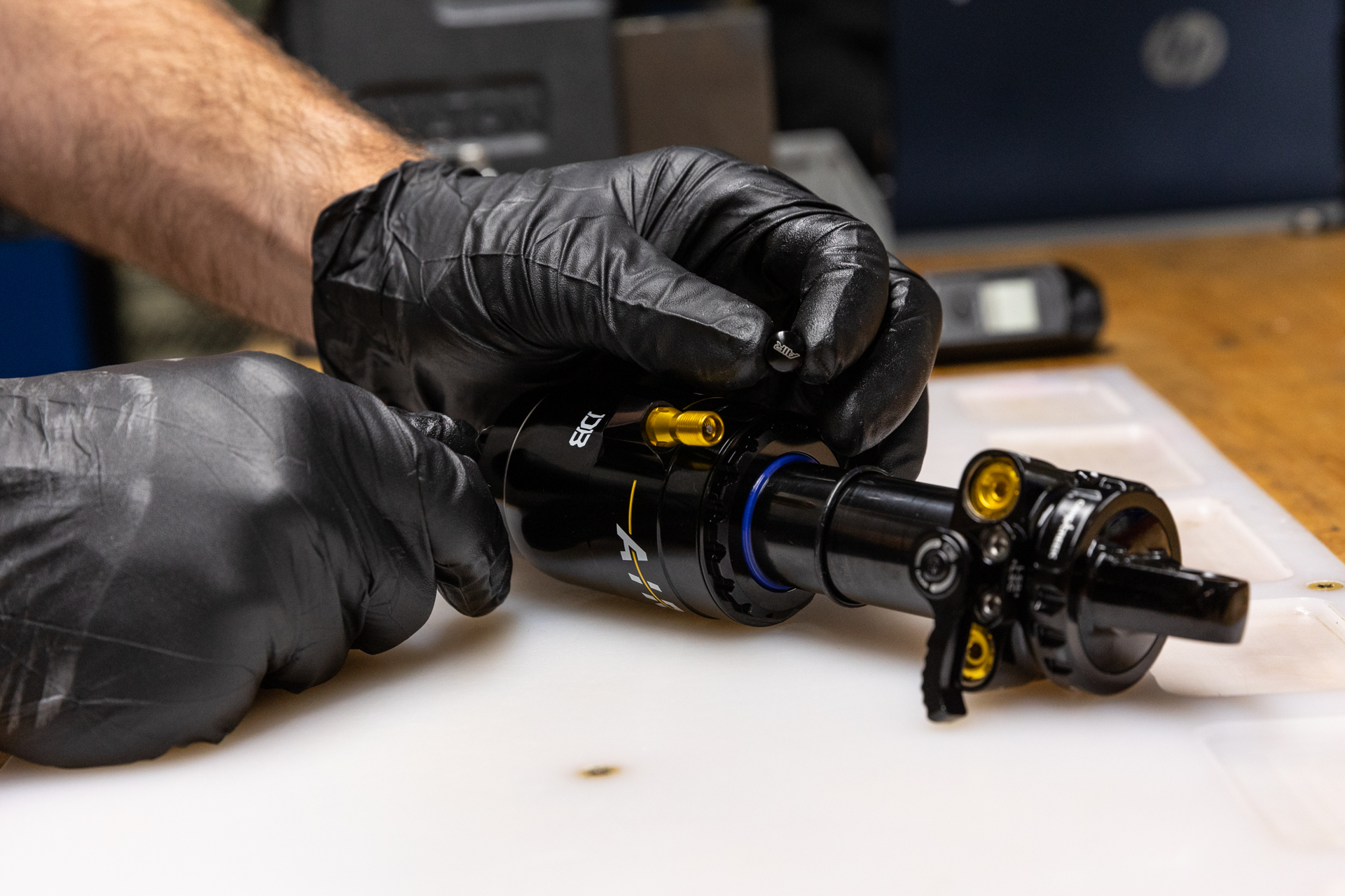
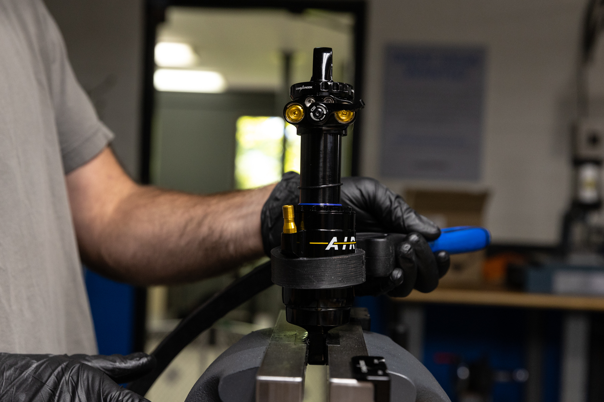
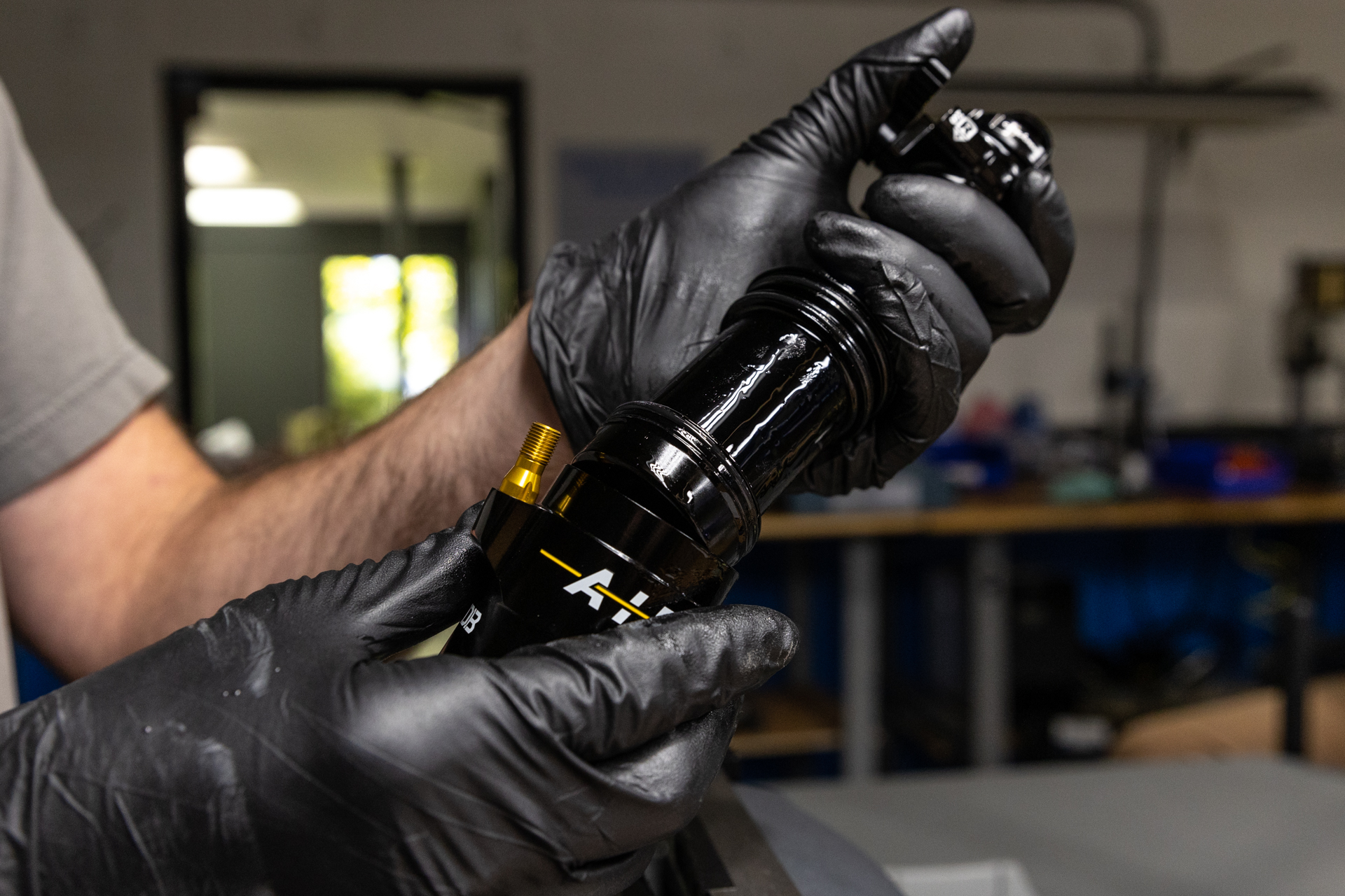
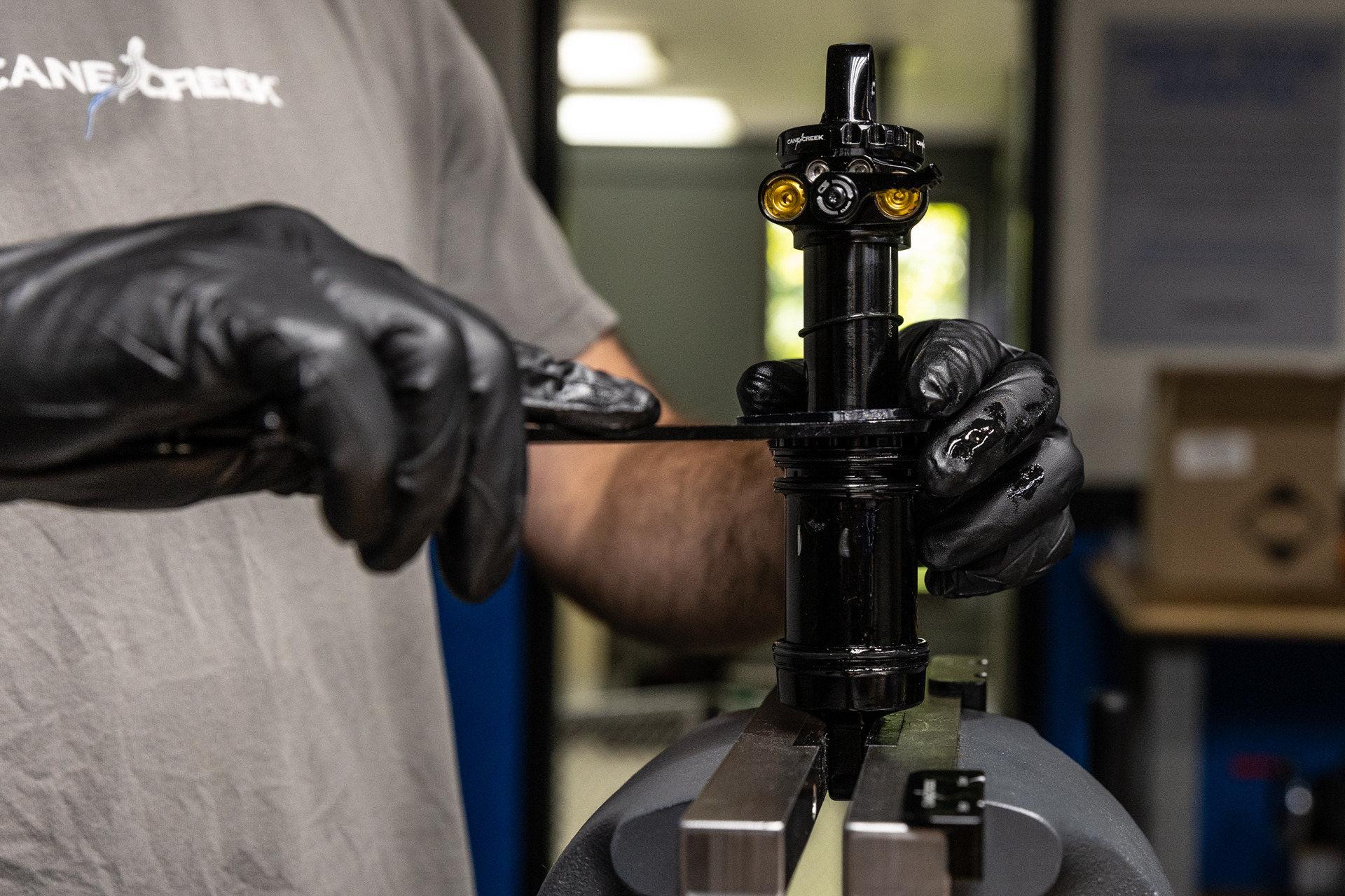
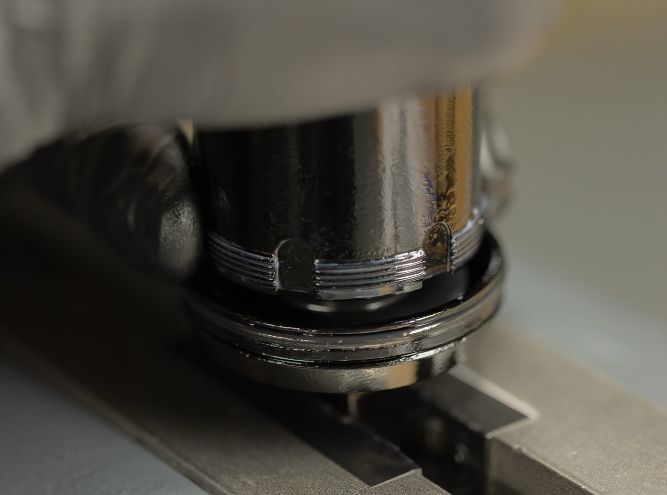
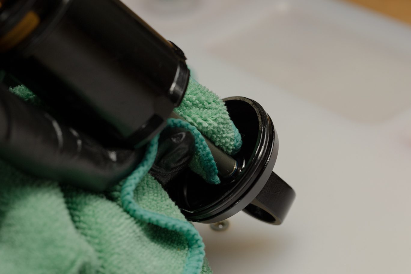
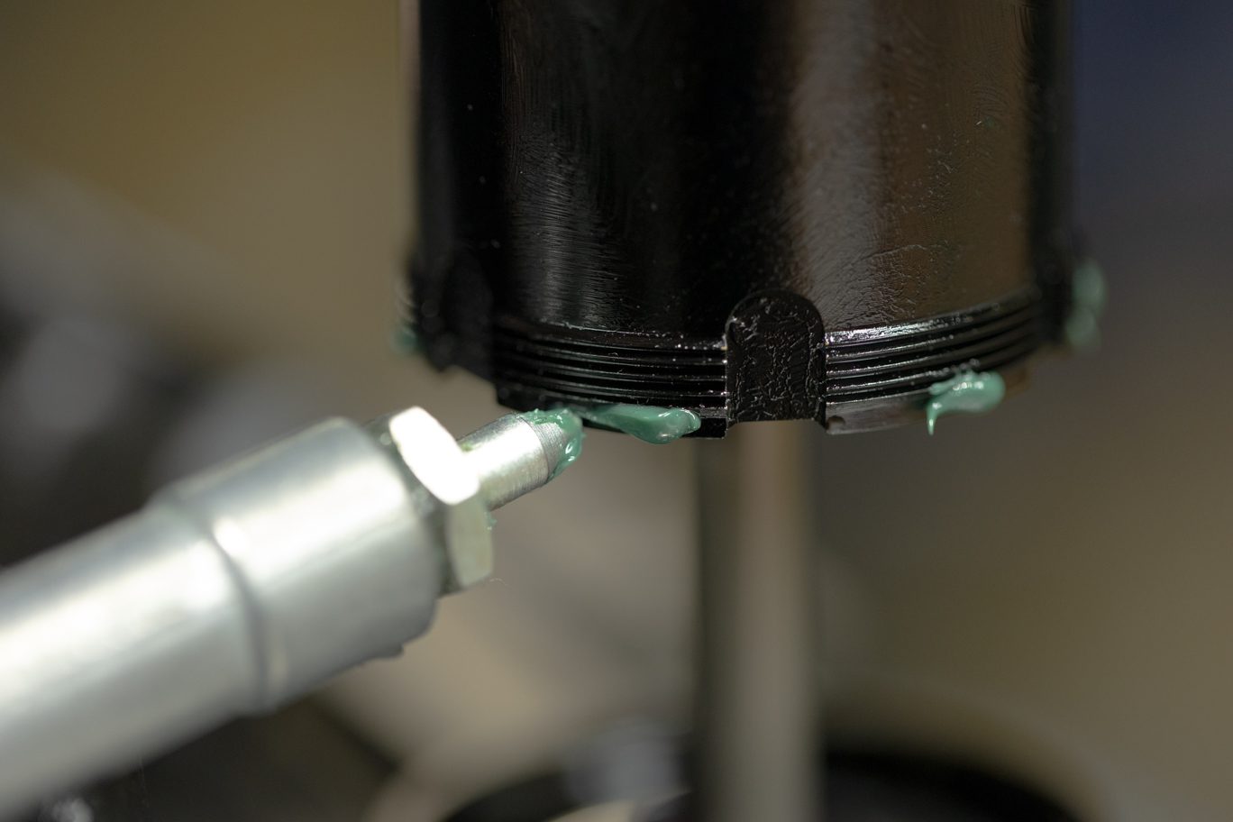
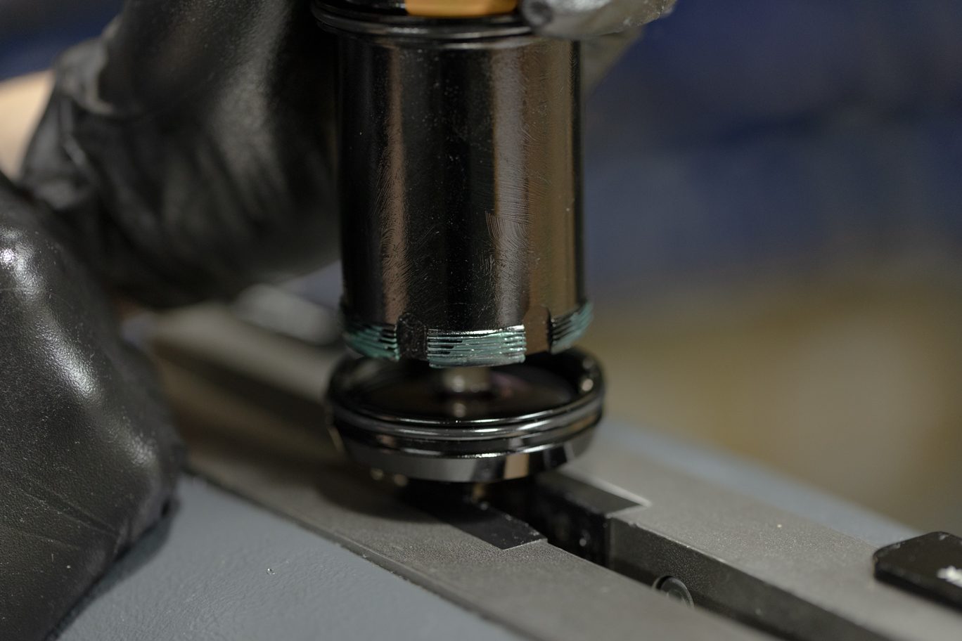
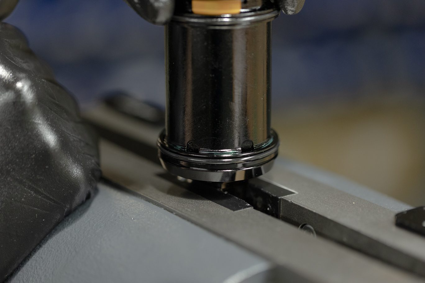
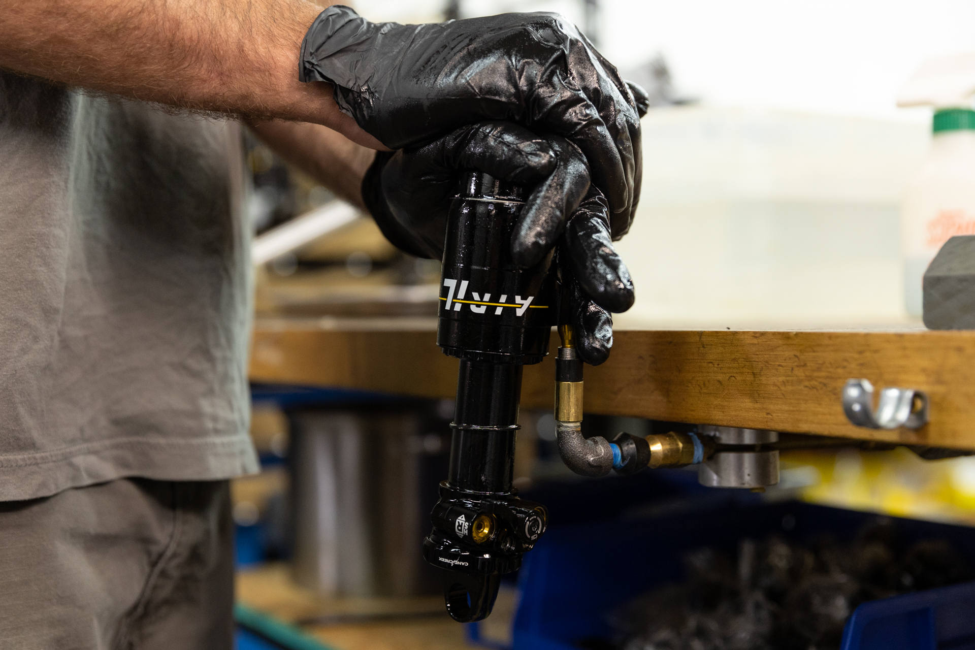
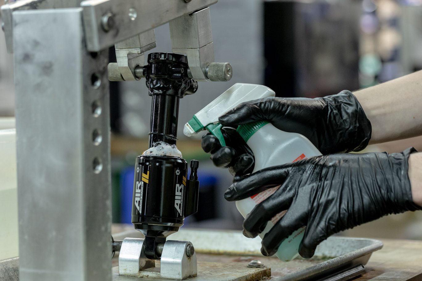
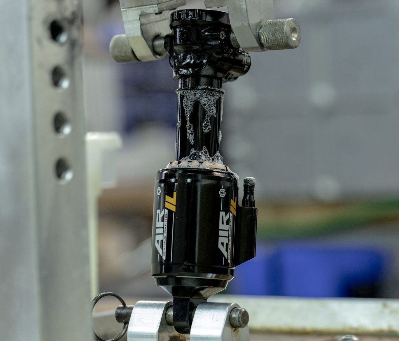
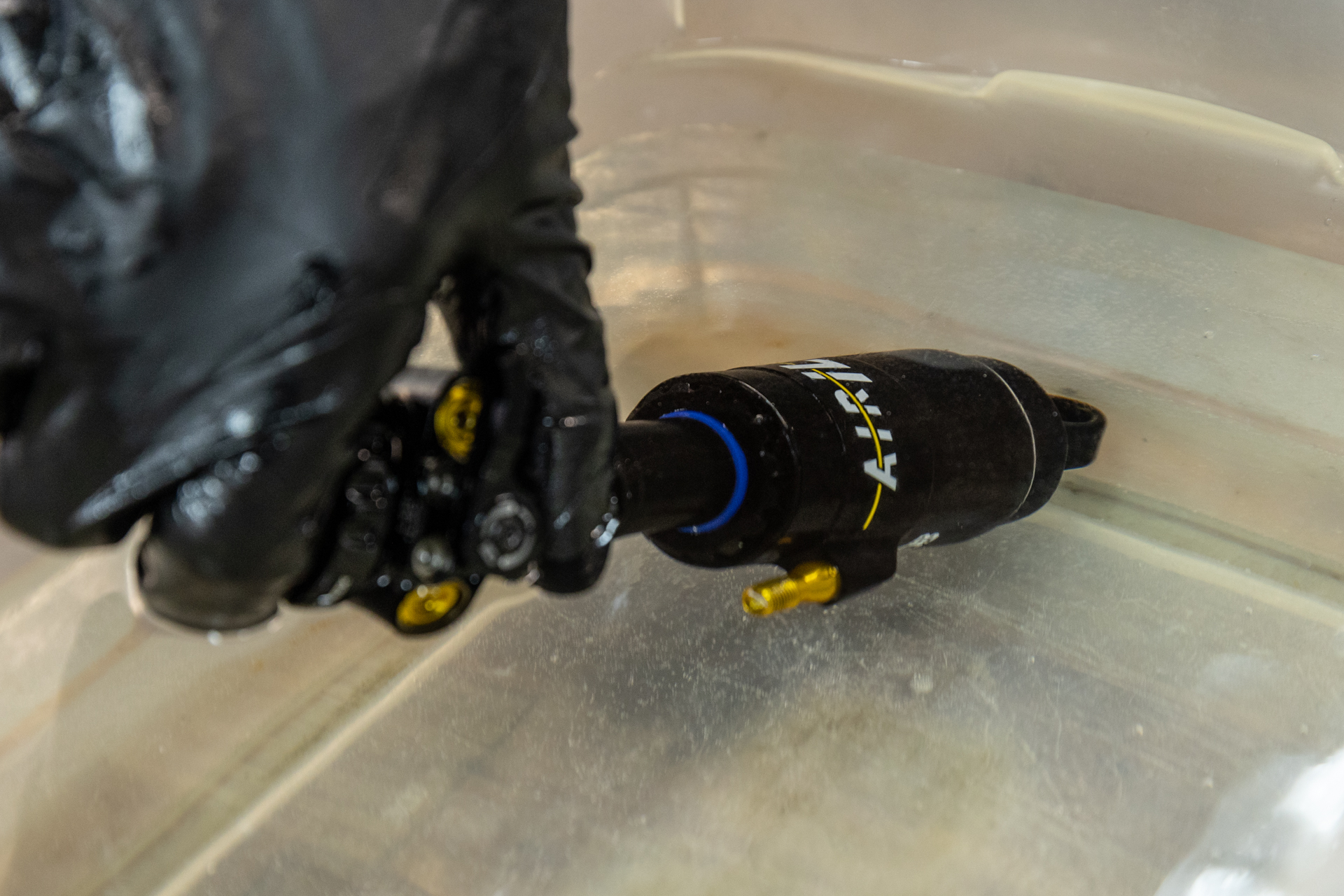
Clamp valve body end into vise. Work outer air can gently past o-rings. Note correct orientation of air can and reinstall any volume reduction. Final o-ring will be tight. Strap wrench may be necessary. Engage Climb Switch to aid installation. Ensure valve is oriented away from Climb Switch. Install outer air can retention clip.
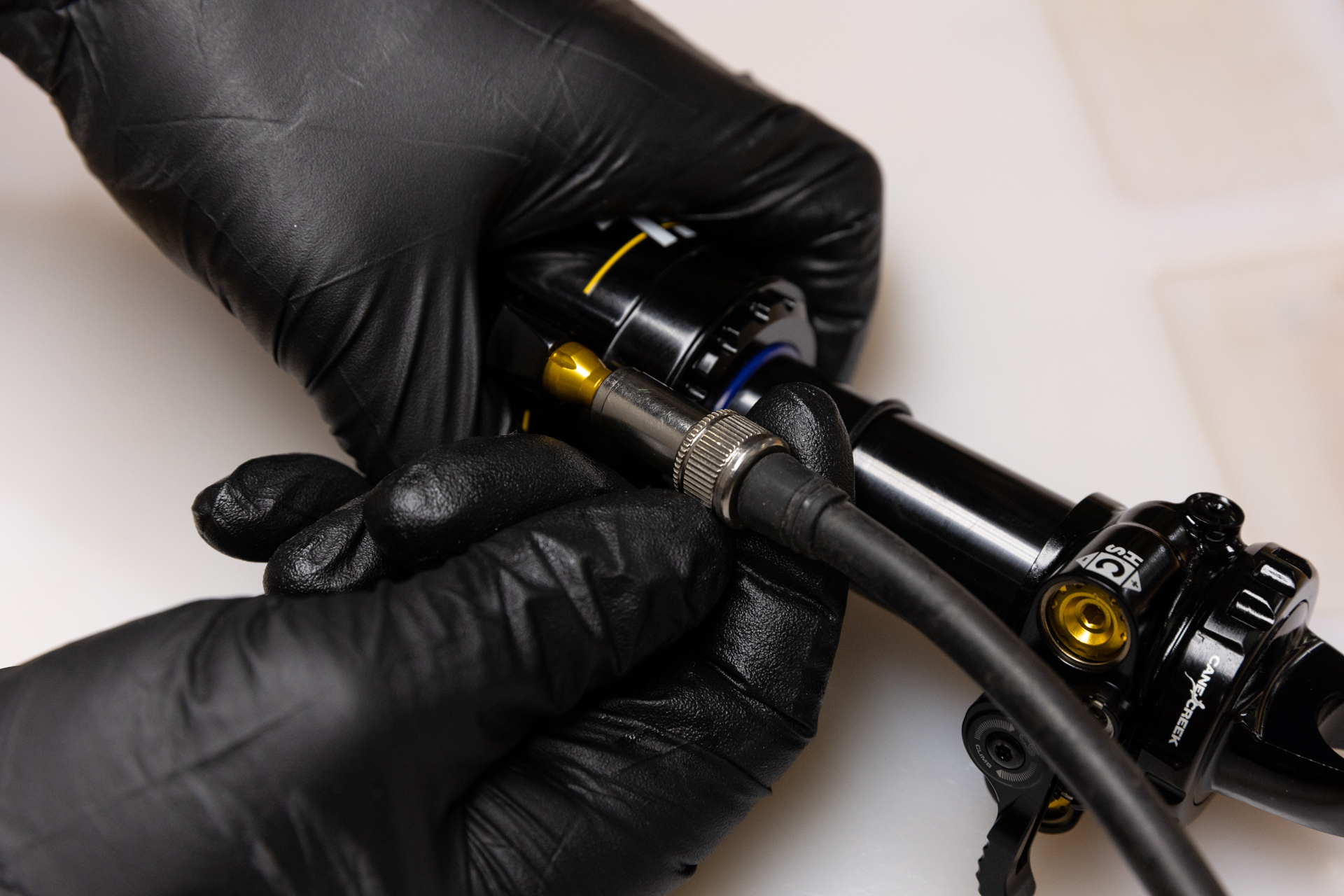
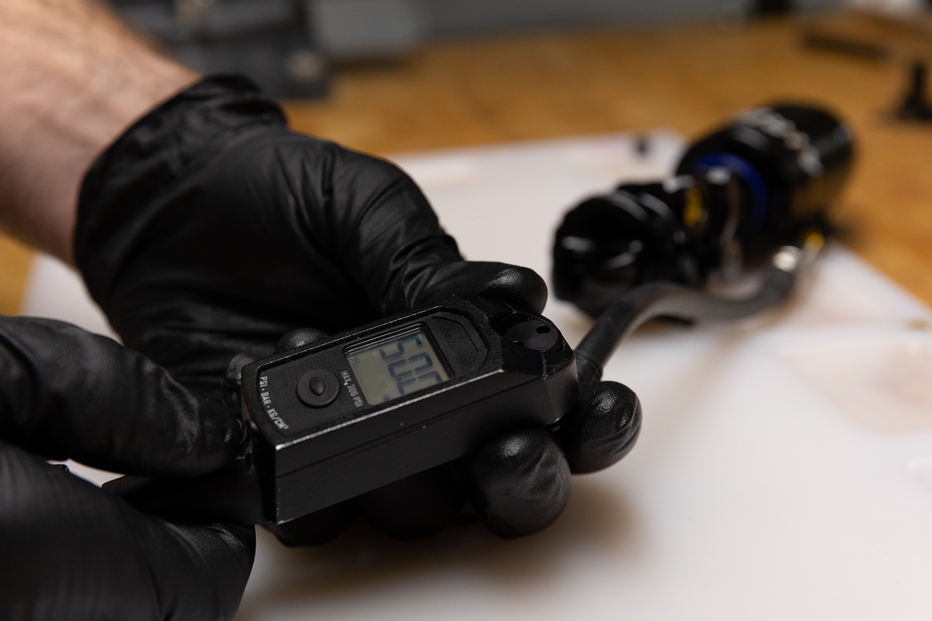
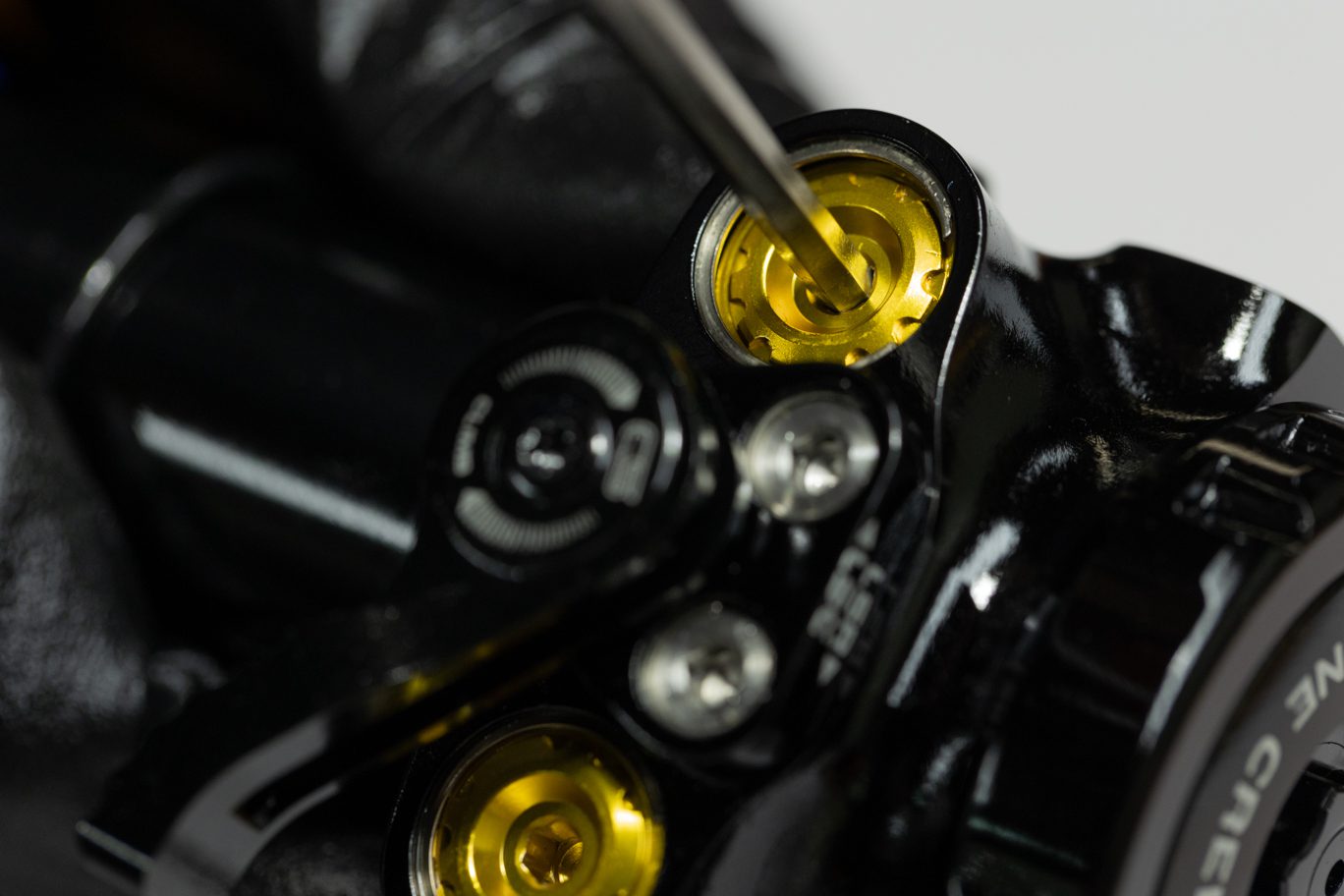
Set adjusters to factory neutral: HSC & HSR 2.5 turns from full bottom (or 2 turns from full open); LSC 11 clicks from full bottom; LSR 13 from full bottom. Using hand dyno, test shock for function. Ensure Climb Switch engages and operates properly. Turn individual adjusters to test each one. Set back to original tune if desired.
Install any bushings and hardware.

Monday: 10:00 am – 5:00 pm
Tuesday – Thursday: 10:00 am – 5:00 pm
Friday: 10:00 am – 5:00 pm
Saturday – Sunday: Closed